Constant intensity acoustic propagation in the presence of non-uniform properties and impedance discontinuities: Hermitian and non-Hermitian solutions
Abstract
Propagation of sound through a non-uniform medium without scattering is possible, in principle, if the density and acoustic compressibility assume complex values, requiring passive and active mechanisms, also known as Hermitian and non-Hermitian solutions, respectively. Two types of constant intensity wave conditions are identified: in the first the propagating acoustic pressure has constant amplitude, while in the second the energy flux remains constant. The fundamental problem of transmission across an impedance discontinuity without reflection or energy loss is solved using a combination of monopole and dipole resonators in parallel. The solution depends on an arbitrary phase angle which can be chosen to give a unique acoustic metamaterial with both resonators undamped and passive, requiring purely Hermitian acoustic elements. For other phase angles one of the two elements must be active and the other passive, resulting in a gain/loss non-Hermitian system. These results prove that uni-directional and reciprocal transmission through a slab separating two half spaces is possible using passive Hermitian acoustic elements without the need to resort to active gain/loss energetic mechanisms.
I Introduction
Sound in non-uniform materials is dominated by multiple scattering with the result that energy cannot propagate coherently in a given direction without loss. As a simple example, an acoustic impedance discontinuity in a one dimensional (1D) acoustic system causes reflection and resultant loss of energy in the transmitted wave. Even a single impedance discontinuity can drastically reduce the transmitted energy, as for instance, at an air-water interface. This effect is reciprocal in that the same fraction of energy is lost regardless of the incidence direction. Scattering and loss of forward propagating energy are inevitable in a classical or passive, disordered wave medium, now often referred to as a Hermitian system.
Allowing the acoustic medium to become non-Hermitian, in particular through the introduction of active materials which require external energy input, makes it possible to avoid scattering and achieve so-called constant intensity waves. This has been demonstrated theoretically and in simulations [1, 2, 3, 4]. The application of these ideas to acoustics was experimentally demonstrated in a 1D waveguide containing scatterers [5]. By adding discrete non-Hermitian elements comprising loudspeakers the backscatter was eliminated and perfect transmission obtained. Similar introduction of non-Hermitian elements in a multilayered 1D acoustic medium [6] has been shown computationally to achieve constant intensity wave propagation with no backscatter.
Non-Hermitian acoustics has been of interest at least since the concept of a system with balanced gain and loss, also known as a parity-time (PT) symmetric system, was proposed [7] in 2014. Applications include a metamaterial device formed by a pair of electro-acoustic resonators realizing an acoustic coherent perfect absorber [8], the emergence of exceptional points (EPs) in PT acoustics [9], and coherent acoustic propagation in turbulent fluid flow [10]. A recent review [11] provides an overview of these and other implications and applications of non-Hermitian acoustics. While certainly of interest, non-Hermitian acoustic systems require complicated energy intense active elements, and are to be avoided if purely passive solutions can achieve the same results.
Our objective is to examine the theory underlying constant intensity acoustic propagation with no backscatter in disordered systems. Two types of constant intensity acoustics in one dimension are identified: (i) propagation with constant magnitude of the acoustic pressure, and (ii) propagation with constant acoustic energy flux. Two similar but different equations relating the material proparties are obtained depending on which constant intensity definition is considered. We then focus on constant intensity propagation across a material discontinuity. We show that sub-wavelength actuators, either passive or active, can ensure perfect transmission with no reflection or energy loss at material discontinuities that otherwise generate reflection and reduce the transmitted energy. The point actuators are modeled as acoustic lumped elements, specifically monopole and dipole resonators, with an example given using Helmholtz and membrane resonators.
The outcome of the analysis is a proposal for a new type of metamaterial that provides total transmission with no loss in energy across an impedance discontinuity. The metamaterial, or meta-atom since it is a sub-wavelength lumped element, is a passive undamped combination of monopole and dipole resonators in parallel. This demonstrates that constant intensity acoustic propagation in a discretely disordered system does not require non-Hermitian elements but may be achieved with the use of standard lossless passive lumped elements acting in parallel.
The outline of the paper is as follows. Basic equations of constant intensity acoustics are derived in Section II, where the two definitions of constant intensity are distinguished. The acoustic elements necessary for constant intensity propagation across discontinuities are introduced in Section III. The main result of the paper is in Section IV where it is shown that a combination of passive undamped monopole and dipole resonators achieve perfect transmission across an impedance discontinuity with no scattering or energy loss. Discussion and conclusions are provided in Section V.
II Constant intensity equations
II.1 Basic equations
Time harmonic motion of frequency is considered with the time-dependent factor omitted. The acoustic momentum and constitutive equations are
| (1a) | ||||
| (1b) | ||||
where , , , and are the acoustic pressure, particle velocity, density, and compressibility (inverse of bulk modulus), respectively, all possibly functions of position . Eliminating yields an equation for the pressure only
| (2) |
The density and compressibility may be complex valued, corresponding to a passive system if and . The system is active, or non-Hermitian, if and/or , requiring an external source of energy to maintain the steady state. For the remainder of the paper we specialize to uni-dimensional acoustics , so that Eq. (2) is
| (3) |
where .
We consider and to be functions of position, which, as we will see in Section IV, is critical in dealing with impedance discontinuities. We also note that the fundamental paper in the field of constant intensity acoustics [5] assumes constant with variable density , but uses the incorrect equation (Eq. (4) of Rivet2018 [5]).
In order to obtain constant intensity uni-directional wave motion we start with the ansatz
| (4) |
for constant , where has dimensions of slowness. Equation (3) becomes
| (5) |
If both the density and compressibility are constant, Eq. (5) has the solution
| (6) |
as expected for uni-directional non-dispersive wave propagation. Otherwise is a function of , and .
According to Eqs. (1a) and (4) the particle velocity is
| (7) |
The ratio is therefore the local acoustic admittance , or equivalently, we can identify as the local impedance . The acoustic impedance is where is the local phase speed. Equation (5) can be rewritten as an equation for the impedance
| (8) |
which shows that in regions where constant that the impedance (equivalently the admittance ) is constant and given by .
II.2 Example: Total energy absorption
Assuming to be constant and real, Eq. (9) gives
| (10) |
This complex-valued compressibility is passive or active depending as or , respectively. The physical consequences can be seen through the energy flux averaged over a period,
| (11) |
Energy flux is constant if is also constant. A decreasing as a function of leads to a diminishing energy flux, consistent with the passive damping caused by . Conversely, increases with if , corresponding to an active non-Hermitian acoustic compressibility.
Consider the following example for with associated passive compressibility with damping
| (12) |
where . According to Eq. (11) the energy flux on either side of is directed towards with . The compressibility of Eq. (12), which is a symmetric function of , causes waves from either direction to be totally absorbed, with no backscatter. The material acts as an acoustic black hole.
II.3 Constant amplitude or constant energy?
The above example shows that even though the pressure amplitude remains constant the associated wave energy can decrease or increase. This suggests a more reasonable definition of "constant intensity" that the energy flux is constant even as the impedance changes. With that in mind the following ansatz is more appropriate than Eq. (4):
| (13) |
for constant , where from now on the impedance is defined . This solution provides the same energy flux in regions of different but constant . A Riccati equation analogous to Eq. (8) follows from Eq. (13)
| (14) |
where . We do not pursue this equation further. We will however provide an exact solution to Eq. (13) in the next Section for the important case of a point discontinuity in acoustic properties.
Our focus on a point discontinuity in impedance as compared with a continuous variation is because the latter requires a continuous variation in possibly active material properties. Any discontinuity in impedance leads to scattering (reflection) and loss of transmitted energy. We therefore consider what is necessary to maintain the forward propagating wave at constant intensity according to Eq. (13) in the presence of point changes in impedance. In order to address this we will take a step back to the fundamental equations (1) since Eq. (14) is based on smoothly varying impedance and is not suitable for point discontinuities. First, we introduce the elements to achieve one-way constant intensity propagation across the discontinuities.
III Monopole and dipole resonators
Monopole and dipole resonators have been the workhorses of acoustic metamaterials: Helmholtz resonators (monopoles) provide the basis for negative effective compressibility [12, 13, 14, 15, 16], while dipole membrane resonators yield negative effective inertia [17, 14, 18, 16]. Together they lead to the possibility of so-called doubly negative properties in acoustic metamaterials; in fact the earliest notions in metamaterials are generally agreed to revolve around concepts of negative properties, see for instance the historical review of Carlin1964 [19]. Monopole and dipole resonators in combination can provide total energy absorption [20], using a design that is closely related to the present one proposed in the next Section [21]. Despite the recent successful use of sub-wavelength acoustic lumped elements it should be borne in mind that they have a century long history in the development of analog acoustic control, particularly in acoustic wave filters [22, 23, 24].
Lumped parameter acoustic elements consisting of a Helmholtz resonator and a sprung mass or membrane are shown in Figure 1. In preparation for dealing with constant intensity across an interface we first consider each element situated between acoustic fluids with properties , on the left and , on the right. The membrane is placed so that it separates the fluids. As suggested in the Appendix, the Helmholtz resonator fluid can be taken as one of the two with the neck inserted in the respective fluid close to the interface. Alternatively, the monopole element could be provided by a Hybrid Membrane (HM) resonator [21] situated the same way as the HR in Figure 1, or by a pair of Decorated Membrane (DM) resonators [21] placed parallel to the membrane resonator separating the fluids as in Fig. 1(a) of [21].
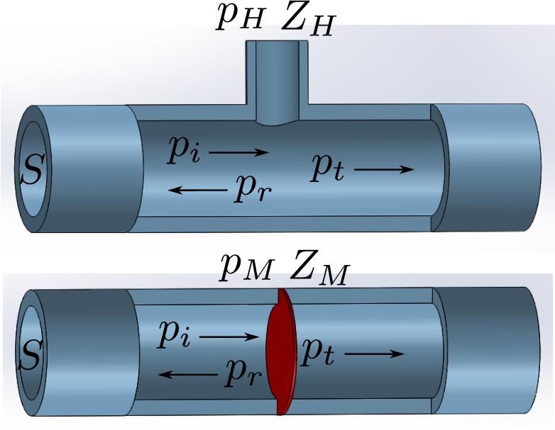
With as acoustic pressure, as volumetric velocity, the incident, reflected and transmitted quantities are related by the , , , where , with the acoustic impedance and the waveguide cross-sectional area, Figure 1. The Helmholtz and membrane resonators are defined by impedances and such that and , respectively. The systems are passive if , , they are otherwise active. Models for both types of acoustic elements are discussed in the Appendix.
The conditions for the attached Helmholtz resonator transmission-reflection problem are
| (15) | ||||
while those for the in-line mass-spring system are
| (16) | ||||
Solving for the reflection and transmission coefficients, defined by , , gives
| (17a) | ||||
| (17b) | ||||
If a transmission coefficient of unity can be achieved with the Helmholtz resonator by choosing , yielding and . This passive but dissipative element achieves one way propagation but at the expense of energy loss since a transmission coefficient of magnitude is necessary to maintain the same energy flux in as for the incident wave in (see next section for details).
Similarly, one way propagation across the discontinuity with is achieved with the passive membrane of impedance , which gives and . Again, this is less than the required transmission amplitude for maintaining the wave energy, with the energy loss associated with the damping effect of the membrane.
IV Propagation across impedance discontinuities
Here we show that constant intensity propagation through an impedance discontinuity can be achieved with two passive undamped elements at the point of discontinuity, or by a combination of one active element with a damped passive element.
IV.0.1 Monopole and dipole strengths
We consider an acoustic waveguide with an impedance discontinuity at , i.e. . This could be due to different fluids in a waveguide of constant cross-section, or a change in cross-sectional area with the same fluid on either side. In the neighborhood of we therefore have where and is the Heaviside step function. We consider the ansatz
| (18a) | ||||
| (18b) | ||||
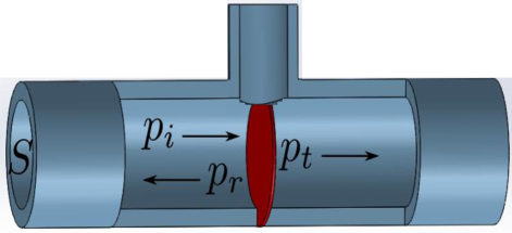
where , , is the delta function, and and are constants. The concentrated density and compressibility of Eq. (18) correspond to a combination of dipole and monopole resonators in parallel, as exemplified in Fig. 2. A similar parallel combination of monopole and dipole resonators was used [21] to achieve a quite different effect: total absorption. Apart from the different application, we are here considering the pair of elements positioned right at the discontinuity of impedance, whereas Yang et al. [21] had no discontinuity.
Equations (1a) and (1b) now become
| (19a) | ||||
| (19b) | ||||
Both and are smooth functions of near the interface but they can be discontinuous at . To be specific, we assume they have distinct values on either side of the interface: and . Equations (19) imply jump conditions connecting the values of and across the interface. The functions multiplying the Dirac delta functions in Eqs. (19) are themselves discontinuous precisely at , and therefore some care needs to be taken in deriving the jump conditions in the usual manner by integration. We use the identity , which can be seen by noting that the delta function is symmetric in and can be written in various forms as a limit. For instance, taking and integrating from to gives the identity. Note that this identity is not universally applicable but depends upon the context, with some embarrassing results when used where it should not be [25]. In summary, Eqs. (19) give
| (20a) | ||||
| (20b) | ||||
where and provide the required monopole and dipole strengths.
The connection between the point scatterers of Eq. (18) and the membrane and Helmholtz resonators can be found by first considering reflection and transmission from the monopole scatterer, i.e. Eq. (18) with . In this case is continuous at , and a simple analysis gives
| (21) |
Conversely, reflection and transmission from the dipole scatterer, i.e. Eq. (18) with has continuous at with
| (22) |
Setting requires that the impedances are related by
| (25) |
and the resulting transmission coefficient is
| (26) |
Our objective is to find a metamaterial that achieves a designated transmitted wave amplitude. With that in mind we rewrite the previous equations to express and in terms of and the impedances on either side of the interface:
| (27a) | ||||
| (27b) | ||||
IV.0.2 Explicit expressions for the monopole and dipole impedances
The incident energy flux, averaged over a cycle, is for , which is . The corresponding transmitted energy flux is . Assuming real-valued impedances , this means that in order to maintain the energy flux, or wave energy, we need
| (28) |
for arbitrary phase angle . Equations (27) become
| (29a) | ||||
| (29b) | ||||
or after some simplification,
| (30a) | ||||
| (30b) | ||||
where
| (31) |
The explicit expressions of Eq. (30), or the relations
| (32) |
indicate that if one of the resonators is passive and lossy, e.g. Re, then the other is active with gain, Re. Since the transmitted acoustic pressure has the same energy as that of the incident wave and because there is no reflection, the gain and loss of the two elements must cancel each other in order to conserve wave energy.
Both elements are passive if , in which case, taking , we have a unique pair of undamped passive solutions
| (33) |
The elements are lossless by virtue of the fact that both have zero real part. Furthermore, if one is mass-like the other acts as a stiffness .
IV.0.3 Example: transmission through an air-water interface
As an example we consider a water-air interface, a common acoustic boundary but with a rather extreme impedance mismatch of approximately 3,644 to 1. We assume that the interface is equipped with membrane and Helmholtz resonators in parallel with impedances given by Eqs. (36) and (40)1. In order to satisfy the inequality , from Eq. (32), the target frequency for full transmission, must lie between the smaller and larger of . To be specific, we assume and therefore . Furthermore, for the sake of simplicity we assume that , and so . Equation (33) with and Eqs. (36) and (40)1 then imply
| (34) |
The material impedances are defined by the water-air interface, with and for water and air as kg/m3, m/s and kg/m3, m/s, respectively. We then select the following parameters: the HR bulb and neck fluids and hence the values of and , the waveguide cross-sectional area , the membrane and Helmholtz resonance frequencies , and the frequency for total transmission . Equation (IV.0.3) then implies values for the membrane mass and Helmholtz resonator volume , and Eq. (40)2 then yields the ratio for the HR neck (see the Appendix).
For the example considered, the HR bulb and neck fluids are both air, the full-transmission frequency is Hz, the resonators frequencies are Hz, Hz, and the waveguide cross-section is circular of radius m. We then find from Eq. (IV.0.3) that kg and cm3, and from Eq. (40)2 that m. The latter corresponds, for instance, to a cylindrical HR neck of radius cm and length cm. These parameters ensure perfect transmission at the chosen operating frequency, in this case Hz.
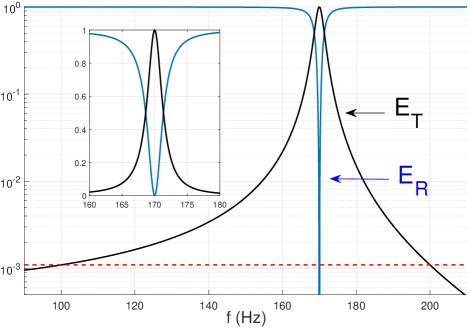
Figure 3 shows the fractional reflected and transmitted energy fluxes as a function of frequency for these parameters, where
| (35) |
with . The inset in Fig. 3 indicates perfact transmission at the selected frequency Hz. Significant transmission occurs in a narrow bandwidth of about 4 Hz. However, is greater than the ambient value of an air-water interface for every frequency over the broad bandwidth between the two resonance frequencies and . Figure 3 shows that the transmitted energy equals the ambient value at both and , and it lies below the ambient value for frequencies less than and greater than . The pair of passive resonators therefore act as a broadband transmission amplification device that achieves full transmission over a narrow range of frequencies centered at .
V Discussion and conclusions
The main result of this paper is that zero-scatter one-way propagation in the presence of an impedance discontinuity can be achieved by purely passive methods. There is no need to resort to more complicated active systems using gain/loss mechanisms characteristic of non-Hermitian acoustics.
Two ways of looking at constant intensity acoustics for one dimensional wave motion have been considered: constant pressure amplitude or constant energy flux. Of the two, the constraint of constant energy is more sensible. This is evident in the solution for transmission across a material discontinuity. A change in impedance causes scattering, but introduction of the combined monopole+dipole acoustic "meta-atom" of Eq. (29) results in total transmission with no loss in energy. This solution contains an arbitrary phase which "rotates" the solution in the space of passive/active metamaterials. When the metamaterial becomes passive and undamped. Otherwise, the two elements form a gain/loss pair with one active and the other passive and damped that together ensure that the transmitted wave has the same energy as the incident one.
Transmission through the monopole+dipole system (29) or (33) is reciprocal in that it provides transmission with full energy conservation and zero reflection for incidence from either side of the impedance discontinuity. This means, for instance, that perfect transmission through a finite slab or layer of material can be achieved by placing the same monopole+dipole system at each end.
In conclusion, the paper provides fundamental results relevant to sound wave amplification and scattering cancellation. The proposed acoustic metamaterial comprising a pair of tuned resonators, passive/passive or active/passive, could enable a huge increase in acoustic communication efficiency across disparate interfaces, as shown in the example for passive transmission amplification between air and water.
Acknowledgements.
This work was supported by NSF EFRI award no. 1641078.*
Appendix A Impedance models
A.1 Membrane or dipole impedance
The impedance for a lossless membrane resonator follows from e.g. Lee2009 [17, 16] as
| (36) |
This can be envisaged as a membrane separating the fluid on either side, and subject to a pressure differential across it. The mass is the total mass, and the stiffness arises from the elasticity as it is stretched under pressure.
A more precise model, due to Ingard1954 [26] and based on Morse1948 [27, p. 201], considers the dynamics of a membrane of wavenumber , radius , yielding
| (37) |
The resonant frequency of the membrane, , can be calculated analytically by considering free flexural vibration of circular plate clamped all around the circumference. The general solution in polar coordinates is [28] , where ; and are the Bessel functions of the first kind and the modified Bessel functions of the first kind, respectively. Clamped boundary conditions at lead to the eigenvalue problem . The natural frequencies of the circular membrane plate can be calculated from the roots . Here we are only interested in the fundamental mode, i.e. mode. Taking the number of nodal diameter as and only solving for the first mode, we have . Among related models for the acoustic impedance of internal mass-spring resonators [29, 30] and membrane oscillators we note the explicit expression of BongardLissekMosig2010 [31]:
| (38) |
A.2 Helmholtz resonator or monopole impedance
The Helmholtz resonator (HR) impedance is a classic result [32, 33] usually considered in the context of a uniform ambient acoustic medium. The HR comprises a volume of fluid - the bulb- which acts as a mechanical spring, and a volume of fluid - the neck - acting as a mass. The present application envisages the Helmholtz resonator located at an impedance discontinuity, Fig. 2. The placement of the neck can therefore be in either of the fluids, but is perhaps simpler if the fluid in the neck is the same as that into which the neck enters. In the example considered in §IV the fluid is air. The classical HR is normally considered to contain a single acoustic fluid but here we consider the possibility of different fluids in the bulb and neck. In order to avoid mixing of the two acoustic fluids it would be necessary to introduce an impermeable membrane with ignorable acoustic influence. That means a material both light and compliant enough that it does not cause pressure or velocity jumps, while separating the acoustic fluids. The reason we consider the possibility of two fluids is to increase the potential range of the HR parameters, which for the purposes considered here can be very demanding. At the same time, the fluids should be such that the potential and kinetic energies over one cycle are predominantly located in the bulb and neck fluids, respectively.
With these considerations in mind, generalizing §10 of KinslerFrey [34] to the two distinct fluids in the bulb and neck, we model the undamped HR as
| (39) |
where is the volume of the bulb acoustic fluid with compressibility , and , , are the neck fluid density, cross-sectional area and length, respectively. The impedance is therefore
| (40) |
where the resonance frequency depends upon the bulb compressibility and the neck fluid density , along with the geometric parameters , and .
References
- [1] K. G. Makris, Z. H. Musslimani, D. N. Christodoulides, and S. Rotter, “Constant-intensity waves and their modulation instability in non-Hermitian potentials,” Nature Communications 6(1) (2015) \dodoi10.1038/ncomms8257.
- [2] K. G. Makris, A. Brandstötter, P. Ambichl, Z. H. Musslimani, and S. Rotter, “Wave propagation through disordered media without backscattering and intensity variations,” Light: Science & Applications 6(9), e17035–e17035 (2017) \dodoi10.1038/lsa.2017.35.
- [3] A. Brandstötter, K. G. Makris, and S. Rotter, “Scattering-free pulse propagation through invisible non-Hermitian media,” Physical Review B 99(11), 115402 (2019) \dodoi10.1103/physrevb.99.115402.
- [4] I. Komis, S. Sardelis, Z. H. Musslimani, and K. G. Makris, “Equal-intensity waves in non-Hermitian media,” Physical Review E 102(3), 032203 (2020) \dodoi10.1103/physreve.102.032203.
- [5] E. Rivet, A. Brandstötter, K. G. Makris, H. Lissek, S. Rotter, and R. Fleury, “Constant-pressure sound waves in non-Hermitian disordered media,” Nature Physics 14(9), 942–947 (2018) \dodoi10.1038/s41567-018-0188-7.
- [6] S. An, T. Liu, S. Liang, H. Gao, Z. Gu, and J. Zhu, “Unidirectional invisibility of an acoustic multilayered medium with parity-time-symmetric impedance modulation,” Journal of Applied Physics 129(17), 175106 (2021) \dodoi10.1063/5.0039432.
- [7] X. Zhu, H. Ramezani, C. Shi, J. Zhu, and X. Zhang, “PT-symmetric acoustics,” Physical Review X 4(3) (2014) \dodoi10.1103/physrevx.4.031042.
- [8] R. Fleury, D. Sounas, and A. Alù, “An invisible acoustic sensor based on parity-time symmetry,” Nature Communications 6(1) (2015) \dodoi10.1038/ncomms6905.
- [9] C. Shi, M. Dubois, Y. Chen, L. Cheng, H. Ramezani, Y. Wang, and X. Zhang, “Accessing the exceptional points of parity-time symmetric acoustics,” Nature Communications 7(1) (2016) \dodoi10.1038/ncomms11110.
- [10] Y. Aurégan and V. Pagneux, “Symmetric scattering in flow duct acoustics,” Physical Review Letters 118(17), 174301 (2017) \dodoi10.1103/physrevlett.118.174301.
- [11] Z. Gu, H. Gao, P.-C. Cao, T. Liu, X.-F. Zhu, and J. Zhu, “Controlling sound in non-Hermitian acoustic systems,” Physical Review Applied 16(5), 057001 (2021) \dodoi10.1103/physrevapplied.16.057001.
- [12] N. Fang, D. Xi, J. Xu, M. Ambati, W. Srituravanich, C. Sun, and X. Zhang, “Ultrasonic metamaterials with negative modulus.,” Nature Mat. 5(6), 452–456 (2006) \dodoi10.1038/nmat1644.
- [13] S. H. Lee, C. M. Park, Y. M. Seo, Z. G. Wang, and C. K. Kim, “Acoustic metamaterial with negative modulus,” Journal of Physics: Condensed Matter 21(17), 175704 (2009) http://dx.doi.org/10.1088/0953-8984/21/17/175704 \dodoi10.1088/0953-8984/21/17/175704.
- [14] S. H. Lee, C. M. Park, Y. M. Seo, Z. G. Wang, and C. K. Kim, “Composite acoustic medium with simultaneously negative density and modulus,” Phys. Rev. Lett. 104(5) (2010) http://dx.doi.org/10.1103/physrevlett.104.054301 \dodoi10.1103/physrevlett.104.054301.
- [15] Y. Lai, Y. Wu, P. Sheng, and Z.-Q. Zhang, “Hybrid elastic solids,” Nature Materials 10(8), 620–624 (2011) http://dx.doi.org/10.1038/NMAT3043 \dodoi10.1038/nmat3043.
- [16] S. H. Lee and O. B. Wright, “Origin of negative density and modulus in acoustic metamaterials,” Physical Review B 93(2), 024302 (2016) http://dx.doi.org/10.1103/PhysRevB.93.024302 \dodoi10.1103/physrevb.93.024302.
- [17] S. H. Lee, C. M. Park, Y. M. Seo, Z. G. Wang, and C. K. Kim, “Acoustic metamaterial with negative density,” Physics Letters A 373(48), 4464–4469 (2009) http://dx.doi.org/10.1016/j.physleta.2009.10.013 \dodoi10.1016/j.physleta.2009.10.013.
- [18] Y. M. Seo, J. J. Park, S. H. Lee, C. M. Park, C. K. Kim, and S. H. Lee, “Acoustic metamaterial exhibiting four different sign combinations of density and modulus,” J. Appl. Phys. 111(2), 023504 (2012) http://dx.doi.org/10.1063/1.3676262 \dodoi10.1063/1.3676262.
- [19] H. Carlin, “Guest editorial-unconventional network theory,” IEEE Trans. Circuit Theory 11(3), 324–326 (1964) http://dx.doi.org/10.1109/tct.1964.1082314 \dodoi10.1109/tct.1964.1082314.
- [20] M. Yang and P. Sheng, “Sound absorption structures: From porous media to acoustic metamaterials,” Annual Review of Materials Research 47(1), 83–114 (2017) \dodoi10.1146/annurev-matsci-070616-124032.
- [21] M. Yang, C. Meng, C. Fu, Y. Li, Z. Yang, and P. Sheng, “Subwavelength total acoustic absorption with degenerate resonators,” Applied Physics Letters 107(10), 104104 (2015) \dodoi10.1063/1.4930944.
- [22] G. W. Stewart, “Acoustic wave filters,” Phys. Rev. 20, 528–551 (1922) http://link.aps.org/doi/10.1103/PhysRev.20.528 \dodoi10.1103/PhysRev.20.528.
- [23] W. P. Mason, “The propagation characteristics of sound tubes and acoustic filters,” Phys. Rev. 31(2), 283–295 (1928) http://dx.doi.org/10.1103/PhysRev.31.283 \dodoi10.1103/physrev.31.283.
- [24] R. B. Lindsay, “Note on the theory of acoustic wave filters,” Phys. Rev. 34(4), 652–655 (1929) http://dx.doi.org/10.1103/PhysRev.34.652 \dodoi10.1103/physrev.34.652.
- [25] D. Griffiths and S. Walborn, “Dirac deltas and discontinuous functions,” American Journal of Physics 67(5), 446–447 (1999) \dodoi10.1119/1.19283.
- [26] U. Ingard, “Transmission of sound through a stretched membrane,” The Journal of the Acoustical Society of America 26(1), 99–101 (1954) \dodoi10.1121/1.1907298.
- [27] P. M. Morse, Vibration and Sound, second ed. (McGraw-Hill, New York, 1948).
- [28] A. Leissa, Vibration of Plates (ASA, Woodbury, NY, 1993).
- [29] Z. Liu, Z. Zhang, Y. Mao, Y. Y. Zhu, Z. Yang, C. T. Chan, and P. Sheng, “Locally resonant sonic materials,” Science 289(5485), 1734–1736 (2000) \dodoi10.1126/science.289.5485.1734.
- [30] B. Mace, “Discussion: "Dynamics of Phononic Materials and Structures: Historical Origins, Recent Progress and Future Outlook," (Hussein, M.I., Leamy, M.J. and Ruzzene, M.),” Appl. Mech. Rev. 66, 045502+ (2014) \dodoi10.1115/1.4027723.
- [31] F. Bongard, H. Lissek, and J. R. Mosig, “Acoustic transmission line metamaterial with negative/zero/positive refractive index,” Phys. Rev. B 82(9) (2010) http://dx.doi.org/10.1103/PhysRevB.82.094306 \dodoi10.1103/physrevb.82.094306.
- [32] G. Stewart, “Acoustic wave filters; an extension of the theory,” Physical Review 25(1), 90 (1925).
- [33] G. Stewart, “Acoustic transmission with a Helmholtz resonator or an orifice as a branch line,” Physical Review 27(4), 487 (1926).
- [34] L. E. Kinsler, A. R. Frey, A. B. Coppens, and J. V. Sanders, Fundamentals of Acoustics, fourth ed. (Wiley, 2000), http://www.worldcat.org/isbn/0471847895.