Comparative study of H accumulation in differently oriented grains of Cu
Abstract
When metal surfaces are exposed to hydrogen ion irradiation, the light ions are expected to penetrate deep into the material and dissolve in the matrix. However, these atoms are seen to cause significant modification of surfaces, indicating that they accumulate in vicinity of the surface. The process known as blistering may reduces the vacuum dielectric strength above the metal surface, which shows a dense population of surface blisters.
In this paper, we investigate how a bubble can grow under the pressure exerted by hydrogen atoms on the walls of the bubble and how this affect to the surface of Cu, whether an external electric field is applied or not.
keywords:
Copper; Surface; Blisters; Hydrogen; Molecular dynamics;1 Introduction
The mechanisms behind the blistering process has been deeply studied in many materials due to its importance in the proper functioning of the devices which surfaces are exposed to hydrogen and noble gases [Hblisteringreview]. These light species accumulate in the lattice defects as well as in surfaces and grain boundaries [Bai10, Smi15, Yan15]. It has been shown that for hydrogen, the vacancies created in the bulk can accommodate more than one implanted ion [Ste11, ganchenkova2014, Korzhavyi2014] when the surfaces are irradiated with it. The hydrogen that is accumulated leads to an increase of the size of the empty regions and more ions can occupy this space [Hen05b], forming bubbles approximately 1.5 nm [thomson2015] to larger sizes. These defects are eventually observed in the exposed to irradiation surface, and are known as ”blisters” [Wan01, All20, Joh82, nakahara1989, taskaev2018].
Blistering is observed in tungsten, which is the most promising plasma-facing material for the future nuclear fusion power plants due to its high melting point, good thermal conductivity, low thermal expansion, significant strength at elevated temperatures and also its high sputtering threshold energy [barabash1999, nygren2011, alvarez2011, kaufmann2007]. However, it is still susceptible to suffer from it [Wan01, causey2001, Hen05b, thomson2015]. Blistering has been also observed in a number of materials such as V [pesch1980], Nb [schober1993], carbon steel [ju1985, iino1978, ravi1990], Fe [lee1987, lee1985, lee1989], Al[kamada1988, kamada1989, milacek1968a, milacek1968b, daniels1971, xie2015, sznajder2018] and Cu [Joh82, nakahara1989, nakahara1991, taskaev2018, fukui1995, robinson2017].
Moreover, the disruption of operation in accelerating devices such as the future Compact Linear Collider (CLIC) [CLIC] due to breakdowns [barengolts2018, kyritsakis2018], damaging the surface, is a bottleneck in the functioning of these systems. Norlund et al. suggested [Nord2012] and others further developed [Engelberg2018] that there is a correlation of the dependence of the breakdown rate (number of breakdowns per pulse) on the accelerating field gradient in radio-frequency (RFQ) accelerating Cu structures. A similar correlation was established in the direct-current (DC) experiments with different materials [descoeudres2009, Des10], where the materials appeared to rank according to their crystallographic lattice structure. Despite many materials showed much higher minimal breakdown field, Cu was select as the functional material for the CLIC [clicreport2018] due to its abundance, good conductivity and mechanical properties [descoeudres2009].
Previously, it was shown that the accumulation of implanted ions follows to pressurize gas as a consequence of rising density, then it leads to plastic deformation via bubble growth emitting dislocations. The emission of dislocations is due to exerted pressure by the gas to bubble walls [Lop21]. It is also known that continuous plastic deformation in metals changes their properties inducing hardening, hindering dislocation activity. On the other hand, blistering is seen to grow continuously with the increase of the ion beam fluence [nakahara1989, nakahara1991, taskaev2018]. However, we know that this is eventually noticed in the surface, and the dependence on the crystallographic orientation arises. However, the role of the grains and their orientation were not discussed. The grain orientation and its position from the surface, are determinant to understand the response of it under shear stress [SUN2021116474], according to Sun et al. They found that for \hkl[100]-oriented grains, at a given strain, the dislocation system behaves similarly in the surface or bulk, however for the \hkl[110] and \hkl[111] within a certain range, do behave differently whether is a bulk or surface grain. In Ref. [hansen2011], they deeply studied the relationship between the orientation, size and type of strain under the grain is to determine its response.
Computational studies on the effect of the stress on copper has been developed in different contexts. In Cu, Molecular dynamics (MD) has been used to study mechanical properties[heino1998] for the different crystallographic orientations; also the effect of several sizes and shapes of voids under tensile stress [wang2018, Lin2012] and triaxial stress [YANG2016917, seppala2004, seppala2005] considering the void coalescence. However, the combined effect of bubbles (H in this case) and different surface orientations has not been studied using MD.
In a previous work [Lop21], it was proved the emission of prismatic loops under hydrostratic stress from a pressurized bubble, showing that a number of shear loops surrounding the bubble can eventually form a prismatic loop, which is emitted not necessarily smaller than the void cross-section. Following these findings, we propose a new setup of simulations for reveal the mechanisms behind the surface modification under different surface orientations over a H bubble, considering the interaction of dislocations with the close Cu surface.
2 Methods
2.1 Computational simulations
PARCAS MD code [nor95] was used to perform the simulations. Mishin et al. developed the embedded atom model (EAM) interatomic potential [Mis01b] (Mishin potential), which was used to described the Cu-Cu interactions. Besides, following the previous work [Lop21], we include the description EAM formalism [foiles1987, baskes1987, angelo1995] for the H-H interactions and purely repulsive ZBL potential [ZBL] for Cu-H. Doing this, we can assure that all the pressure is exerted to the walls of the void.
We performed simulations using periodic boundary conditions in the x-y direction and open surface in the z direction. The simulations were carried out at 600 K using the Berendsen thermostat [ber84] (NVT) to scale the velocities of the atoms. At the bottom of the cell, a fixed layer was applied in order to prevent cell movement. The simulation time was 100 ps.
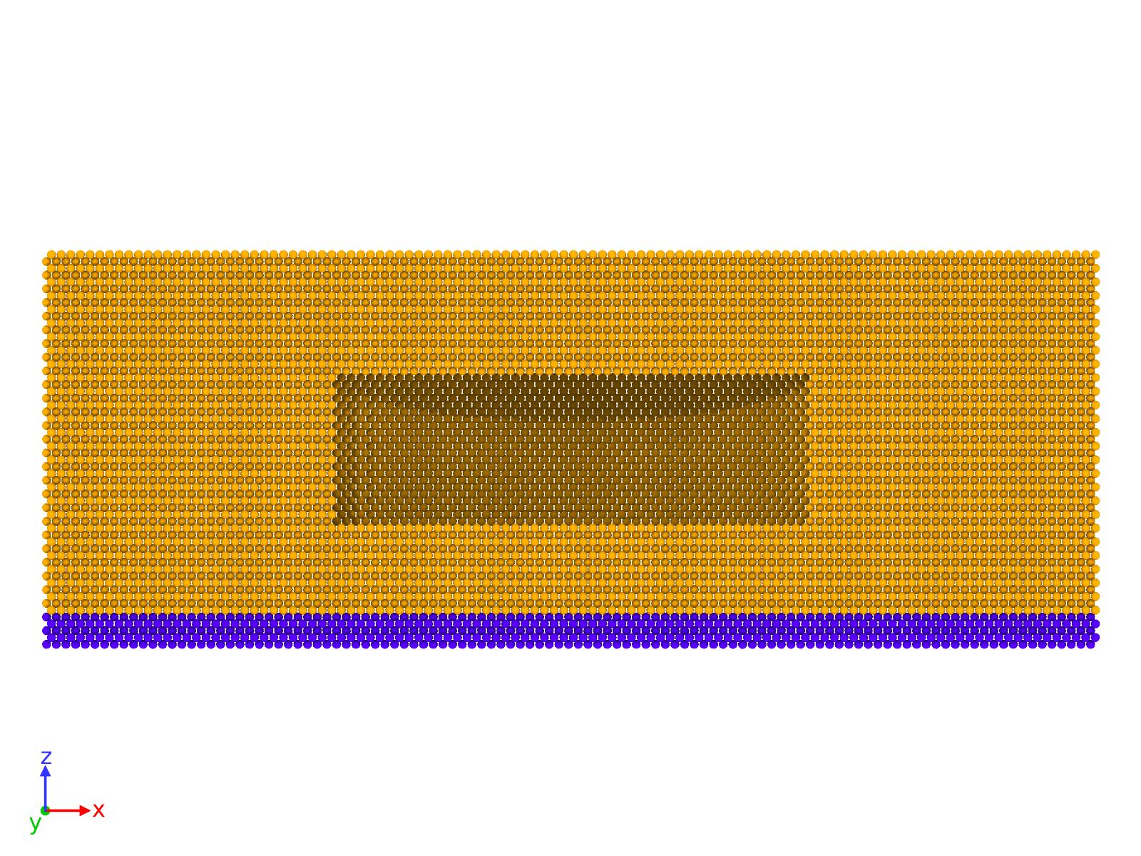
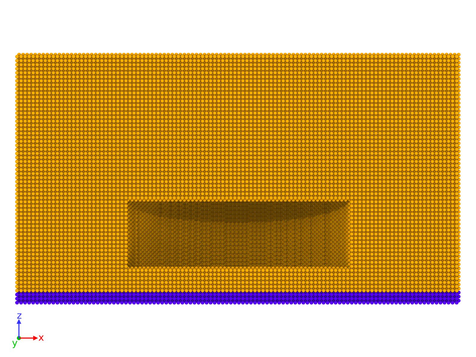
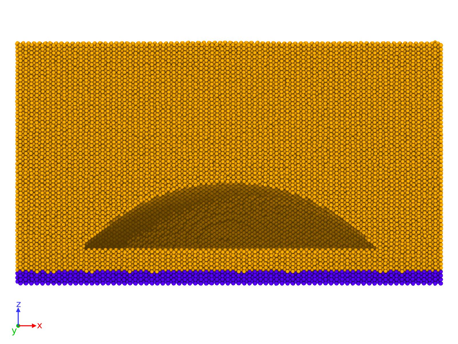
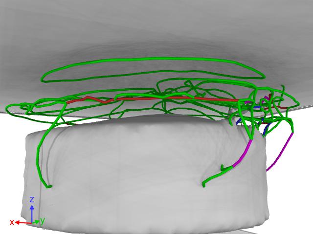
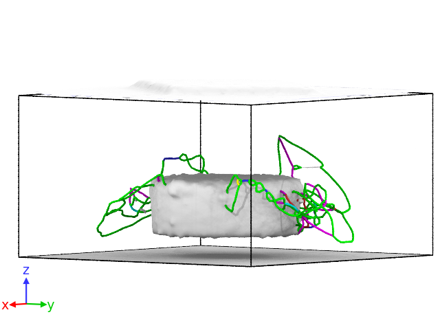
Our study is based in two types of voids: a disk-shaped void and a hemisphere-like void (see Figure 1). These shapes were selected in order to mimic the different shapes that are observed experimentally. These voids were inserted in differently oriented cells. In the case of the disk-shaped voids, we additionally simulated using voids closer to the surface at lower pressures. These cells were created using different orientations in the z-direction, i.e. the open surfaces, corresponding to \hkl(1 1 0), \hkl(1 0 0), and \hkl(1 1 1). With this, we analysed the effect of the hydrostatic pressure in the different surfaces. The volume of all the voids introduced is the same, only changing their shapes. In Table 1 the dimensions and number of atoms in cells are presented.
| Smaller cell disk-void \hkl(110) | Smaller cell disk-void \hkl(100) | Smaller cell disk-void \hkl(111) | |
|---|---|---|---|
| Cell dimensions (Å) | |||
| Number of Cu atoms | 648956 | 646924 | 664755 |
| Disk-void \hkl(110) | Disk-void \hkl(100) | Disk-void \hkl(111) | |
| Cell dimensions (Å) | |||
| Number of Cu atoms | 1036156 | 1014067 | 1048588 |
| Hemisphere-void \hkl(110) | Hemisphere-void \hkl(100) | Hemisphere-void \hkl(111) | |
| Cell dimensions (Å) | |||
| Number of Cu atoms | 1033830 | 1017695 | 1051281 |
We have tested different pressures (densities, nH/Vac(meaning number of H atoms per missing Cu atoms)) inside all the voids, located under the surfaces. In the smaller cells cases, we simulated different H pressures, but it is only at 20 kbar (nH/Vac1.2) when we indeed observe some changes in the structure. Densities of nH/Vac=1.2 and 2 (20 and 30 kbar respectively [Lop21]) were introduced tried in the larger cells with the disk-shaped void, so we can compare the effect of the bubble when is located at different distances. In the hemisphere-shaped voids, we introduced only nH/Vac= 2, because the lower density did not induce any remarkable change in the disk-shaped ones.
The volume of the voids, regardless the shape, is similar in all the cases.
In previous works [Lop21], we estimated that the solubility of H in Cu at 600 K and 20 kbar [Fromm1984] is very reduced. Hence, assume that most of the H will end up accumulating in a void, it is a fair approximation for our purpose: the response of the material under this hydrostatic stress.
For visualization of the results, we use the Open Visualization Tool (OVITO) [ovito]. We analyzed the stacking faults in the cells by using the centrosymmetry (CS) parameter [centrosymmetryparam] and the dislocation extraction algorithm (DXA) available in OVITO[dxaanalysis].
MDRANGE code [Nor94b] is used to estimate the penetration depth of 45 keV H ions in Cu. 10 000 cases are simulated in order to collect statistics. Contrarily to some conventional binary collisions approximation methods [SRIMbook], the different crystallographic orientations can be considered in the calculation [JUSSILA2018113].
3 Results
3.1 Experiments
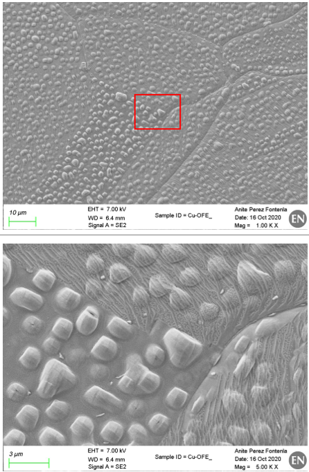
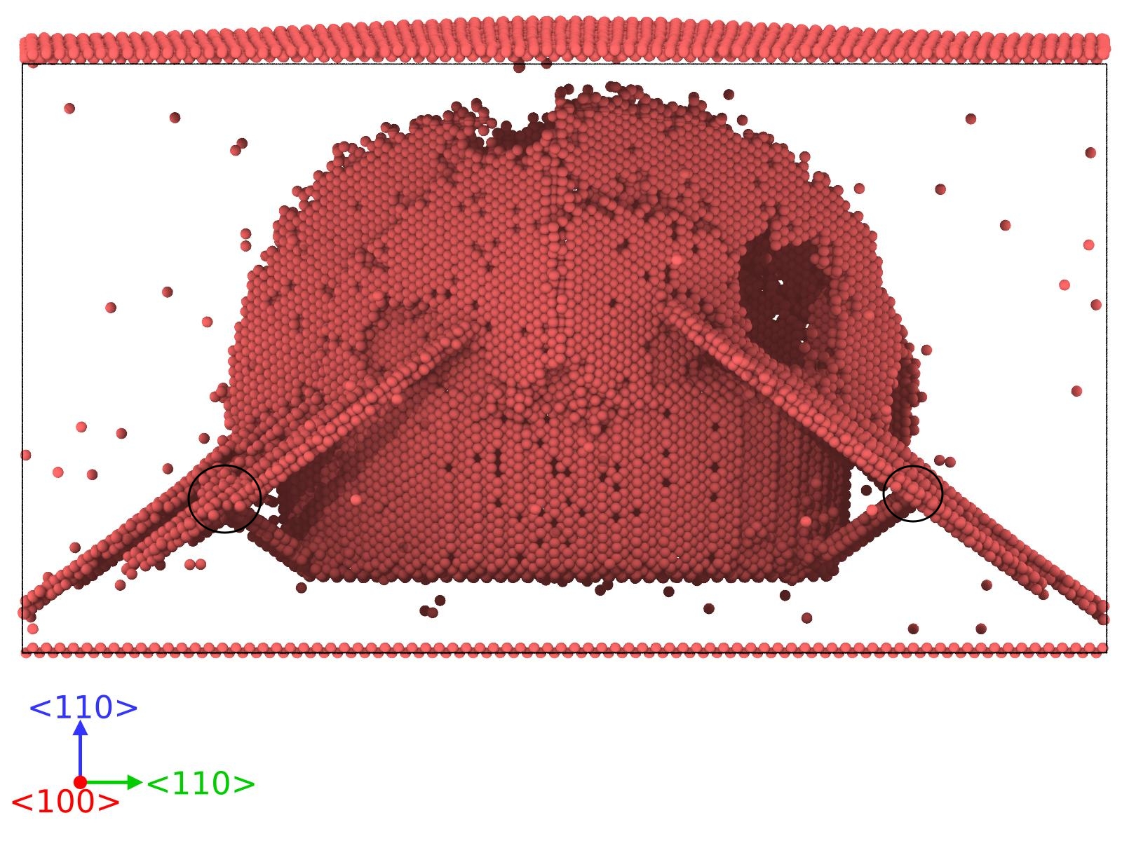
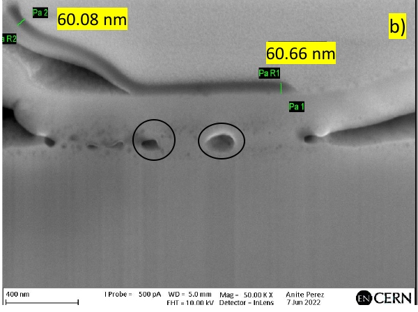
Figure 2 shows the Cu surface exposed to the H- ion irradiation for 40 hours reaching the fluence of cm-2. The image clearly shows formation of blisters with either rounded shape or having lids of random, but geometrically well defined shapes, in some cases showing signs of an opening at their apex, probably after having burst open. In some places, the blisters are self-organized in rows along specific crystallographic directions. These features indicate that the dislocation-mediated mechanism, whose linear nature, may explain the geometrically recognizable forms and alignment of the bubbles in a self-organized manner.
This observation motivated us to study the effect of hydrogen accumulation in voids, forming bubbles, following the effect that these bubbles may cause in the surface.
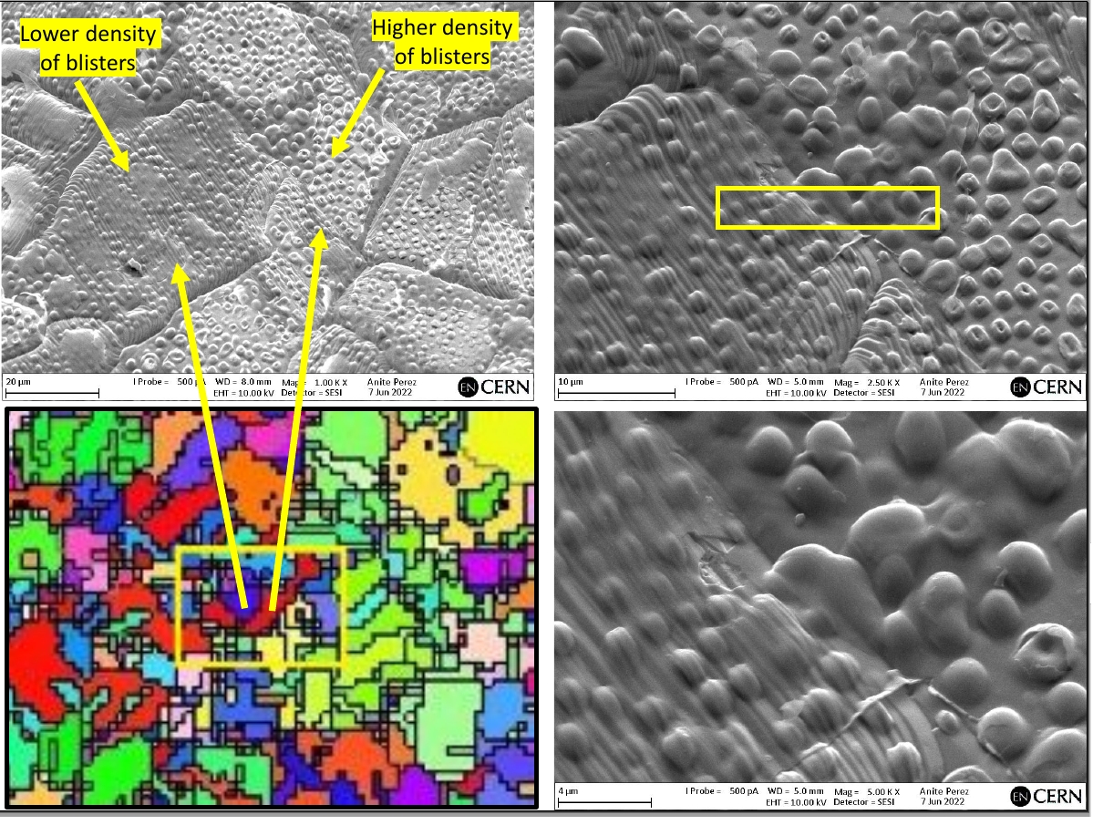
In Figure 3 we observe that the density of protrusions in the \hkl(100) grain is higher than in the \hkl(111), however the formation of them is observed in both.
3.2 Disk-shape bubble - Small cell
We simulated lower density (nH/Vac) in a disk-shaped bubble for a smaller cell differently oriented (see Figure 1 (a))
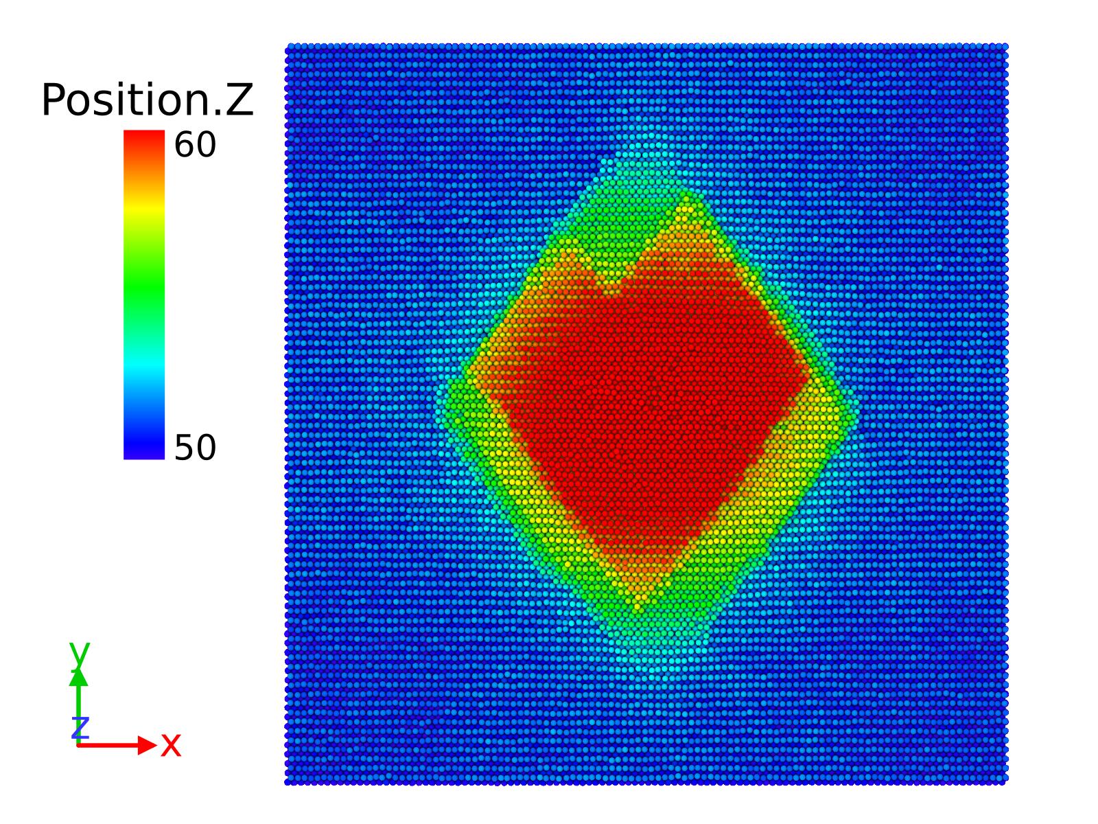
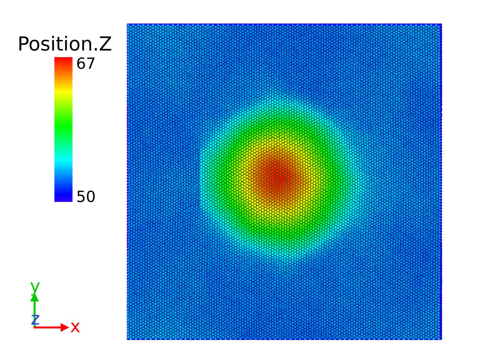
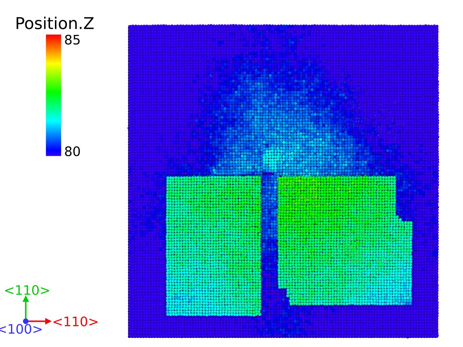
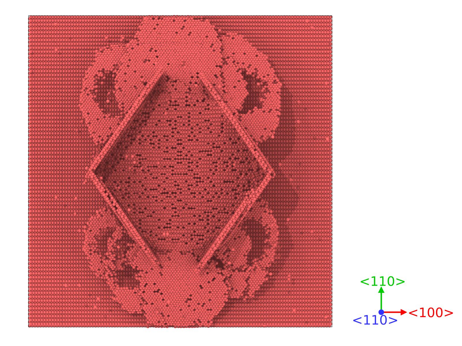
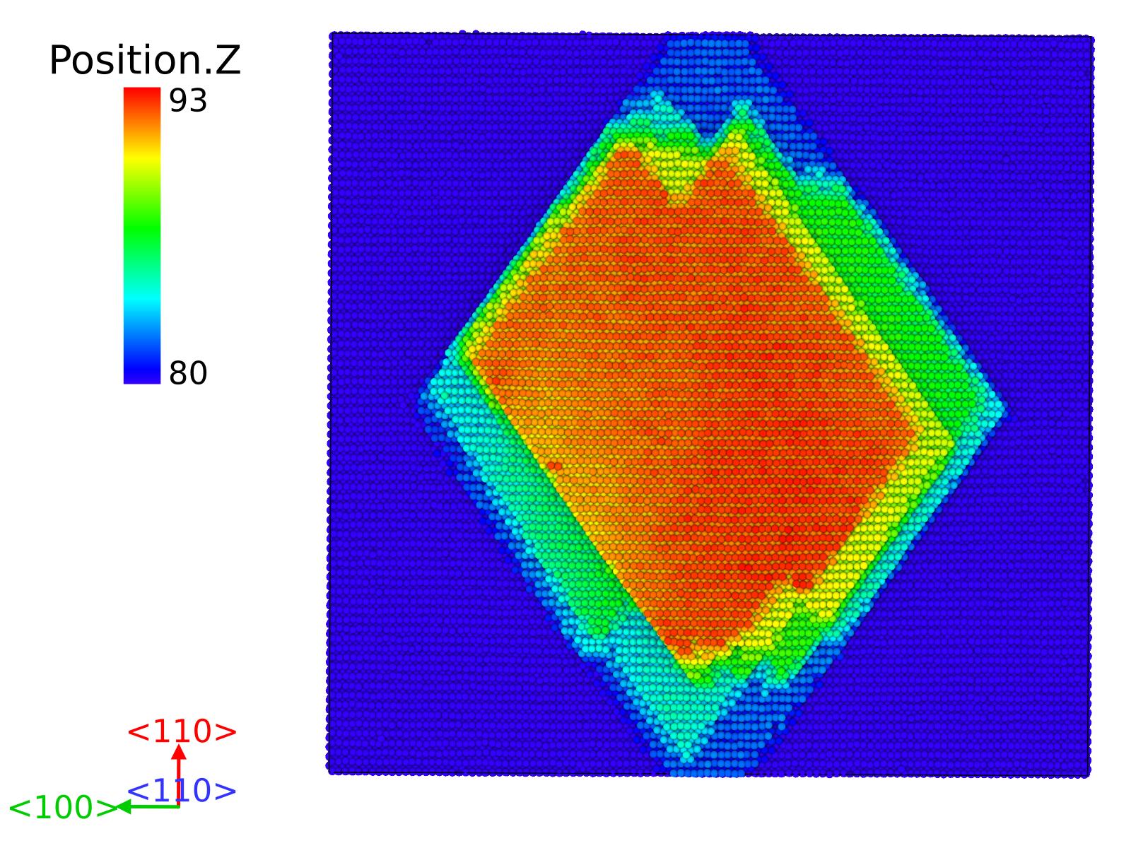
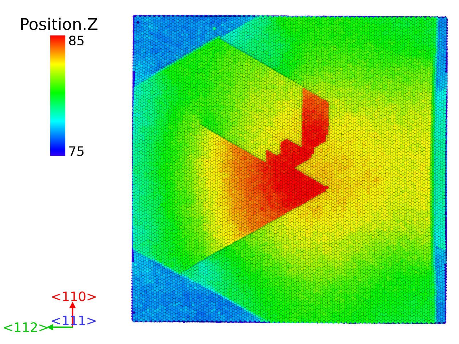
In Figure 4 we see that regardless the orientation of the surface, the protrusion is always created, but the shapes of these protrusions are different in all the cases. In the case of \hkl(110) surface (Figure 4 (a)) we see that the result is a diamond-shape protrusion. In the \hkl(100) surface (Figure 4 (b)), we observe an almost square shape as a product of the dislocation movement. For the \hkl(111) surface (Figure 4 (c)) we clearly see that the shape of the protrusion is circular. As we can check in Figures 4 (d-f), planes of stacking faults are formed differently between the disk void and the surface, where most of the stress in concentrated. We clearly see that most of the dislocations created are Shockley partials. The pressure originated by the bubble makes easier to slip the planes in those directions, creating the different orientations of the stacking faults planes respect to the surface. This leads us to see their relationship with the shape of the protrusion (Figures 4 (a-c)). In the \hkl(110) case (Figure 4 (a)), we realise that we have two superposed parallelograms where the lower angle is about 71∘, similarly as the one found by Pohjonen et al. [Poh13]. It corresponds to the angle between two different \hkl111 oriented planes, which are perpendicular to the \hkl(110) in the surface. Shockley dislocations are formed surrounding the staking faults and gliding towards the surface. We can see in Figure 4 (d) the nucleation of stair-rods dislocations in two Shockley partials, which interact with the surface configuring the acute corners of the rhomboid protrusion.
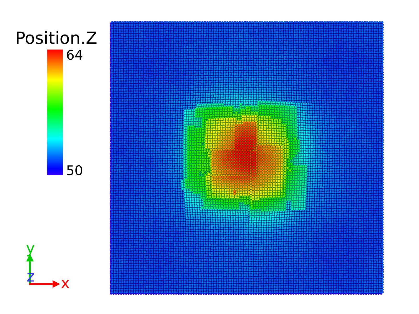
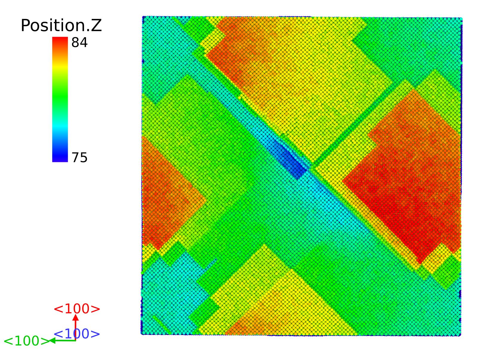
In the \hkl(100) case (Figure 4 (e)), we observe that the squared protrusion is induced by Shockley partial dislocations, that surround \hkl111-oriented planes that induce the changes in the surface. We know that out of the six \hkl100 planes, four of them have a 90∘ angle respect the \hkl(111) orientation, that explains the shape of the squared-shape protrusion created by the upcoming dislocations from the edge of the bubble.
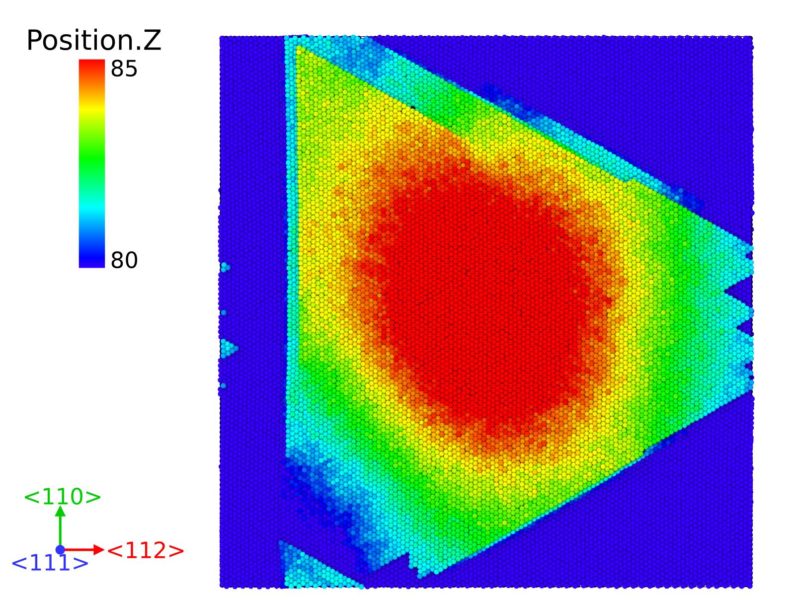
In the \hkl(111) case (Figure 4 (f)), we see that there are Shockley partial dislocations parallel to the surface orientation, that explains the circular shape of the protrusion. We also observed a prismatic loop that right under the surface (see Figure 5).
3.3 Disk-shape bubble
In this cell, the distance from the top of the bubble to the surface of the cell is twice larger than in the previous cell, and in this case, we introduced two densities, nH/Vac=1.2 and 2. We observe that, when increasing the distance of the void from the surface, at the lower H concentration, the effect is negligible. This changes when we introduce 2 H atoms per Cu missing atoms (nH/Vac=2) for 100 ps.
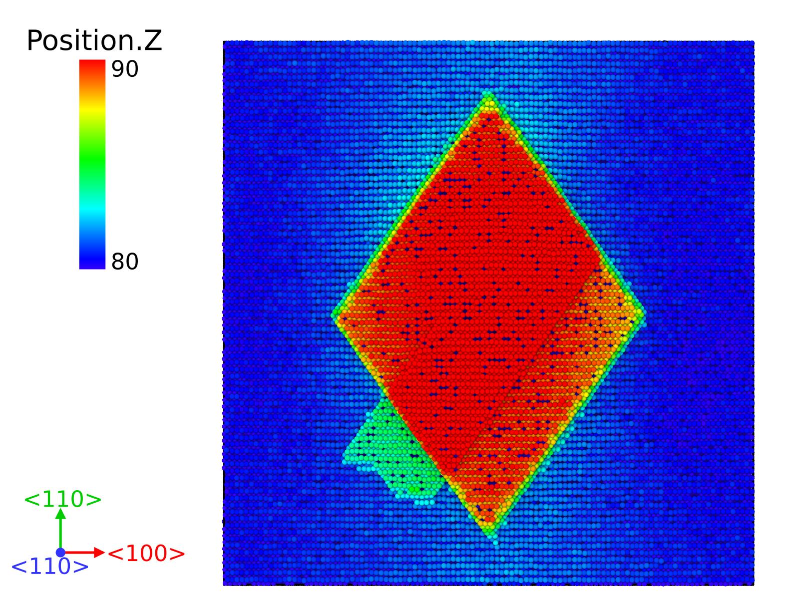
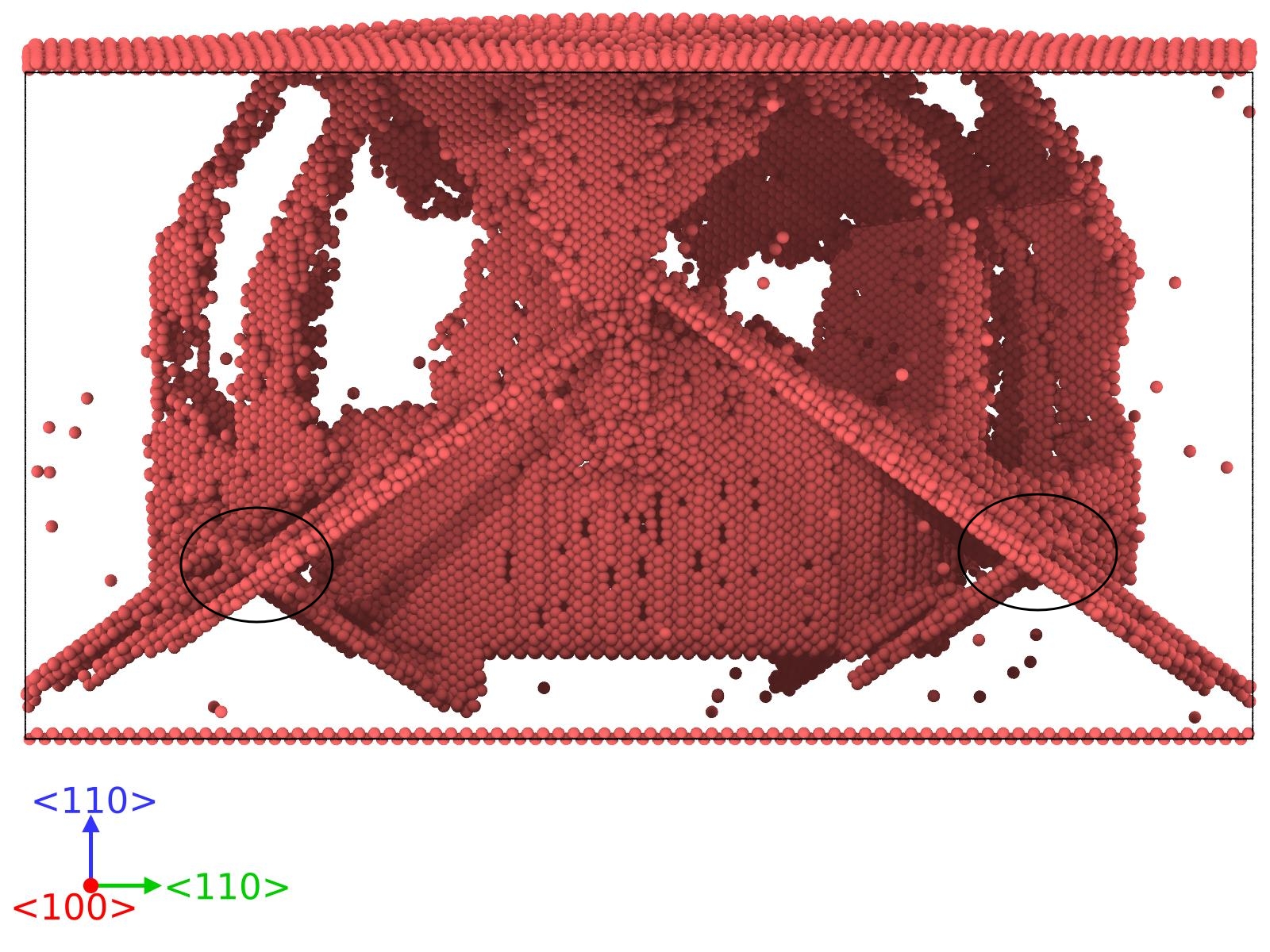
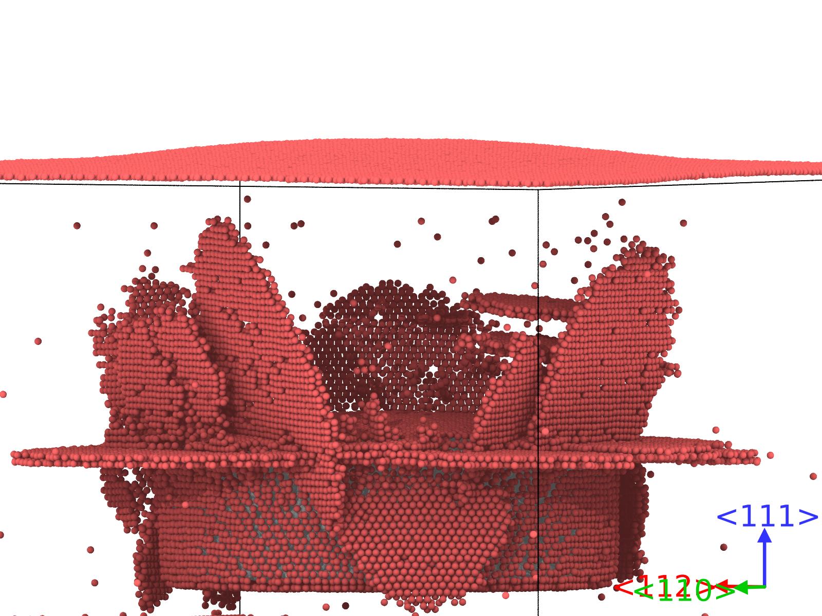
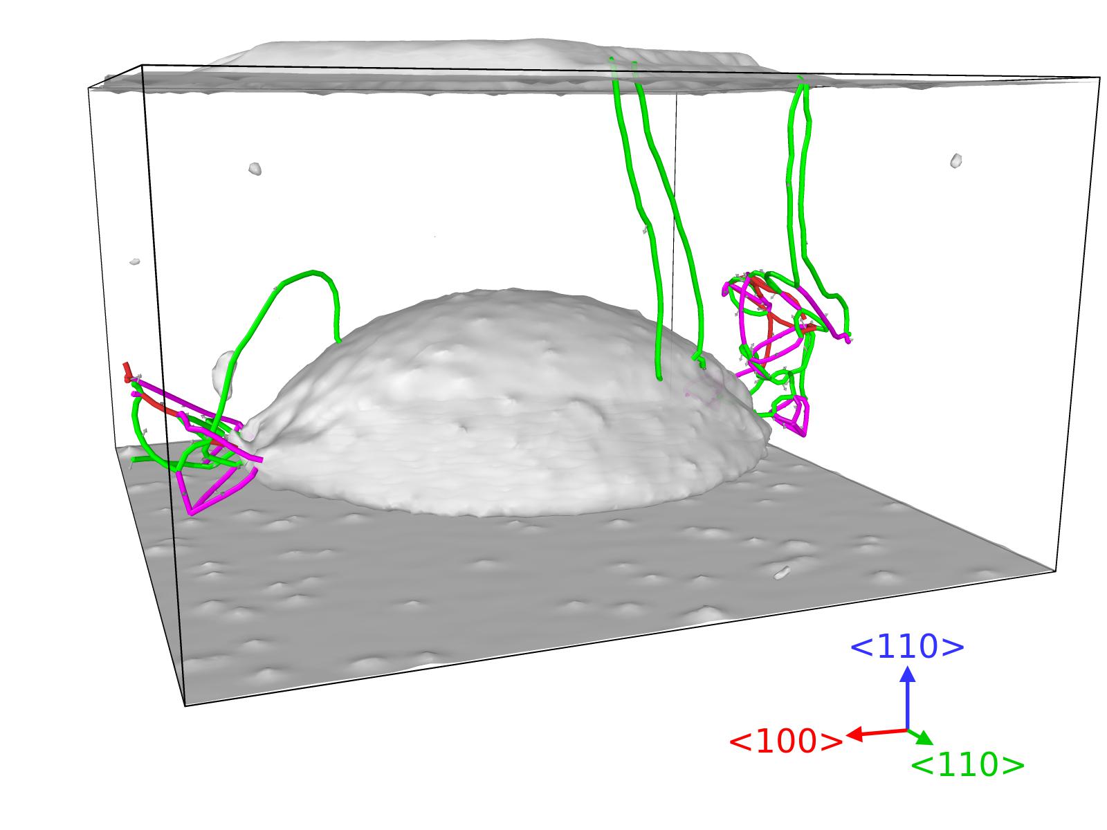
In Figure 6 (a) we observe that the surface yields similarly as in Figure 4 (a), corresponding to the \hkl(110) surface. Following the evolution of the simulation (see Figure 7 (a) and high110-n2-disloc.mp4), we observed that in the first steps of the simulation, a number of shear dislocations are created and they induce the protrusion in the surface (see the stacking faults created in Figure 8), similarly as they were created in the case exposed in Figure 4 (d). We can see that the rhomboid protrusion is delimited by the \hkl¡112¿ directions. The angles of the rhomboid are 71∘ and 109∘. However, we observed that using this larger cell with a concentration nH/Vac= 1.2 , nothing remarkable happened in the surface, despite the generation of dislocations beneath it (see high110-n1p2-disloc.mp4). We only noticed that at the end of the simulation, some shear dislocations that were created during the initial stages, are dissipated by then. We observe that in the shorter cell, the surface is sufficiently close to the void for generating the protrusion (see Figure 4 (a)).
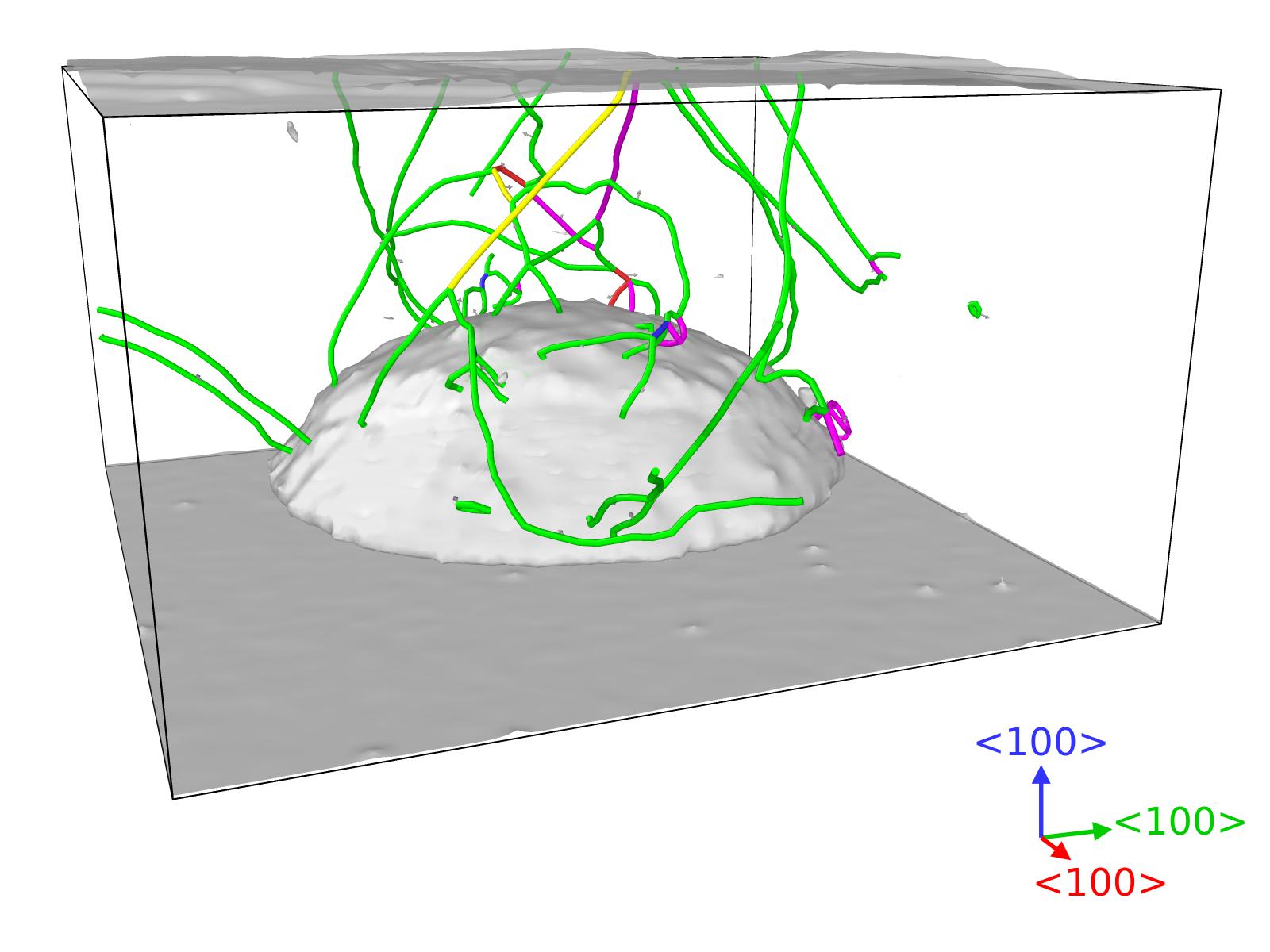
For the \hkl(100) surface shown in Figure 6 (b), the shape of the protrusion created is similar to the one created in Figure 4 (b) (see high100-n2-disloc.mp4). The mechanism behind the surface modification is the same as in the smaller cell with lower H density. We clearly observe how the shape of this protrusion is the product of the superposition of several squares. These squares are delimited by the Shockley partials that reach the surface, forming the borders of the protrusions oriented in the different \hkl¡110¿ directions. The dislocations glide in the \hkl111 planes due to the bubble exerted pressure, and when interact with the surface, they move upwards some atom layers as can be seen in Figure 7 (b), creating the final protrusion. In the nH/Vac= 1.2 case, no dislocation survives (see high100-n1p2-disloc.mp4).
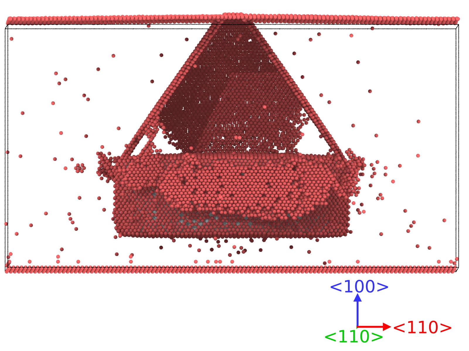
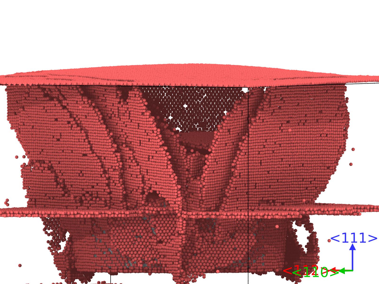
The \hkl(111) surface can be seen in Figure 6 (c), where we observe a triangle shape protrusion, which differs from the circular shape observe in Figure 4 (c). However, we also notice that the height of the atoms in the center marked by the triangle, is higher. This shows that the protrusion created in Figure 4 (c), due to the smaller pressure inside the void, may be not fully developed. Increasing the pressure and the distance to the surface, the process is more complex (see Figure 7 (c) and high111-n2-disloc.mp4). The dislocations (Shockley partials) cut the surface creating that triangle shape. We also observe that in the center, the protrusion is higher as product of the loop that grew below it. In the nH/Vac= 1.2 case for the \hkl(111) surface, some dislocations are created but not enough to modify the surface (see high111-n1p2-disloc.mp4).
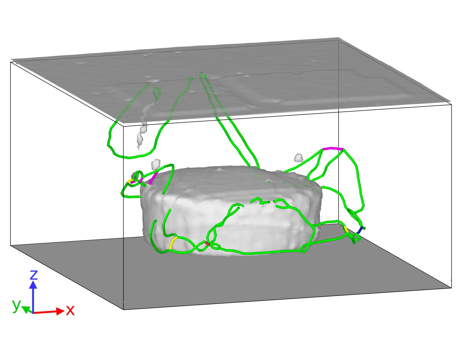
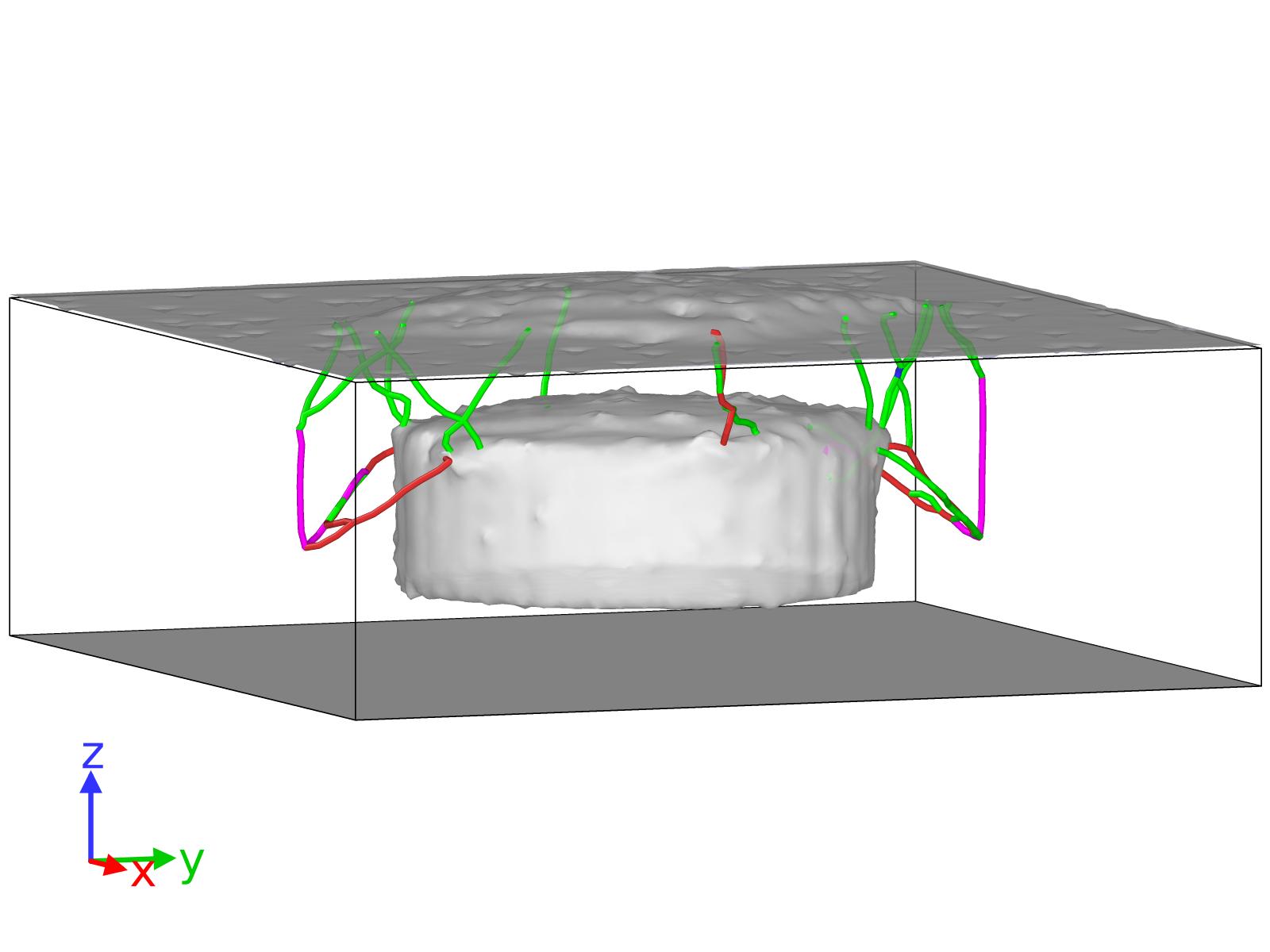
Following the evolution of \hkl(110) case, we observe that initially (after 2.5 ps) some dislocations are formed in the top border of the bubble. These partial dislocations () surround stacking faults that grow differently: some of them continue to the bottom of the cell (from the top surface of the bubble) and meet other plane which prevent the growing of the latter plane upwards (see Figure 8 (a,b), black circles). In Figure 8 (c,d), we see how the stacking fault planes grow perpendicular to the bubble flat surface. Their expansion from the border form the eventual diamond shape that is observed in Figure 6 (a).
The \hkl(100) case shows how the top border of the bubble starts to emit partial dislocations, leaving stacking faults planes that grows to the surface of the cell. In this case we clearly see the formation of the upper part of the stacking fault octahedron (Figure 9), which yields due to the high pressure; and the expansion of the dislocations forming it induces the change formed in the surface at the end of the simulation (see Figure 6 (b)).

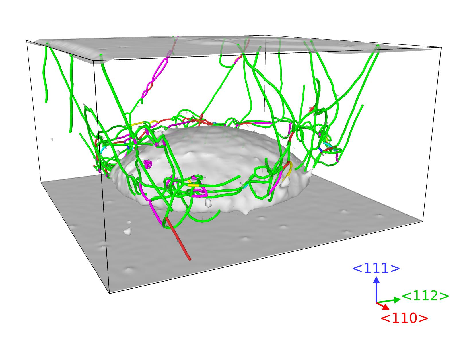
In the \hkl(111) case, the effect of the pressurized bubble creates stacking faults at the border of the bubble parallel to surface of the bubble, but also towards the surface as can be observed in Figure 10. We notice that these partial dislocation leading the planes to the surface are the responsible for the the triangle shape observed in the Figure 6 (c).
3.4 Hemisphere-shape bubble
We study in a similar cell as in the Section 3.3 the effect of a hemispherical bubble at nH/Vac=2.
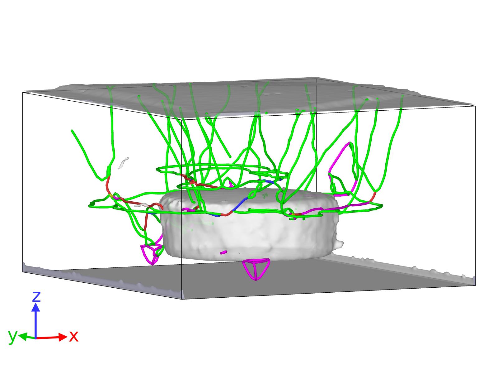
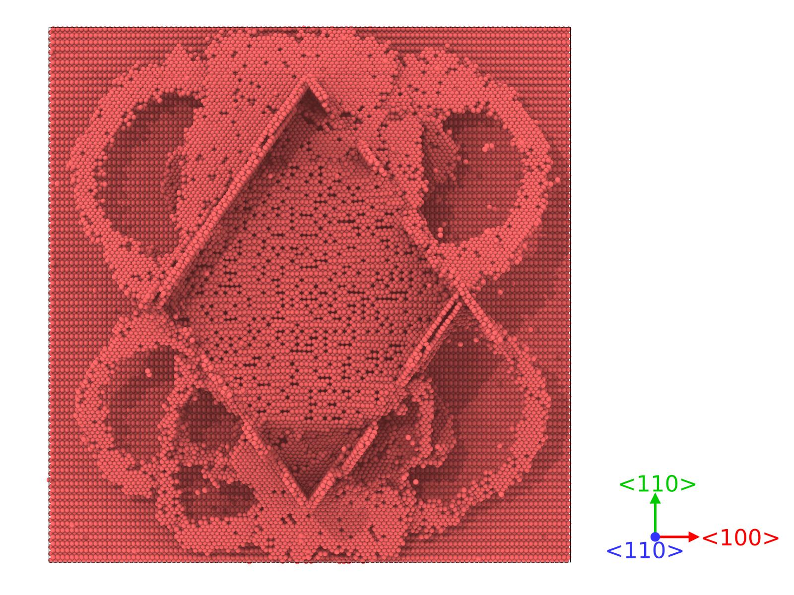
In Figure 11 we consider the final form of the differently oriented surfaces under the hemispheric bubble. We clearly observe that shape of the protrusions are similar as in Figure 6, however there are some remarkable differences. We see that in the \hkl(110) surface (Figure 11 (a)) the hemispheric bubble creates a clear superposition of rhomboid protrusions as the one observed in the disk bubble (see Figure 6 (a)). In the \hkl(100) surface (Figure 11 (b)), we see several protrusions in the with square shape, as a product of the dislocations emitted from the bubble in the \hkl¡110¿ directions. In Figure 11 (c) we notice that as in the disk-bubble case for the \hkl(111) case, we see the formation of triangular protrusions in the surface, where reach the larger height in the center(see Figure 4 (c)).
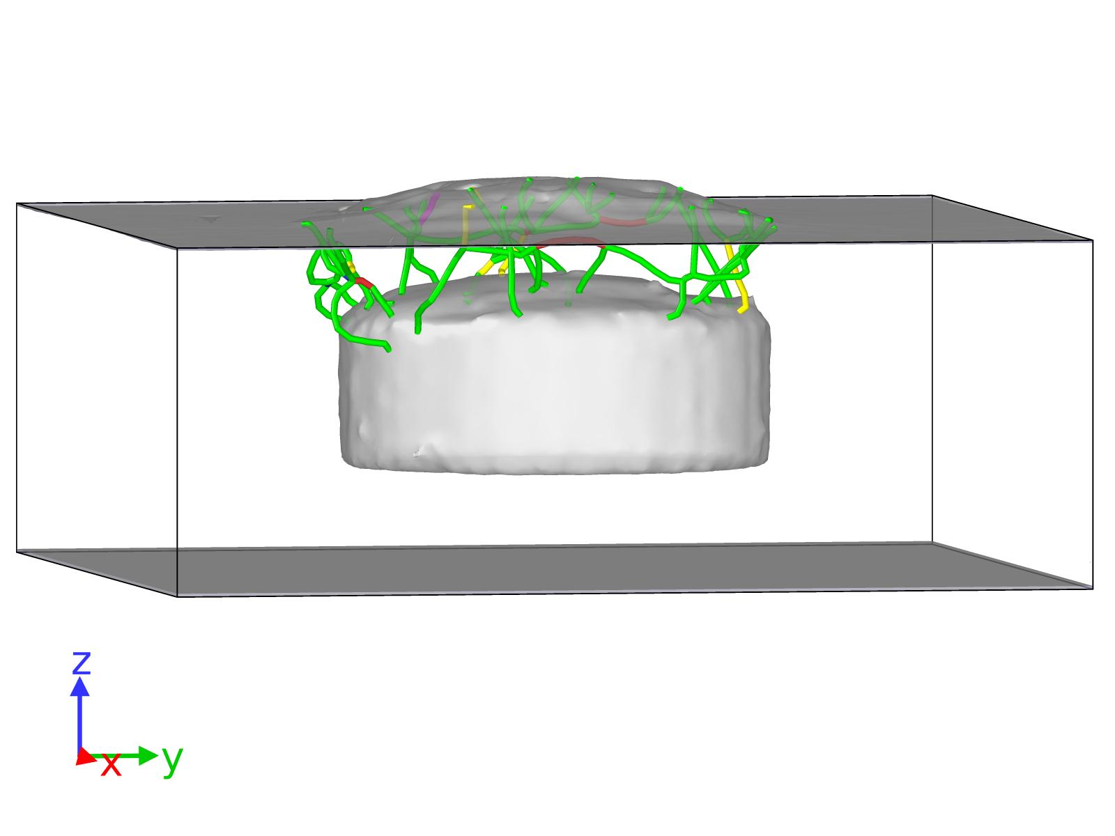
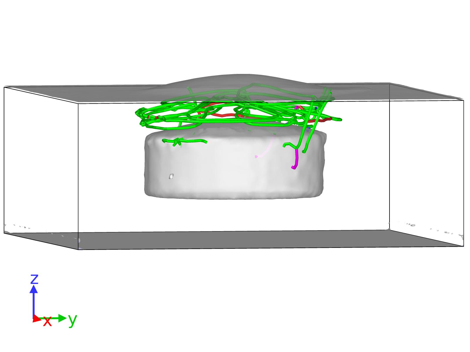
In this case we also follow the dislocation network created in these cells. We notice that the part of the bubble of maximum stress is the bottom edge of the bubble, where generally all the dislocations starts at the beginning of the simulations.
In the \hkl(110) case (see movie 110-hemisphere-n2.mp4 and Figures 11 (a) and 12 (a)), we see how the leading partial dislocations start to develop from the edge of the bubble and grow towards the surface. These dislocations expand in the four different \hkl111 planes that eventually form the rhomboid shape of the protrusions, once they are absorbed by the surface. In this case, we observe that the process occur with more strength than in the disk bubble case, since several parallel atomic planes in the \hkl111 planes creates the final rhomboid protrusion.
Considering the \hkl(100) case (see movie 100-hemisphere-n2.mp4 and Figures 11 (b) and 12 (b)), we observe that most of the dislocations start at the bottom edge, but some of them develop from parts higher in the bubble. These dislocations try to for the upper part of the stacking fault octahedron, but due to the high pressure, it does not entirely form, contrarily to the disk bubble case (see Figure 9). These dislocations form the eventual squared protrusion in the \hkl(100) surface.
The case corresponding to the \hkl(111) surface (see movie 111-hemisphere-n2.mp4 and Figures 11 (c) and 12 (c)), we observe that the leading partials starts to grow from the bubble, in some cases parallel to the surface from the upper part of the void and, at the same time, others start from the edge. These latter dislocations will form the triangular shape shown in Figures 11 (c), which in this case, is left a part of the atoms in the center of the protrusion slightly more elevated than the rest, reminding to the shape observed in the smaller cell containing a disk-shaped bubble (see Figure 4 (c)).
4 Discussion


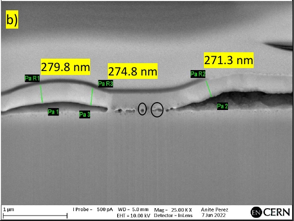
In Figure 13 (a) we observe how the penetration depth is larger in the \hkl¡110¿ direction (4 056 Å). For \hkl¡100¿ (2 710 Å)and \hkl¡111¿ (2 775 Å), we see that they are lower than for \hkl¡110¿, but rather similar to each other. We verify that in the Cu sample, the blisters formed close to the surface are at roughly the same distance in the \hkl(100) and \hkl(111) grains (3 000 Å). We see that in the \hkl¡111¿ direction, the ions loose energy faster than in the \hkl¡100¿, which may explain the difference in the blister/protrusion density between the two grains, since the voids generated in the former can be smaller. This means that higher fluences are needed to obtain larger bubbles in order to reach higher densities of protrusions as in \hkl¡100¿-oriented grains. The similar penetration depth of H at this energy is consistent with Moreno et al. work [moreno1997], where they found a similar stopping power for He in differently oriented Cu.
Moreover, we see that the shapes of the protrusions observed in Figure 13 (b) are in agreement with the obtained using MD for \hkl(100) and \hkl(111). In the case of the \hkl(100) grain, is easy to identify the square shape among the protrusions formed in the surface (see Figures 4 (b) and 11 (b)). In some cases we observe that the protrusions has merged, producing slightly different shapes. In the case of the \hkl(111) grain, we observe rather circular shapes (see Figures 3 and 13 (b)), which are in agreement with the ones predicted by MD (Figures 4 (c) and 11 (c)).
Furthermore, we observe how the effect in the surface is similar regardless of the shape of the bubble. We see that in the both forms studied, the yielding points of the bubbles are those where the change of curvatures is larger i.e., the borders joining the flat surfaces with the curved ones. The growth of the bubble is done via emission of dislocations [Lop21], and these dislocations interact with the surface inducing the protrusions that are experimentally observed. The simulated bubbles are considerably smaller than the most noticeable ones observed in Figure 13 (b). However, the size of the smaller bubbles marked in Figures 13 (c-d), correspond to the ones simulated in this work.
We observe that the emission of dislocations for the disk-shaped bubble occurs at nH/Vac=2, however, in previous study [Lop21] it occurred at nH/Vac=3, while only minor defects were created around the spherical-shaped bubble. Many variables can change this evolution: the shape of the void might be determinant. The disk contains flat surfaces in two sides, and we have seen that the dislocations are created at the borders, where the change of curvature is larger. Moreover, the effect of the surface close to the bubble might affect this result compared with the results shown in Ref. [Lop21].
In the disk-shaped bubble simulations, the border acts as the yielding point of the bubble, regardless the surface orientation, and the dislocations are emitted mostly from there.
5 Conclusions
In this work we have shown experimentally the effect of 45 keV H- on Cu, performing the EBSD analysis and identifying the effect of this irradiation on differently oriented grains.
Furthermore, using MD, we simulated the effect of H in different bubble shapes, pointing out the mechanisms which lead the bubbles to grow via dislocations emission and modifying the surface, creating protrusions. The protrusions shown computationally are similar in shape to the observed experimentally.
We have seen that the shape of the bubble, regardless of small differences, they create similar effect in the surface.
We have developed a computational model to show the effect of pressurized bubbles under differently oriented surfaces, which agrees considerably well with the experimental evidence.
Acknowledgements
Computer time granted by the IT Center for Science – CSC – Finland and the Finnish Grid and Cloud Infrastructure (persistent identifier urn:nbn:fi:research-infras-2016072533) is gratefully acknowledged.
References
- [1] J. Condon and T. Schober J. of Nuclear Materials, vol. 207, pp. 1–24, 1993.
- [2] X. Bai, A. Voter, R. Hoagland, M. Nastas, and B. Uberuaga, “Efficient annealing of radiation damage near grain boundaries via interstitial emission,” Science, vol. 327, no. 5973, pp. 1631 – 1634, 2010.
- [3] R. Smirnov, S. Krasheninnikov, and J. Guterl, “Atomistic modeling of growth and coalescence of helium nano-bubblesin tungsten,” Journal of Nuclear Materials, vol. 463, no. 5973, pp. 359 – 362, 2015.
- [4] L. Yang, F. Gaoc, R. Kurtz, X. Zu, S. Peng, X. Long, and X. Zhou, “Effects of local structure on helium bubble growth in bulk and at grain boundaries of bcc iron: A molecular dynamics study,” Acta Materialia, vol. 97, no. 15, pp. 86 – 93, 2015.
- [5] D. Stewart, Y. Osetsky, and R. Stoller, “Atomistic studies of formation and diffusion of helium clusters and bubbles in BCC iron,” Journal of Nuclear Materials, vol. 417, no. 1 – 3, p. 1110, 2011.
- [6] M. Ganchenkova, Y. Yagodzinskyy, V. Borodin, and H. Hanninen, “Effects of hydrogen and impurities on void nucleation in copper: simulation point of view,” Philosophical Magazine, vol. 94, pp. 3522–3548, 2014.
- [7] P. Korzhavyi and R. Sandström, “Monovacancy in copper: Trapping efficiency for hydrogen and oxygen impurities,” Computational Materials Science, vol. 84, pp. 122–128, 2014.
- [8] K. O. E. Henriksson, K. Nordlund, and J. Keinonen, “Molecular dynamics simulations of helium cluster formation in tungsten,” Nucl. Instr. Meth. Phys. Res. B., vol. 244, pp. 377–391, 2006.
- [9] M. Thompson, P. Kluth, R. Doerner, N. Kirby, and C. Corr, “Probing helium nano-bubble formation in tungsten with grazing incidence small angle x-ray scattering,” Nucl. Fusion, vol. 55, p. 042001, 2015.
- [10] W. Wang, J. Roth, S. Lindig, and C. H. Wu, “Blister formation of tungsten due to ion bombardment,” J. Nucl. Mater., vol. 299, p. 124, 2001.
- [11] F. I. Allen, P. Hosemann, and M. Balooch, “Key mechanistic features of swelling and blistering of helium-ion-irradiated tungsten,” Scripta Materialia, vol. 178, pp. 256–260, 2020.
- [12] P. B. Johnson and D. J. Mazey, “The depth distribution of bubbles and fracture in he+ and d+ irradiated copper,” J. Nucl. Mater., vol. 111 & 112, pp. 681–686, 1982.
- [13] S. Nakahara and Y. Okinaka, “Defects induced in copper by cathodic charging of hydrogen,” J. Electrochem. Soc., vol. 136, p. 1892, 1989.
- [14] S. Taskaev, D. Kasatov1, A. Makarov, and I. Shchudlo, “In situ observations of blistering of a metal irradiated with 2 mev protons,” IPAC2018, Vancouver, 2018.
- [15] V. Barabash et al., “Armour Materials for the ITER Plasma Facing Components,” Phys. Scr., vol. 1999, p. T81, 1999.
- [16] R. Nygren, R. Raffray, D. Whyte, M. Urickson, M. Baldwin, and L. Snead, “Making tungsten work,” J. Nucl. Mater., vol. 417, p. 451–456, 2011.
- [17] Alvarez, J. et al., “The role of spatial and temporal radiation deposition in inertial fusion chambers: the case of HiPER,” Nucl. Fusion, vol. 51, p. 053019, 2011.
- [18] Kaufmann M. et al., “Tungsten as first wall material in fusion devices,” Fusion Eng. Des., vol. 82, p. 521–527, 2007.
- [19] R. A. Causey and T. J. Venhaus, “The use of tungsten in fusion reactors: a review of the hydrogen retention and migration properties,” Physica Scripta, vol. 2001, p. T94, 2001.
- [20] W. Pesch, T. Schober, and H. Wenzl Metall. Trans. A, vol. 11, p. 1821, 1980.
- [21] T. Schober, H. Conrads, and A. Schulz Fusion Technol., vol. 23, p. 227, 1993.
- [22] C. Ju and J. Rigsbee Mater. Sci. Eng., vol. 74, p. 47, 1985.
- [23] M. Iino Metall. Trans. A, vol. 9, p. 1581, 1978.
- [24] K. Ravi, V. Ramaswamy, and T. Namboodhiri Mater. Sci. Eng., vol. A129, p. 87, 1990.
- [25] J.-L. Lee and J.-Y. Lee J. Mater. Sci., vol. 22, p. 3939, 1987.
- [26] J.-Y. Lee and J.-L. Lee Phys. Chem. NF, vol. 146, p. 233, 1985.
- [27] J.-L. Lee and J.-Y. Lee Metall. Trans. A, vol. 20, p. 1793, 1989.
- [28] K. Kamada, A. Sagara, and H. Kinoshita, “Difficulty of dislocation-punching from densely distributed high pressure bubbles,” Radiation Effects, vol. 106:3, pp. 219–227, 1988.
- [29] K. Kamada, “Hydrogen implantation effects in the subsurface layer of aluminum - bubble pressure and surface modifications,” Journal of Nuclear Materials, vol. 169, pp. 141–150, 1989.
- [30] L. Milacek and R. Daniels J. Appl. Phys., vol. 39, p. 5714, 1968.
- [31] L. Milacek and R. Daniels J. Appl. Phys., vol. 39, p. 2803, 1968.
- [32] R. Daniels J. Appl. Phys., vol. 39, p. 417, 1971.
- [33] D.-G. Xie, Z.-J. Wang, J. Sun, J. Li, E. Ma, and Z.-W. Shan, “In situ study of the initiation of hydrogen bubbles at the aluminium metal/oxide interface,” Nature Materials, vol. 14, p. 899–903, 2015.
- [34] M. Sznajder, U. Geppert, and M. Dudek, “Hydrogen blistering under extreme radiation conditions,” npj Materials Degradation, vol. 2, p. 1, 2018.
- [35] S. Nakahara and Y. Okinaka, “Microstructure and mechanical properties of electroless copper deposits,” Ann. Rev. Mater. Sci., vol. 21, p. 93, 1991.
- [36] M. Fukui, R. Sakamoto, K. Araki, T. Fujiwara, T. Muroga, and N. Yoshida, “In situ observation of low energy hydrogen ion irradiation damage in copper,” J. of Nuclear Mat., vol. 220-222, pp. 810–814, 1995.
- [37] A. Robinson, P. Edmondson, C. English, S. Lozano-Perez, G. Greaves, J. Hinks, S. Donnelly, and C. Grovenor, “The effect of temperature on bubble lattice formation in copper under in situ he ion irradiation,” Acta Materialia, vol. 131, pp. 08–111, 2017.
- [38] The Compact Linear Collider Study, http://clic-study.web.cern.ch/clic-study/.
- [39] S. Barengolts, V. Mesyats, V. Oreshkin, E. Oreshkin, K. Khishchenko, I. Uimanov, and M. Tsventoukh, “Mechanism of vacuum breakdown in radio-frequency accelerating structures,” Phys. Rev. Accel. Beams, vol. 21, p. 061004, 2018.
- [40] A. Kyritsakis, M. Veske, K. Eimre, V. Zadin, and F. Djurabekova, “Thermal runaway of metal nano-tips during intense electron emission,” J. of Physics D: Applied Physics, vol. 51, p. 22, 2018.
- [41] K. Nordlund and F. Djurabekova, “Defect model for the dependence of breakdown rate on external electric fields,” Phys. Rev. ST Accel. Beams, vol. 15, p. 071002, 2012.
- [42] E. Z. Engelberg, Y. Ashkenazy, and M. Assaf, “Stochastic model of breakdown nucleation under intense electric fields,” Phys. Rev. Lett., vol. 120, p. 124801, 2018.
- [43] A. Descoeudres, Y. Levinsen, S. Calatroni, M. Taborelli, and W. Wuensch Phys. Rev. ST Accel. Beams, vol. 12, p. 092001, 2009.
- [44] A. Descoeudres, F. Djurabekova, and K. Nordlund, “Dc breakdown experiments with cobalt electrodes,” CLIC-Note, vol. 875, pp. 1–6, 2011.
- [45] P. N. Burrows, N. C. Lasheras, L. Linssen, M. Petric, A. Robson, D. Schulte, E. Sicking, and S. Stapnes, “Vol. 2 (2018): The compact linear collider (clic) - 2018 summary report,” doi: https://doi.org/10.23731/CYRM-2018-002, 2018.
- [46] A. Lopez-Cazalilla, F. Djurabekova, F. Granberg, K. Mizohata, A. T. Perez-Fontela, S. Calatroni, and W. Wuensch, “Punching of arbitrary face prismatic loops from hydrogen nanobubbles in copper,” Acta Materialia, vol. 225, p. 117554, 2022.
- [47] Q. Sun, Y. Ni, and S. Wang, “Orientation dependence of dislocation structure in surface grain of pure copper deformed in tension,” Acta Materialia, vol. 203, p. 116474, 2021.
- [48] N. Hansen, X. Huang, and G. Winther, “Effect of grain boundaries and grain orientation on structure and properties,” Metall Mater Trans A, vol. 42, p. 613–625, 2011.
- [49] P. Heino, H. Hakkinen, and K. Kaski, “Molecular-dynamics study of mechanical properties of copper,” Europhys. Lett., vol. 41 (3), pp. 273–278, 1998.
- [50] L. Wang, J. Sun, Q. Li, Z. Li, and Y. Zheng, “Coupling effect of twin boundary and void on the mechanical properties of bulk nanotwinned copper: an atomistic simulation,” Journal of Physics D: Applied Physics, vol. 52, p. 5, 2018.
- [51] L. E., N. L., S. H, and Z. D., “Molecular dynamics study on the nano-void growth and coalescence at grain boundary,” Sci. China Phys. Mech. Astron., vol. 55, p. 86–93, 2012.
- [52] Z. Yang, G. Zhang, and J. Zhao, “Molecular dynamics simulations of void effect of the copper nanocubes under triaxial tensions,” Physics Letters A, vol. 380, no. 7, pp. 917–922, 2016.
- [53] E. T. Seppälä, J. Belak, and R. E. Rudd, “Onset of void coalescence during dynamic fracture of ductile metals,” Phys. Rev. Lett., vol. 93, p. 245503, 2004.
- [54] E. T. Seppälä, J. Belak, and R. E. Rudd, “Three-dimensional molecular dynamics simulations of void coalescence during dynamic fracture of ductile metals,” Phys. Rev. B, vol. 71, p. 064112, 2005.
- [55] K. Nordlund, J. Keinonen, E. Rauhala, and T. Ahlgren, “Range profile in self-ion-implanted crystalline si,” Phys. Rev. B, vol. 52, p. 15170, 1995.
- [56] Y. Mishin, M. Mehl, D. Papaconstantopoulos, A. Voter, and J. Kress, “Structural stability and lattice defects in copper: Ab initio, tight-binding, and embedded-atom calculations,” Physical Review B, vol. 63, no. 22, 2001.
- [57] S. Foiles, M. Baskes, C. Melius, and M. Daw, “Calculation of hydrogen dissociation pathways in nickel using the embedded atom method,” J. of Less-Common Metals, vol. 130, pp. 465–473, 1987.
- [58] M. I. Baskes, S. Foiles, and C. Melius, “Dynamical calculation of low hydrogen reemission off hydrogen covered surfaces,” J. of Nuclear Materials, vol. 145-147, pp. 339–343, 1987.
- [59] J. E. Angelo, N. R. Moody, and M. I. Baskes, “Trapping of hydrogen to lattice defects in nickel,” Modelling and Simulation in Materials Science & Engineering, vol. 3, pp. 289–307, 1995.
- [60] J. F. Ziegler, J. P. Biersack, and U. Littmark, The Stopping and Range of Ions in Matter. New York: Pergamon, 1985.
- [61] H. J. C. Berendsen, J. P. M. Postma, W. F. van Gunsteren, A. DiNola, and J. R. Haak, “Molecular dynamics with coupling to external bath,” J. Chem. Phys., vol. 81, no. 8, p. 3684, 1984.
- [62] E. Fromm, W. Hehn, G. Hörz, and H. Jehn, Gases and carbon in metals. Physics data, Eggenstein-Leopoldshafen: Karlsruhe Fachinformationszent. Kernforsch. Zentralstelle At. Energ., 1984.
- [63] A. Stukowski, “Visualization and analysis of atomistic simulation data with ovito – the open visualization tool,” Modelling Simul. Mater. Sci. Eng., vol. 18, p. 015012, 2010.
- [64] C. L. Kelchner, S. J. Plimpton, and J. C. Hamilton Phys. Rev. B, vol. 58, p. 11085, 1998.
- [65] A. Stukowski, V. Bulatov, and A. Arsenlis, “Automated identification and indexing of dislocations in crystal interfaces,” Modelling Simul. Mater. Sci. Eng., vol. 20, p. 085007, 2012.
- [66] K. Nordlund, “Molecular dynamics simulation of ion ranges in the 1 – 100 kev energy range,” Comput. Mater. Sci., vol. 3, p. 448, 1995.
- [67] J. F. Ziegler, J. P. Biersack, and M. D. Ziegler, SRIM - The Stopping and Range of Ions in Matter. Chester, Maryland, USA: SRIM Co., 2008.
- [68] J. Jussila, F. Granberg, and K. Nordlund, “Effect of random surface orientation on w sputtering yields,” Nuclear Materials and Energy, vol. 17, pp. 113–122, 2018.
- [69] A. S. Pohjonen, S. Parviainen, T. Muranaka, and F. Djurabekova, “Dislocation nucleation on a near surface void leading to surface protrusion growth under an external electric field,” J. Appl. Phys., 2013.
- [70] D. Moreno and D. Eliezer, “On the blister formation in copper alloys due to the helium ion implantation,” Metall. Mater. Trans. A, vol. 28, p. 755–762, 1997.
Supplementary material for ”Hydrogen accumulation in copper”
S0.1 Volume & Dislocation analysis
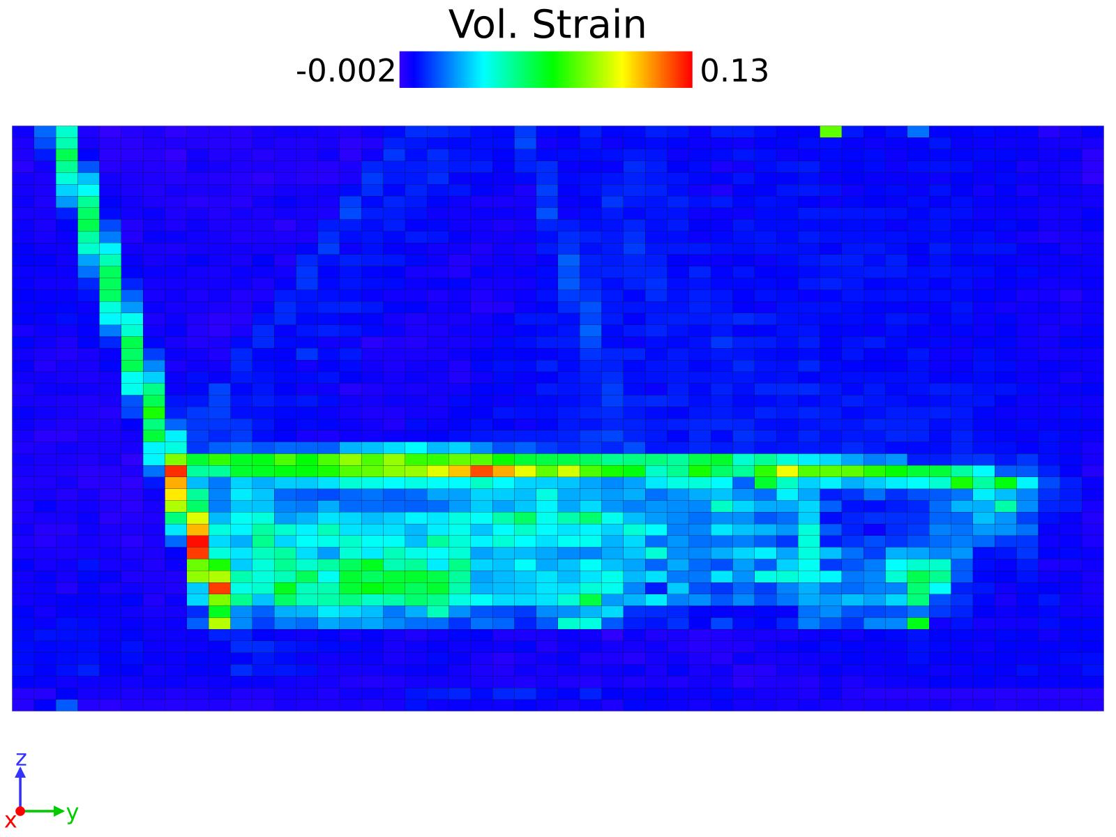
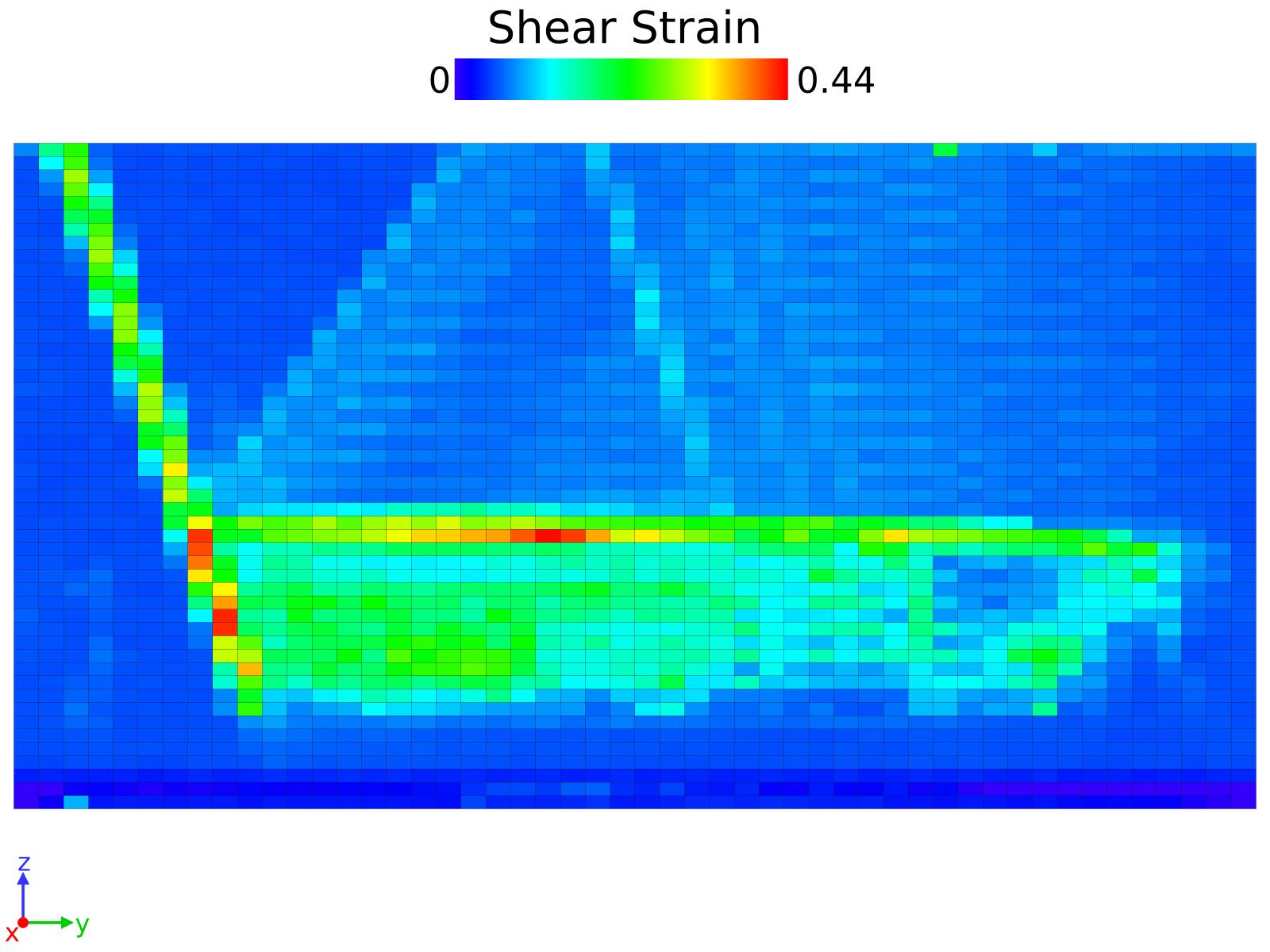
The evolution of the volume change in the bubble, defined as , is followed using the Construct Surface Mesh from OVITO. For that, we do not consider the H atoms in the bubble. We also compute the strain using Atomic Strain feature from OVITO, using a cutoff of 2.8 Å. For the histograms, the Spatial binning feature was used applying 50 bins in each of the 2 dimensions represented and 1 in the perpendicular to the plane. The mean value in the bin is represented.
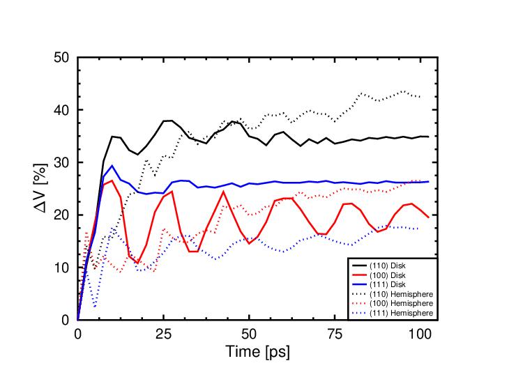
When comparing both bubble types containing the same pressure, we see observe several differences. In the volume change (Figure S1 (a)), we see that it is larger in the \hkl(110) case for both bubbles, however the hemisphere case has a slower increase leading to higher change eventually. The \hkl(100) cases show a considerable discrepancy between the two bubbles in their evolution. The disk shows a breathing evolution of the volume and, on the other hand, the hemisphere shows a stable increase of the volume change. The \hkl(111)-oriented surfaces show less fluctuations but the highest discrepancy in the total change. We see that the dislocations grow on the border similarly in all the cases. However, the orientation of the surface plays a role absorbing them, being this effect greater in the \hkl(111) case, where some large stacking faults planes are in contact with the surface of the bubble and the surface of the cell, in the disk-bubble case.
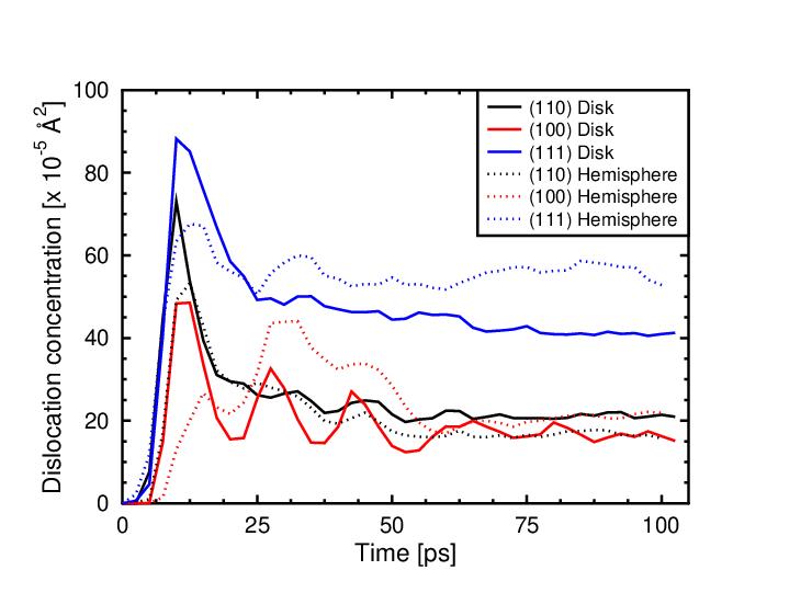
In Figure S1 (b) we see the dislocation concentration in each case. We do not see clear differences between the two geometries. On the other hand, the \hkl(111) cases provide the highest concentration in both cases.
S1 Stress-strain Analysis
We include information extracted from the stress and strain tensor.
| Disk | Hemisphere | Disk | Hemisphere | ||
|---|---|---|---|---|---|
| e | |||||
| e | |||||
| e | |||||
| e | |||||
| e | |||||
| e |
From the volumetric stress, we can see that the larger hydrostatic strain is observed in the \hkl(110) case, something that can be observed from the volume change in Figure S1 (a). Conversely, the change is smaller in the \hkl(100) and the smallest is for the \hkl(111). On the other hand, when we analyse the dislocation density, we observe that, regardless of the difference of values between the cases, all reach a maximum about 10 ps. From that moment the protrusion starts to be visible in all the cases. The reason of this is that the dislocations have reached the surface, shifting the atoms in the z-direction, however, differently depending on the surface orientation.
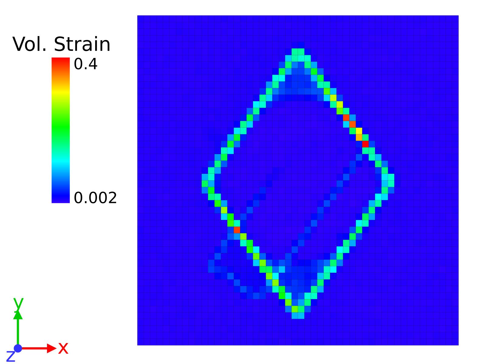
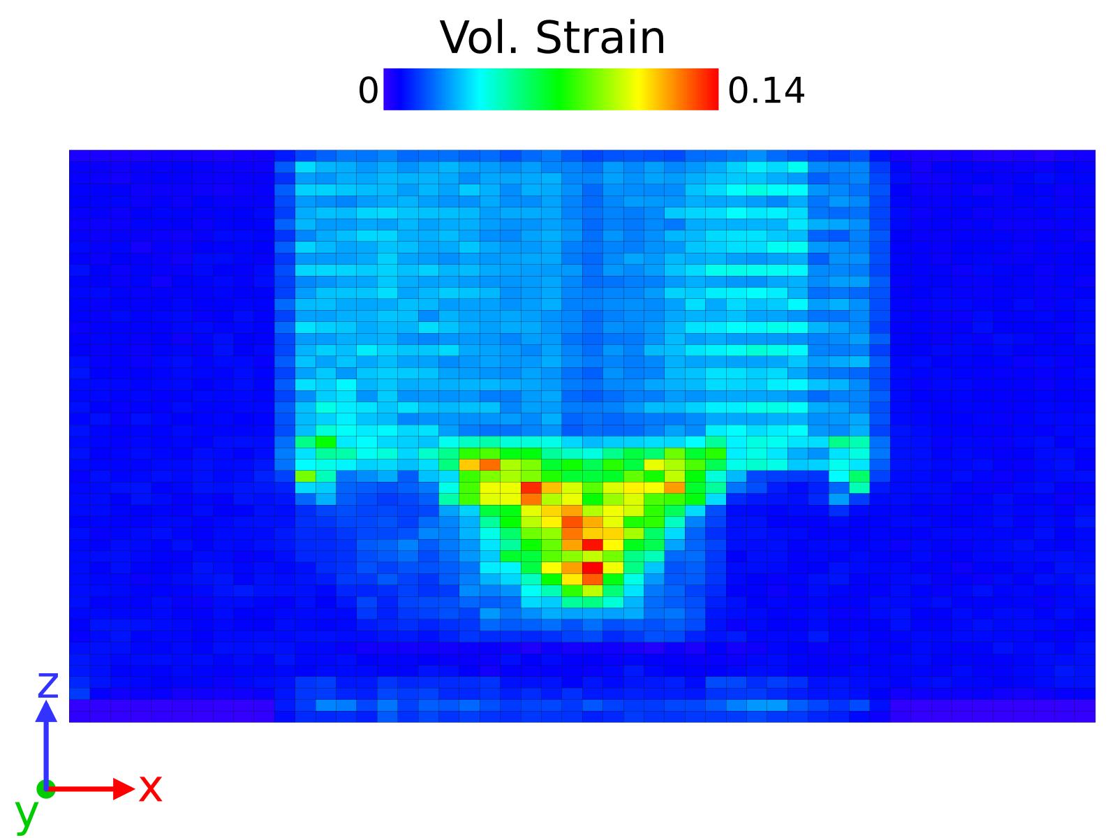
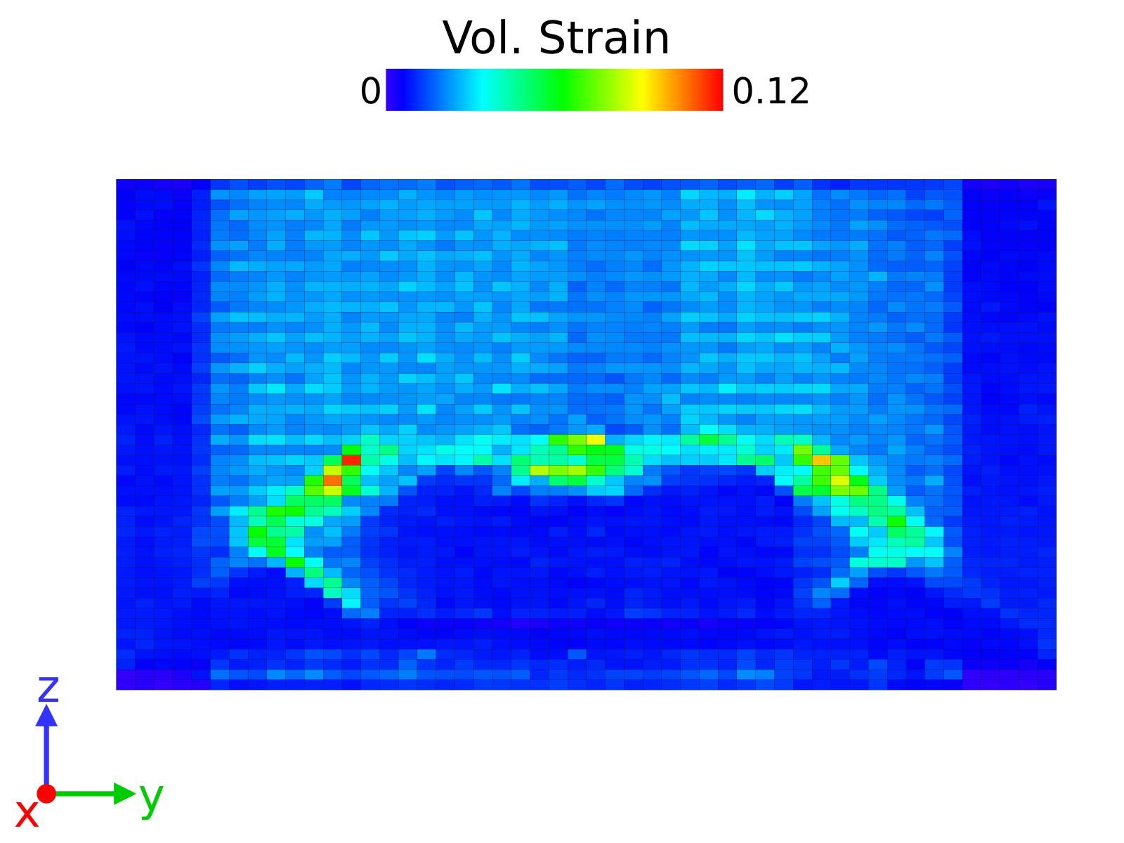
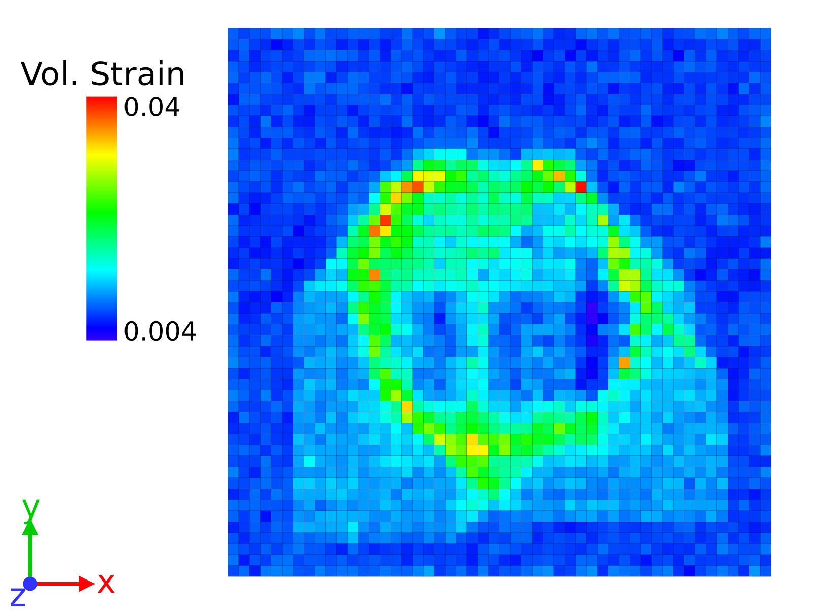
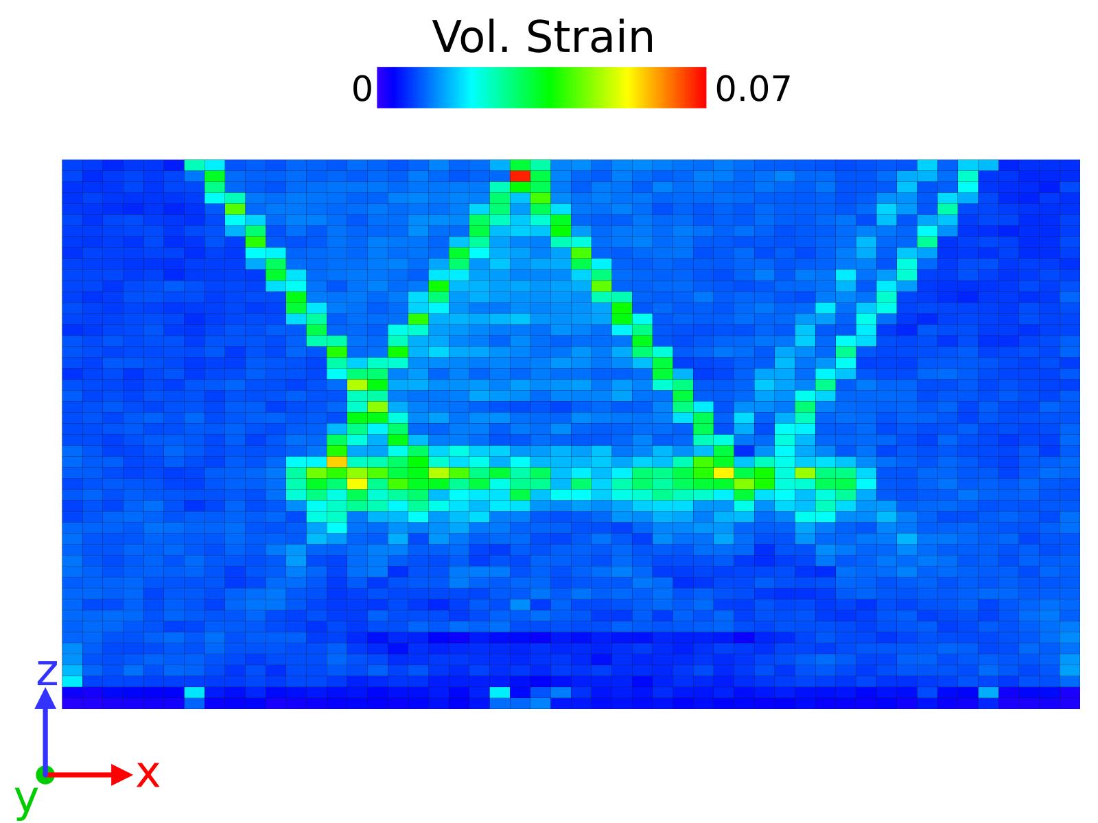
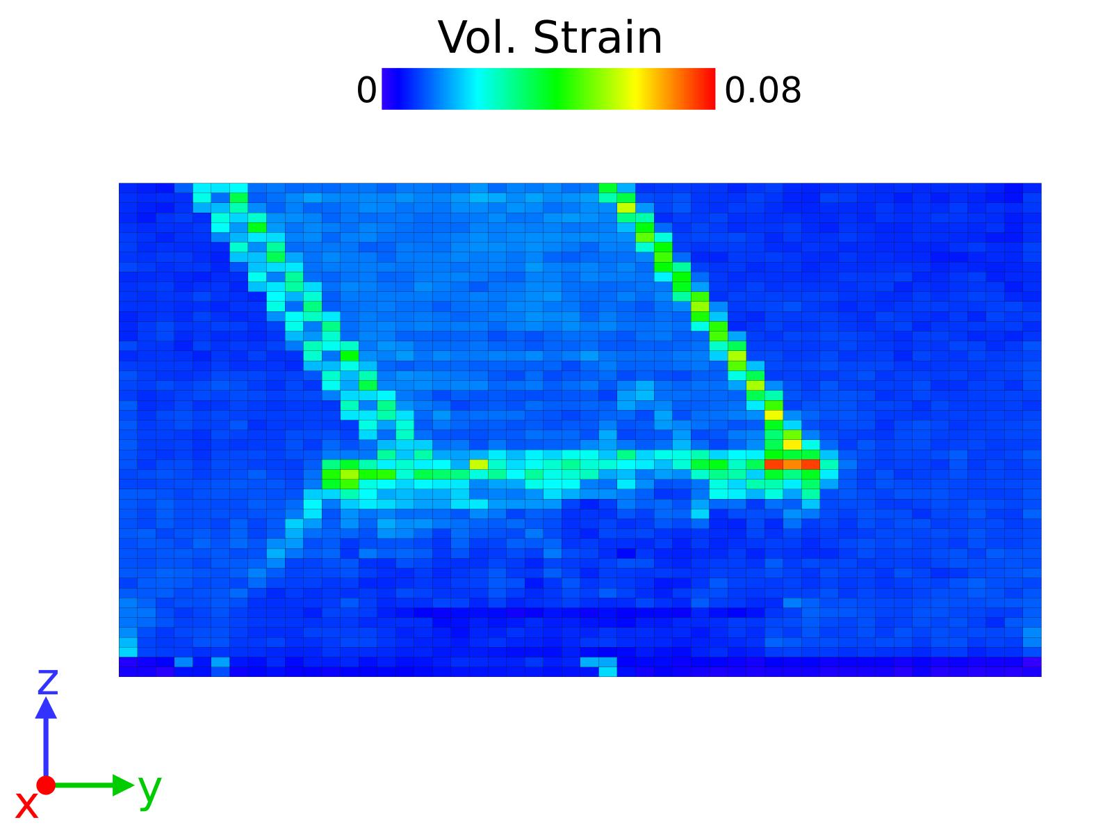
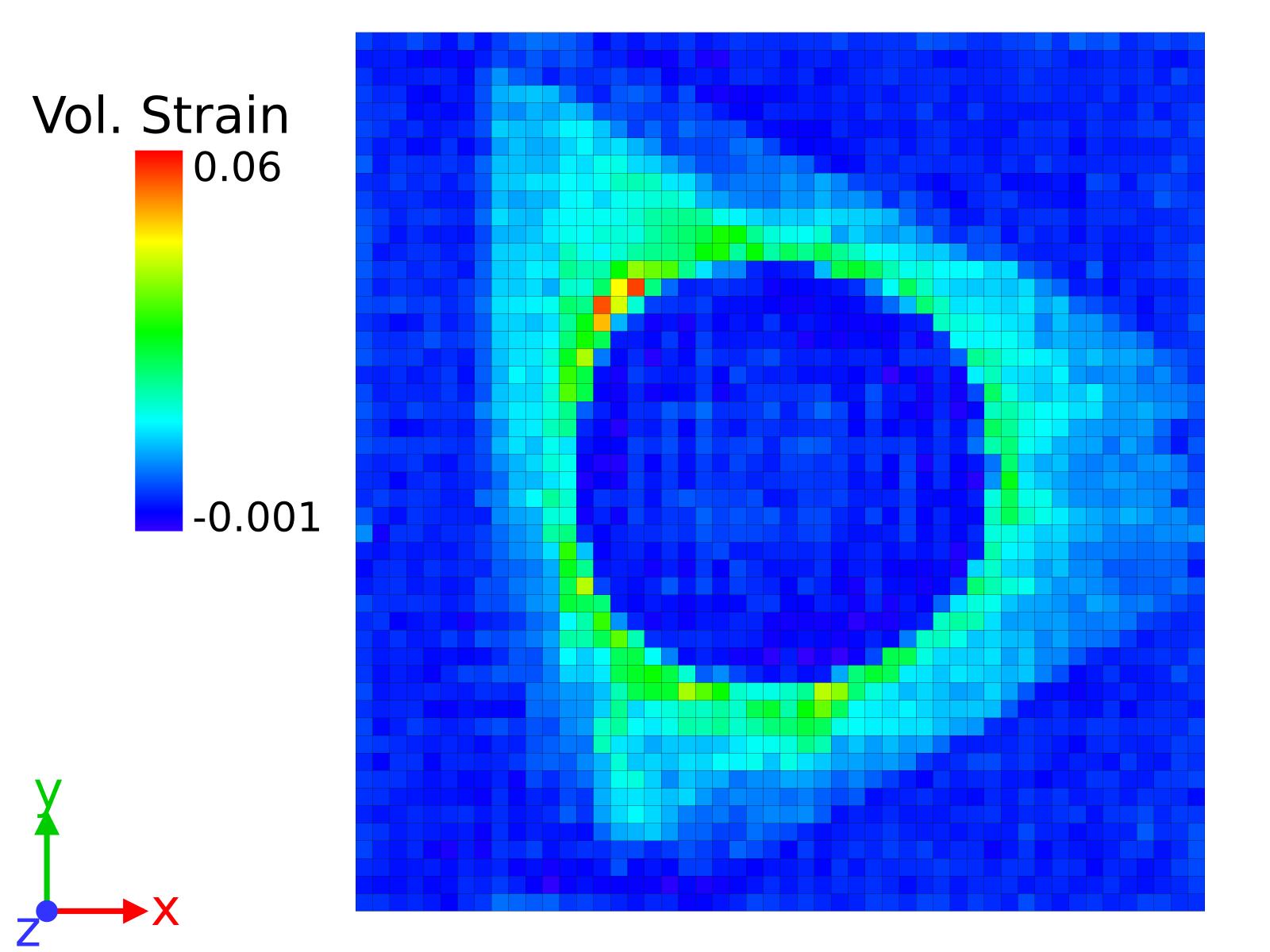
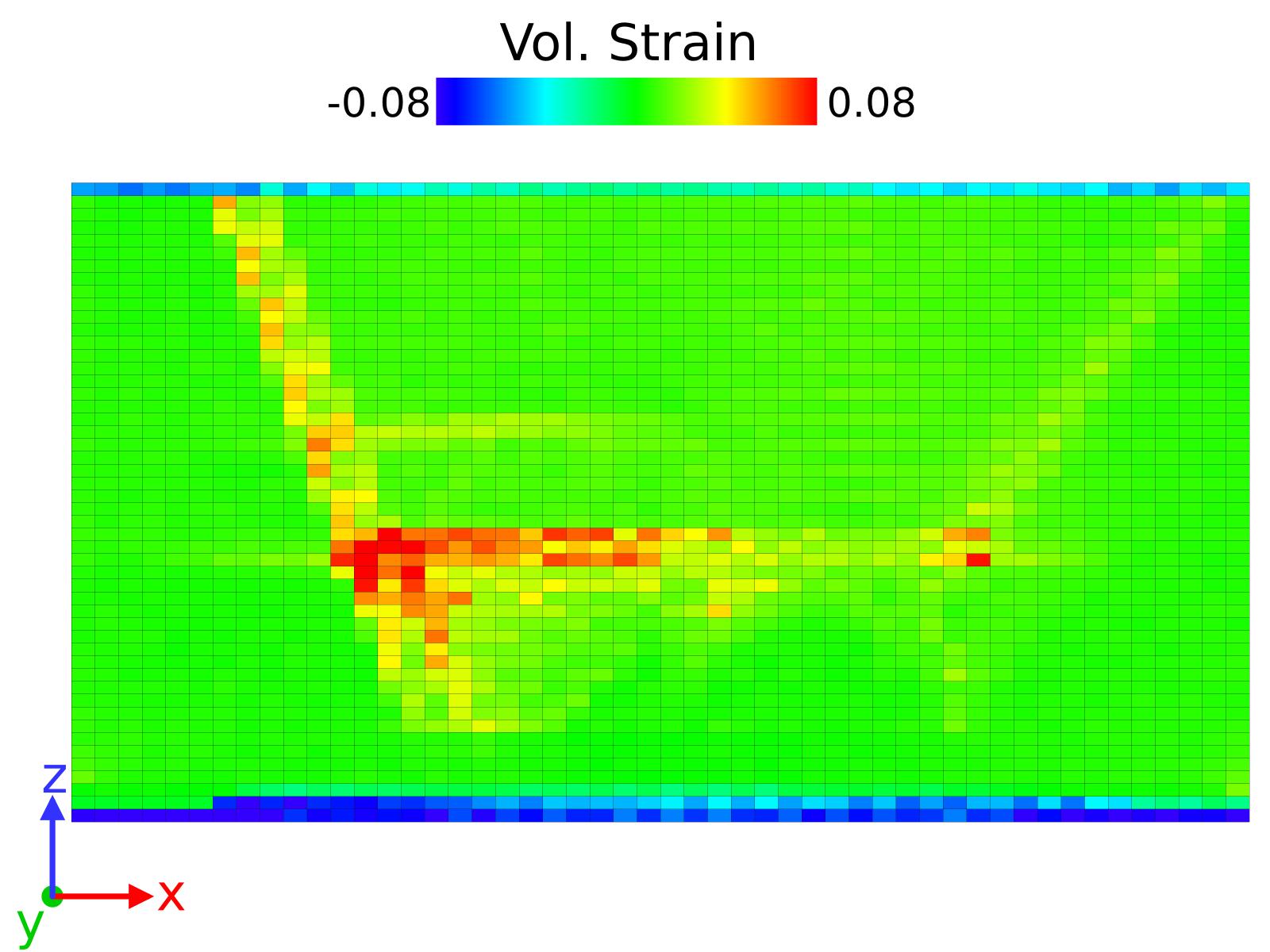
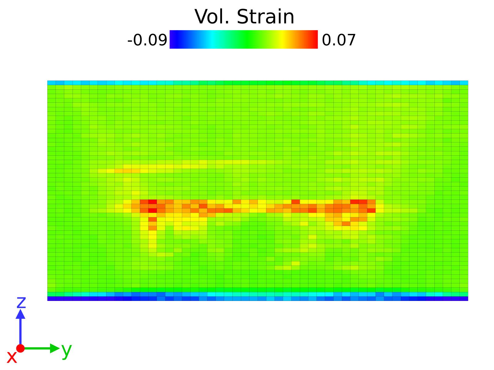
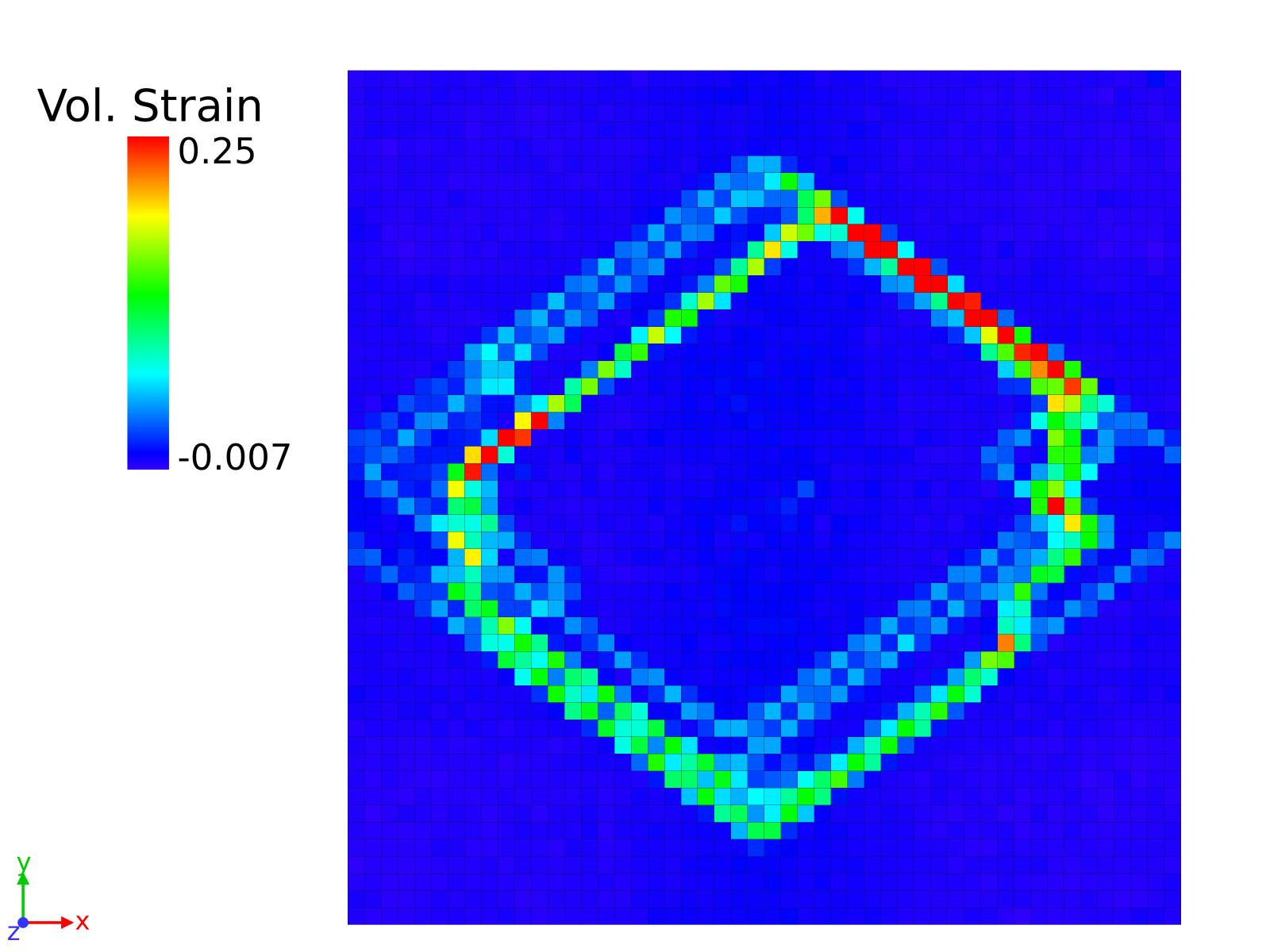
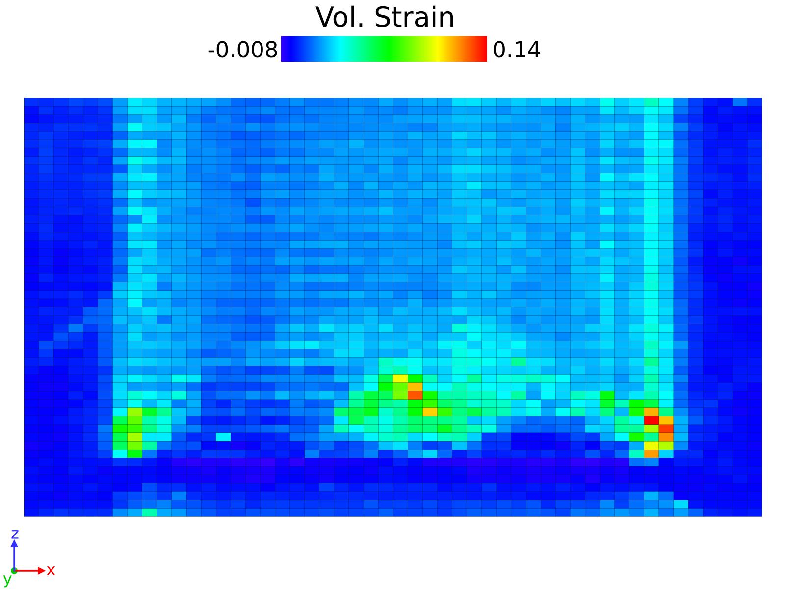
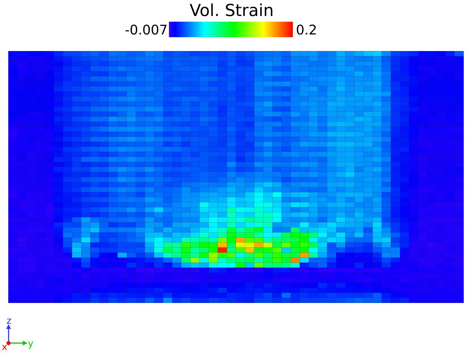
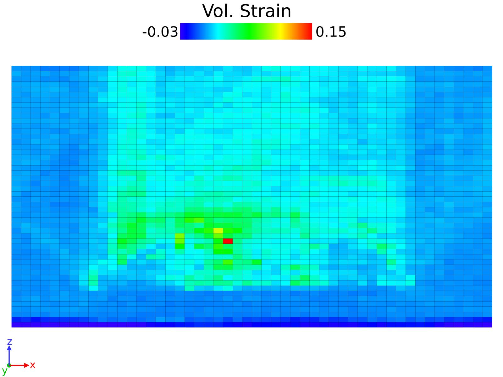
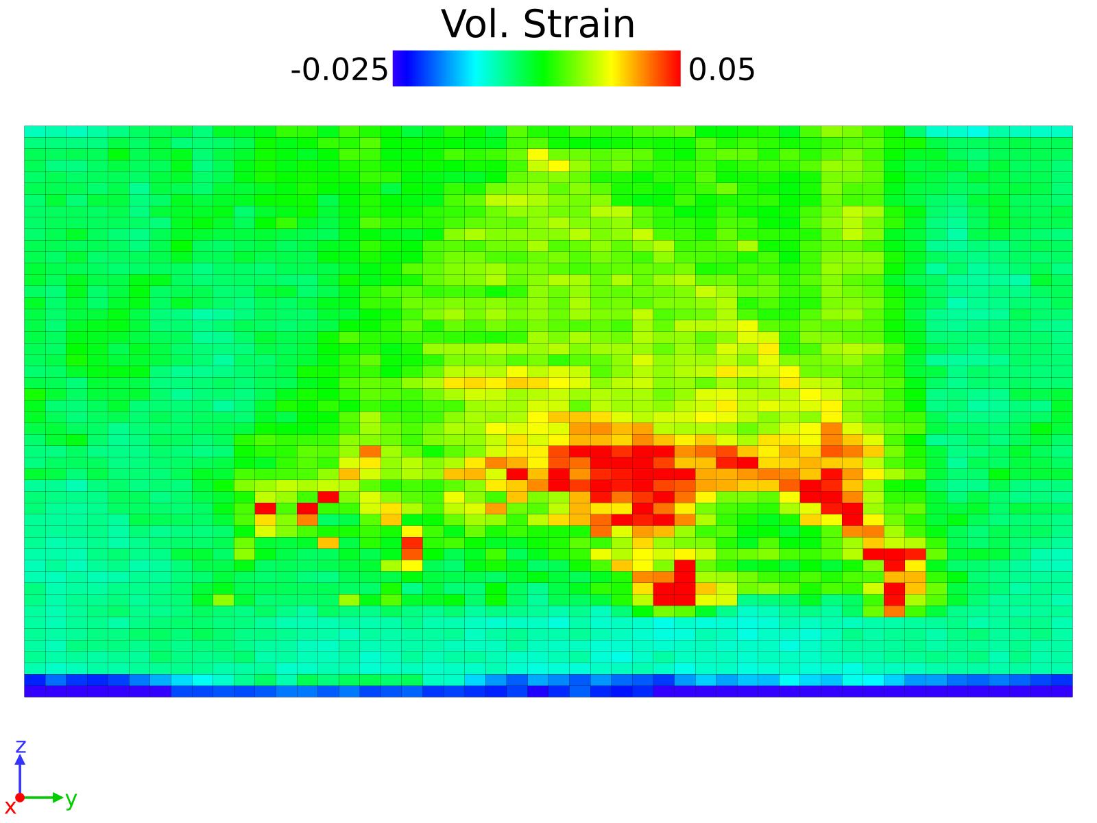
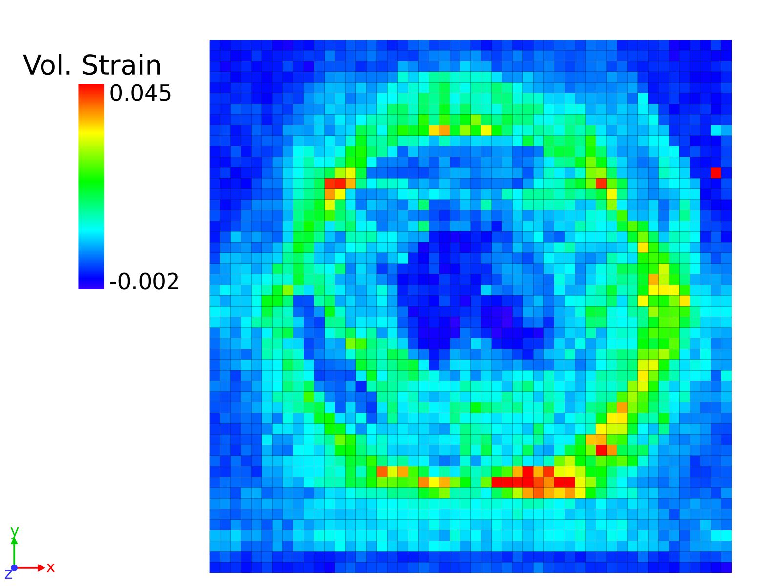
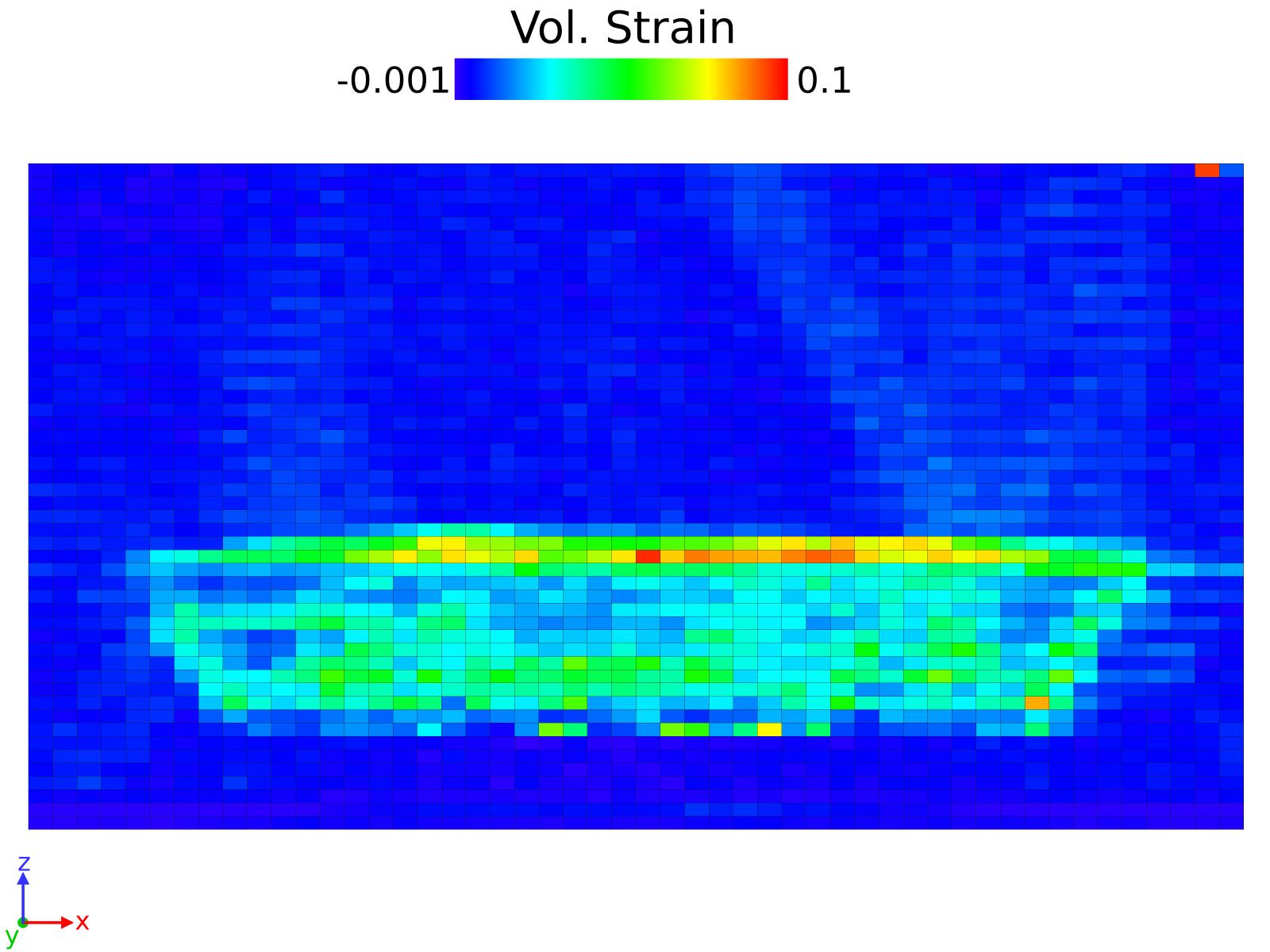
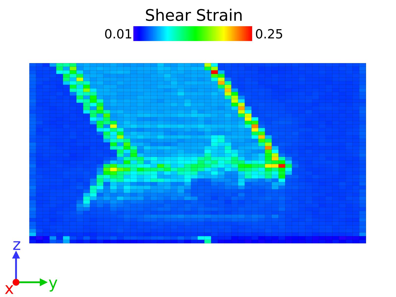
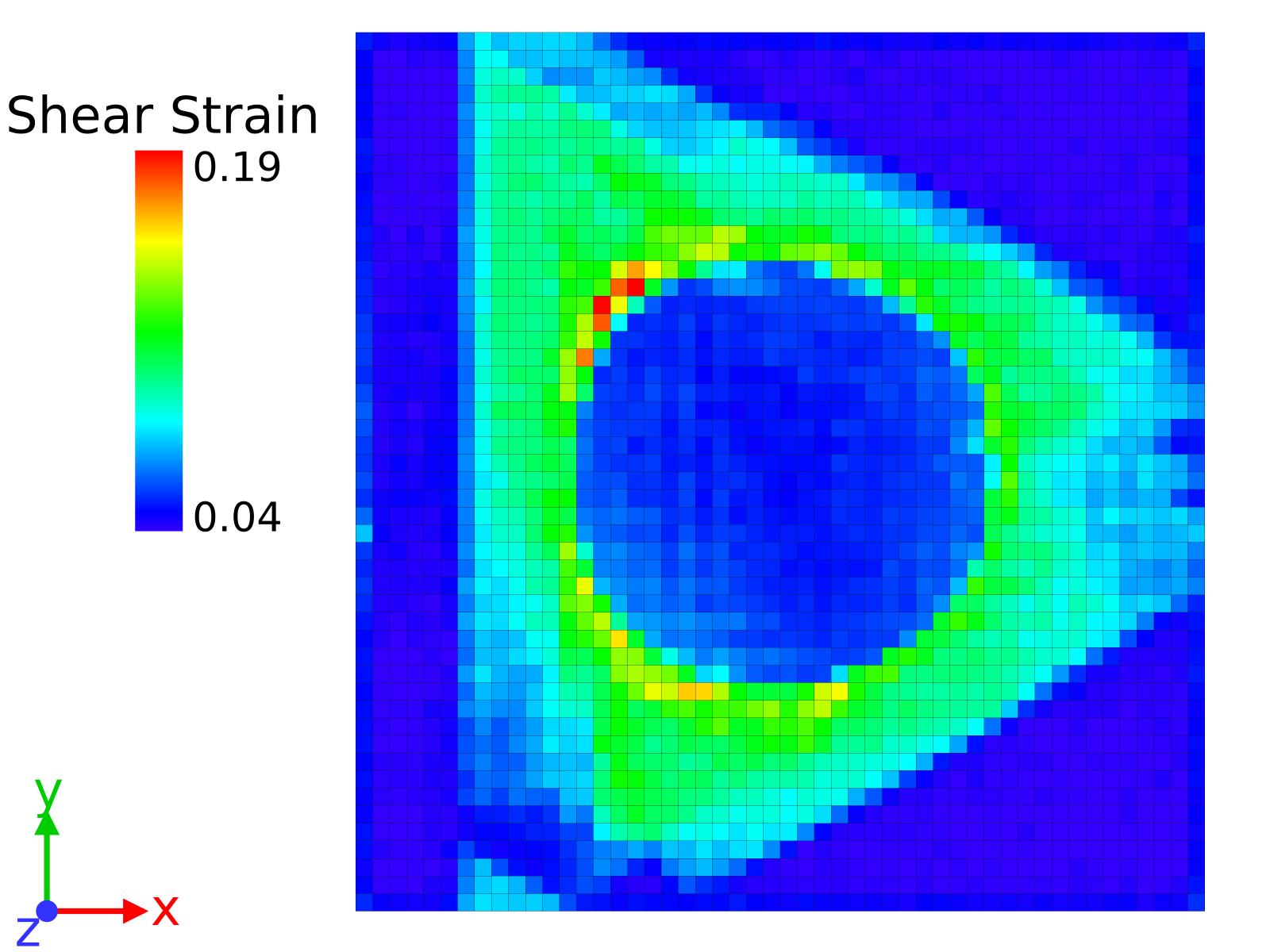
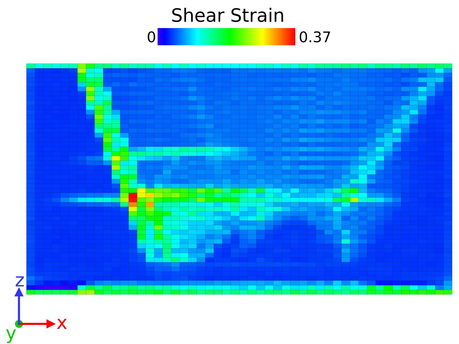
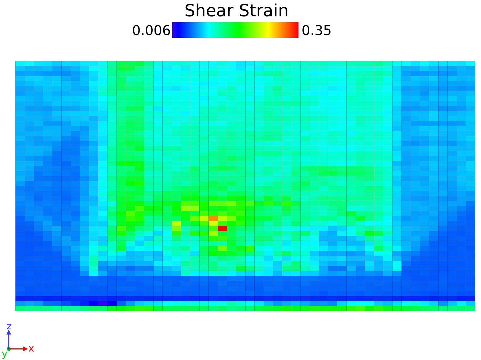
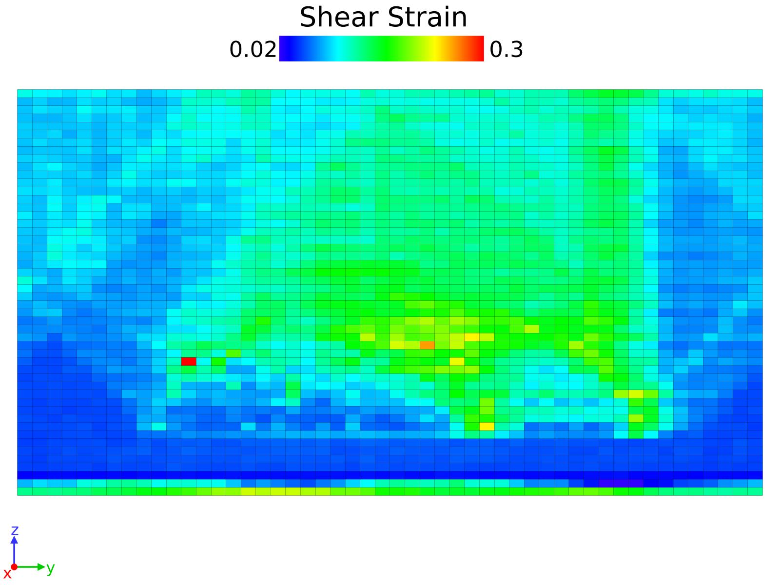
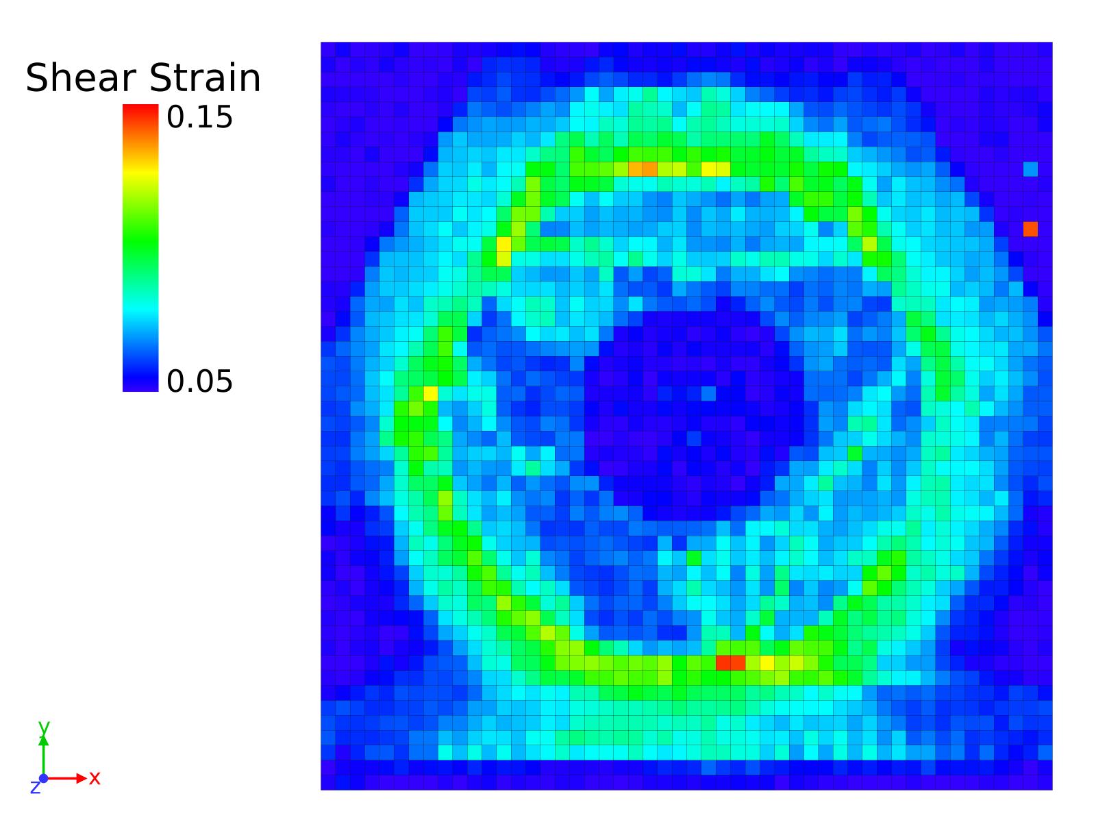
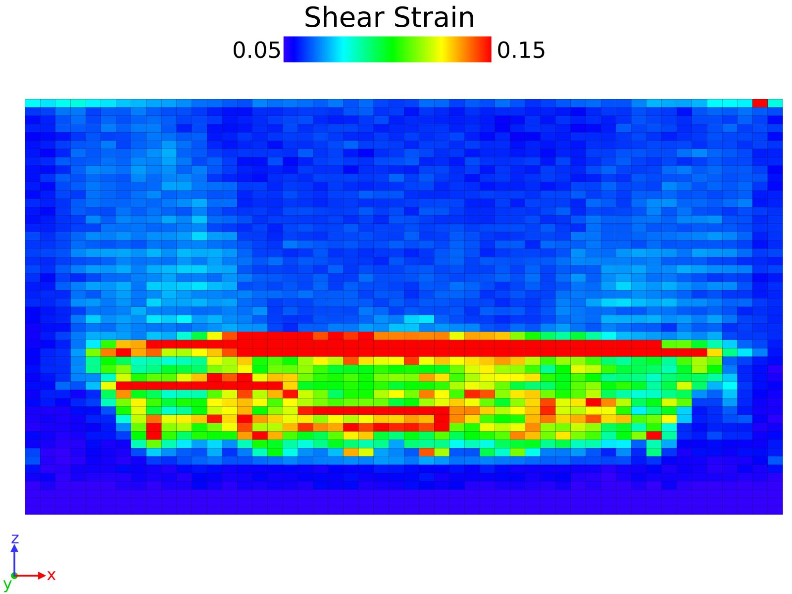
S1.1 Shear Strain analysis
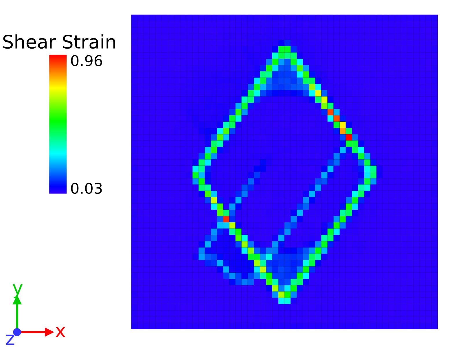
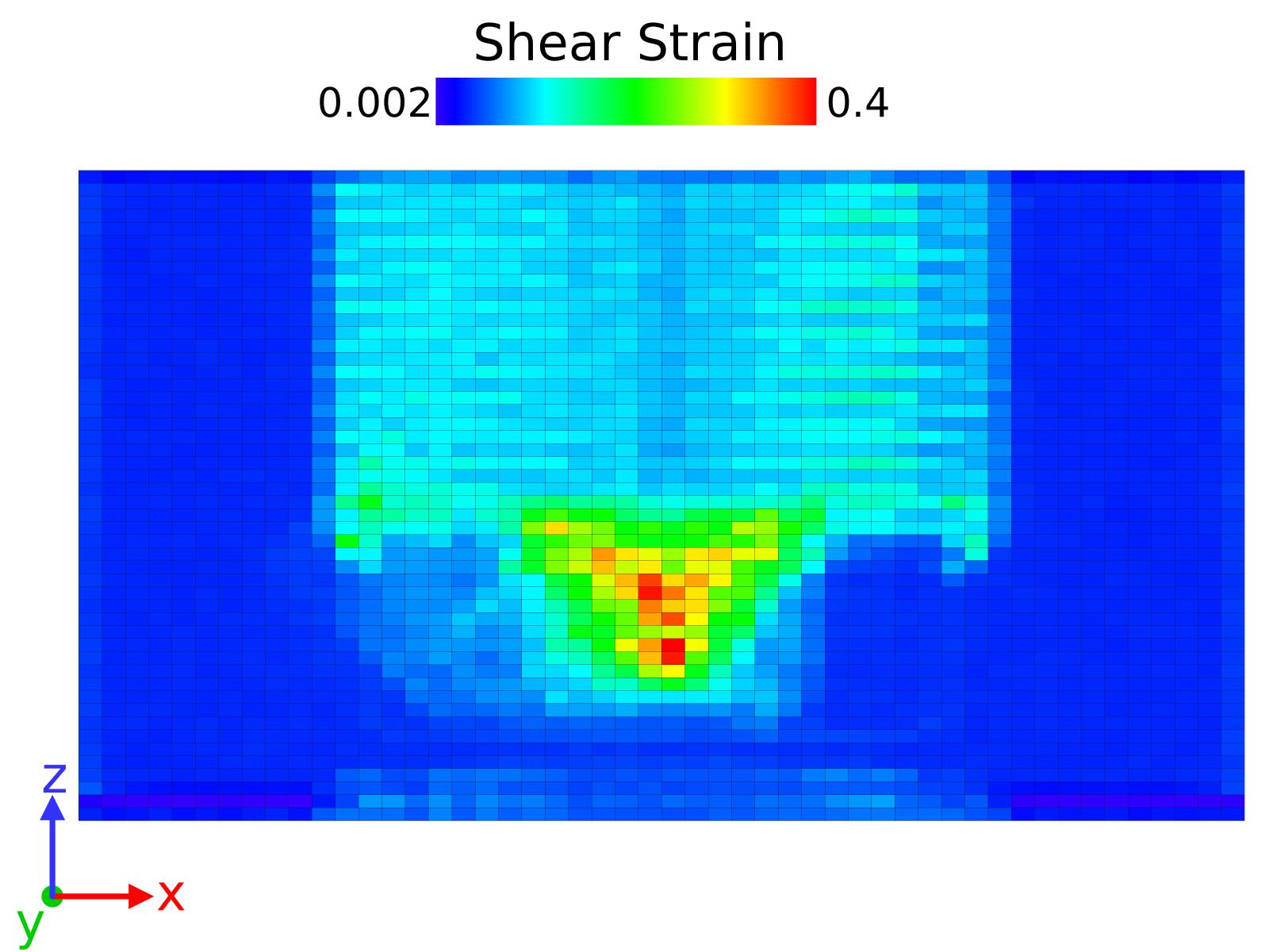
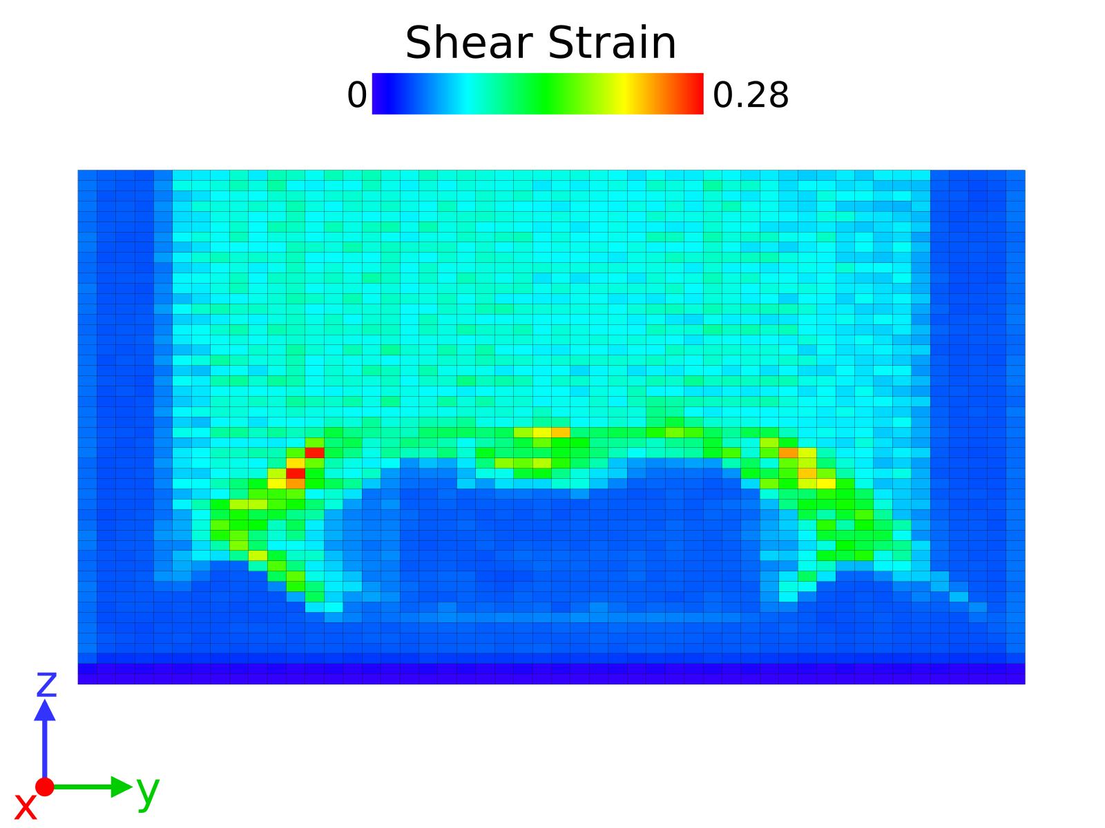
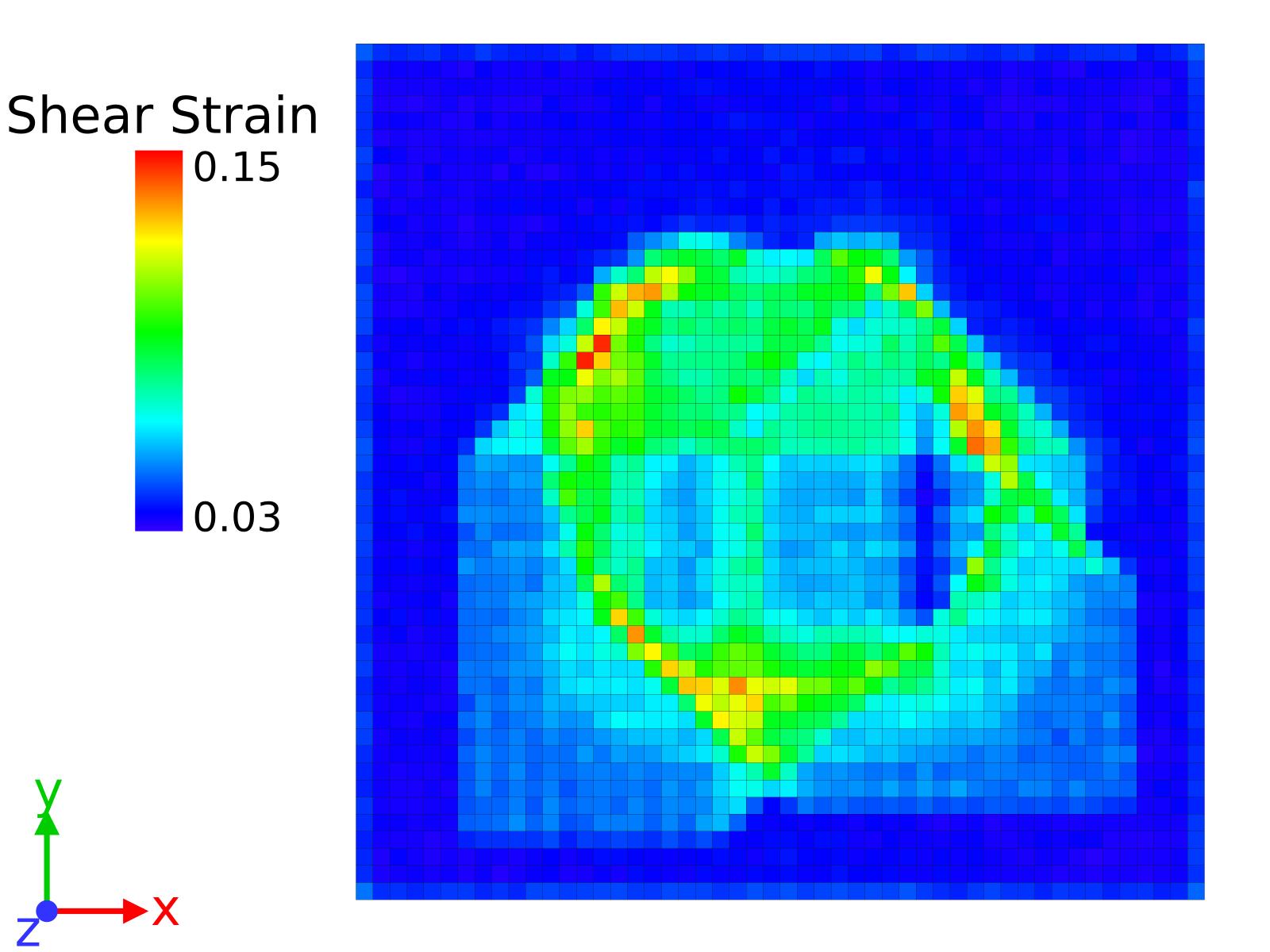
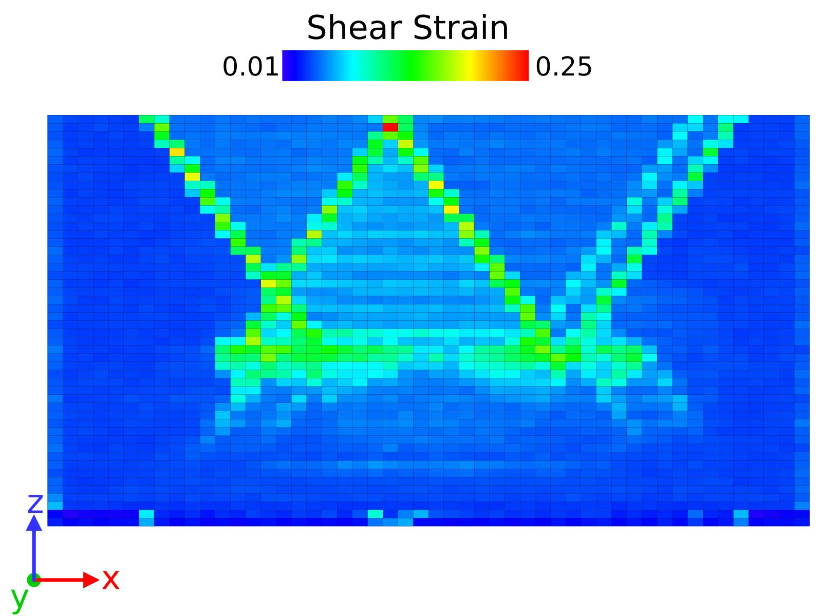
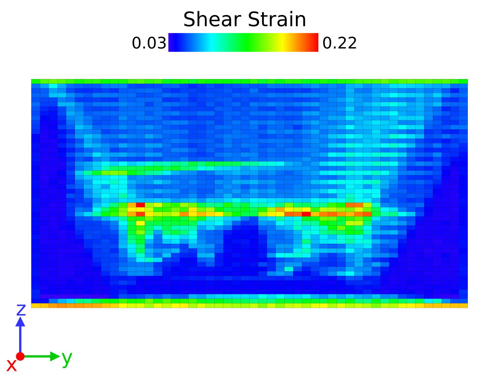
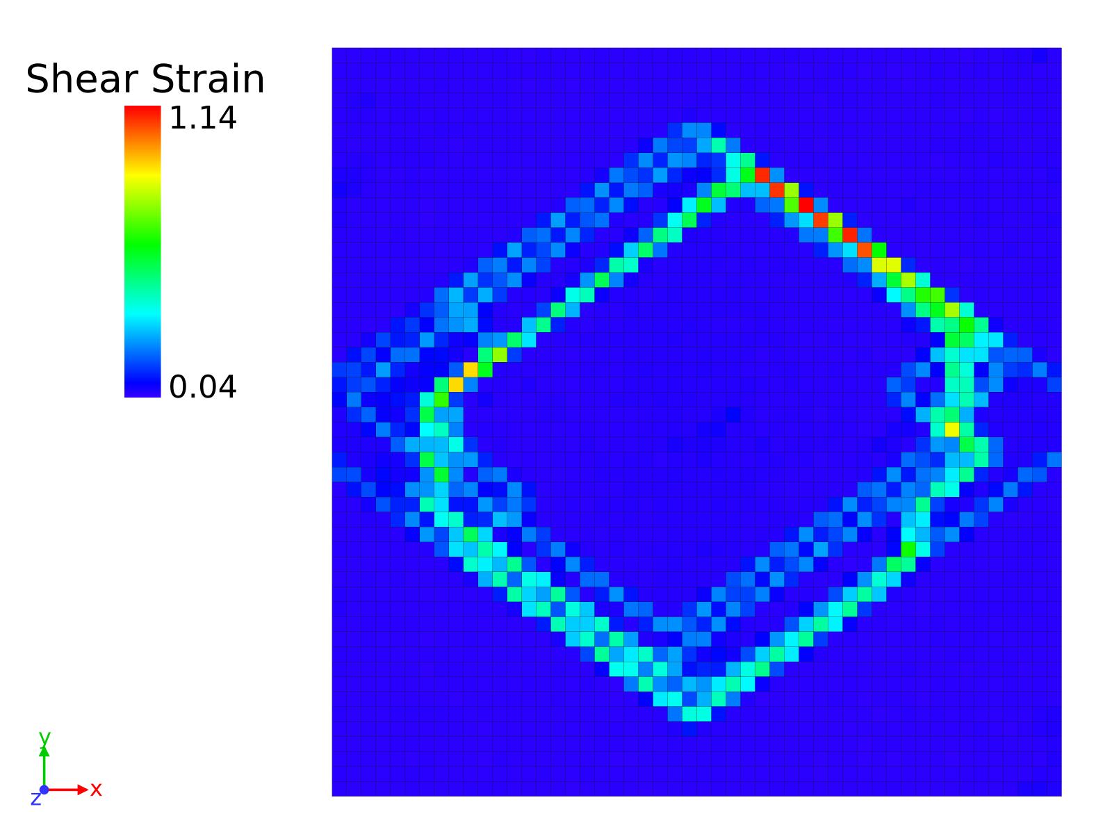
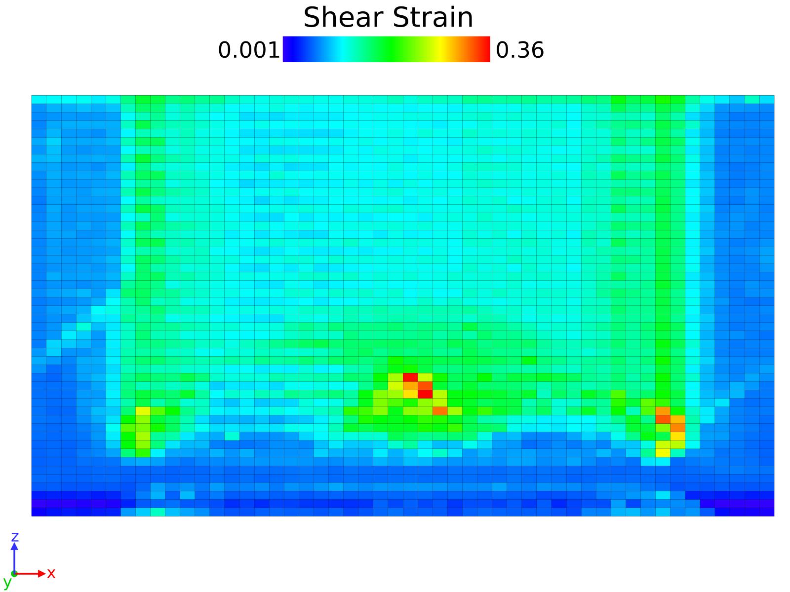
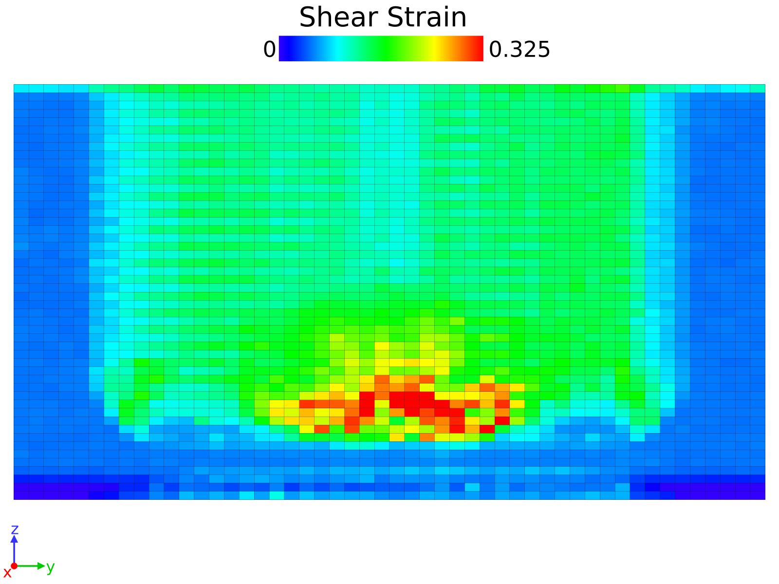

S1.2 Volumetric Strain analysis