DTact: A Vision-Based Tactile Sensor that Measures High-Resolution 3D Geometry Directly from Darkness
Abstract
Vision-based tactile sensors that can measure 3D geometry of the contacting objects are crucial for robots to perform dexterous manipulation tasks. However, the existing sensors are usually complicated to fabricate and delicate to extend. In this work, we novelly take advantage of the reflection property of semitransparent elastomer to design a robust, low-cost, and easy-to-fabricate tactile sensor named DTact. DTact measures high-resolution 3D geometry accurately from the darkness shown in the captured tactile images with only a single image for calibration. In contrast to previous sensors, DTact is robust under various illumination conditions. Then, we build prototypes of DTact that have non-planar contact surfaces with minimal extra efforts and costs. Finally, we perform two intelligent robotic tasks including pose estimation and object recognition using DTact, in which DTact shows large potential in applications.
I Introduction
Tactile perception is essential for robots to sense and interact with the physical world. It enables robots to perceive rich physical information of contact objects [1] such as 3D geometry, force, slip, hardness, and temperature. Among the tactile information, 3D geometry stands out for its ability to infer shapes, poses, textures, and normal forces. Therefore, a tactile sensor that measures 3D geometry accurately and robustly is desired for downstream tasks such as robotic manipulation.
To satisfy the requirement, vision-based tactile sensors such as GelSight are developed to measure high-resolution 3D geometry of the contact objects [2]. Despite the success of these sensors, the core photometric stereo technique [3] has strict requirements for the directions and uniformity of internal illumination. The delicacy significantly increases the complexity of mechanical design and the difficulty of assembly to construct a functional sensor. Besides, such high dependency on illumination strongly hinders extension of GelSight-style sensors into non-planar shapes, which results in many existing sensors [4, 5, 6, 7, 8, 9] having flat surfaces.
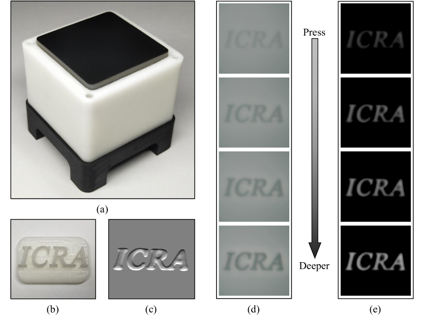
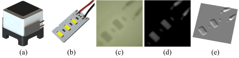
In this work, we creatively leverage the reflection property of the semitransparent elastomer to form a new combination of elastomer layers. With external illumination only, the region of these layers that is pressed deeper would result in a darker color when captured by a camera, as shown in Fig. 1 (d). Employing these layers as the sensing surface, we propose DTact, a robust, low-cost, and easy-to-fabricate tactile sensor that measures high-resolution 3D geometry accurately with a monocular camera. Thanks to the simple yet effective design, DTact only needs a single image for intensity-to-depth calibration; the depth map is directly mapped from the grayscale value. Furthermore, DTact can be easily extended to non-planar sensors because of its low dependency on illumination.
We evaluate the performance of DTact in shape reconstruction from both quantitative and qualitative perspectives. Then we test its robustness under various illumination conditions and explore the effect of elastomer thickness in measuring fine geometry. We also demonstrate its large potential to be extended to sensors with non-planar surfaces. Lastly, we use DTact for two downstream applications: object pose estimation and object recognition.
The rest of this paper is organized as follows. We introduce related work on vision-based tactile sensors for measuring 3D geometry in Section II. We describe the design and fabrication of DTact in Section III. We then present the methods, implementation, and results of shape reconstruction in Section IV. We evaluate DTact’s robustness and potential from different aspects in Section V. Next, we apply DTact to perform two downstream tasks including pose estimation and object recognition in Section VI. Finally, we give the conclusion in Section VII.
II Related Work
Vision-based tactile sensors [2, 10] have become increasingly popular in the robotics community in recent years. GelSight sensor [2] and various revised ones [4, 8, 9, 11] use the photometric stereo technique [3] to measure high-resolution 3D geometry of contact objects with a monocular camera. With a GelSight sensor mounted on the gripper, robots can accomplish challenging tasks such as texture recognition [12, 13, 14], dexterous manipulation [15, 16, 17, 18], shape mapping [19, 20], as well as liquid property estimation [21].
However, photometric stereo technique has strict requirements for the light propagation paths. Specifically, GelSight sensor has to arrange three colors of light (RGB) in different directions to provide internal illumination for a transparent elastomer layer, so that it can use a look-up table to map the changing RGB values to gradients for every pixel. The aforementioned technique brings the sensors high dependency on internal illumination, which further complicates the fabrication process including precise arrangements for LEDs and fine finishing of the silver pigment layer [2]. These problems invoke considerable hurdles to construct a GelSight-like sensor without sufficient expertise, hindering the reproduction of these sensors in the robotics community [22]. Besides, it is hard for these sensors to work under large deformation or measure a slab with zero gradient everywhere.
To resolve these issues, researchers explore the possibilities to build tactile sensors for measuring 3D geometry without using photometric stereo technique. DelTact [23] uses optical flow to estimate the deformation of a dense color pattern, which reduces the dependency on illumination. However, the reconstruction results of DelTact often suffer from the artifacts caused by the estimation algorithms. Moreover, producing the required color patterns is usually time-consuming. Contrastingly, other works directly replace the monocular camera by specialized hardware. Soft-bubble [24] uses a depth sensor to sense the shape of an air-filled membrane, which increases the size and cost of the sensor. GelStereo [25] applies a binocular camera to capture image pairs for sparse surface reconstruction. Improved with self-supervised neural networks [26], GelStereo is able to measure dense 3D geometry at the cost of training neural networks and occasional inaccurate measures. In general, these sensors compromise on certain aspects such as the accuracy, the size, the cost, or the algorithmic complexity to reduce the dependency on illumination. By contrast, DTact measures high-resolution 3D geometry accurately with a monocular camera under simple external illumination. The fabrication, calibration, and reconstruction processes are also improved and simplified in comparison to other sensors.
In real-world robotic tasks, the robots usually require different non-planar shapes of tactile sensor surfaces, to fit either a specialized task, or the mechanical design of their end effector. While some non-planar sensors exist, they may require high fabrication cost [27, 28] or large amounts of data for training the reconstruction models [29, 30]. Unlike previous works, DTact can be extended with a non-planar surface while keeping the illumination condition and reconstruction algorithm the same as planar ones. We attribute these advantages to its robustness against the illumination.
III Design and Fabrication
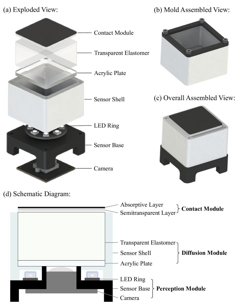
In this section, we aim to elucidate the design and fabrication process of the DTact tactile sensor. We propose a new combination of elastomer layers which directly maps the depth of the elastomer to the intensity of an image. The main components as well as the mold are existing commodities or manufactured by 3D printing as shown in Fig. 2 (a). In contrast to previous holistic sensors such as [31], DTact is modularized based on their structures and functions (as shown in Fig. 2 (d)): the perception module, the diffusion module, and the contact module. As for fabrication, it takes four steps to build the sensor (as shown in Fig. 3). Detailed descriptions about the modules and fabrication are presented as follows.
The perception module. The perception module consists of a sensor base, a camera, and a LED ring. The 3D-printed sensor base supports the whole sensor. We choose a USB camera with a high FOV of degrees. The camera captures image frames with a resolution of at FPS. DTact advocates the USB-based camera port to support multiple platforms, rather than using a Raspberry Pi camera as in previous works [5, 8, 9, 27]. As for illumination, we use an off-the-shelf commercial LED ring (WS2812B-8) to provide stable white light.
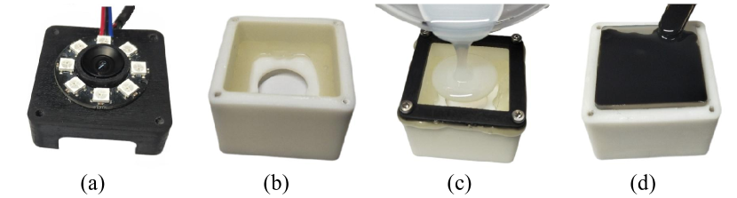
The camera is fastened to the sensor base with M2 screws, while the LED ring is nested in the center of the sensor base, as shown in Fig. 3 (a).
The diffusion module. The diffusion module includes a sensor shell, an acrylic plate, and a block of transparent elastomer. The sensor shell is 3D-printed with white resin and serves as the container for the transparent elastomer. Cut by laser, the 3-mm thick acrylic plate provides a clear window for the camera and supports the transparent elastomer. In order to avoid over-reflection from the LEDs, the transparent elastomer diffuses the light. Specifically, we use stiff transparent silicone (ELASTOSIL® RT 601, 9:1 ratio, shore hardness 45A) as the material of the transparent elastomer.
We first fix the acrylic plate to the sensor shell with hot-melt adhesive, as shown in Fig. 3 (b). Next, we remove the air bubbles in the mixed transparent silicone with a vacuum pump. Finally, we pour it directly into the sensor shell. It takes about 24 hours for the silicone to cure at room temperature.
The contact module. The contact module is made up of a semitransparent layer and an absorptive layer. The soft semitransparent silicone (POSILICONE® , 1:1 ratio, shore hardness 5A which resembles that of human skin) is used to make the semitransparent layer whose brightness changes when deformation occurs. The thickness of the semitransparent layer is . We then make an absorptive layer by mixing the same silicone with black silicone pigment. This layer absorbs the LED light going through the semitransparent layer, so that the tactile images only depends on the light reflected by the semitransparent layer. In addition, the absorptive layer also blocks light from outside environment. The areas that are pressed would become thinner than before. With the combination of the semitransparent layer and the absorptive layer, less light would be reflected by the semitransparent layer; the light going through it would be absorbed by the absorptive layer. Consequently, the contact areas become darker than before. This forms the basic principle of DTact: the deeper an area is pressed, the darker it results in the output.
As shown in Fig. 2 (b), we improve the production process of the contact module [31] by locking an 3D-printed open mold on the sensor shell, into which the defoamed semitransparent silicone is poured directly (Fig. 3 (c)). This improvement can avoid dust and air bubbles between the semitransparent layer and the diffusion elastomer because the semitransparent layer never moves. After the semitransparent silicone cures, we use a stick to paint the defoamed black silicone on the surface of the semitransparent layer, as shown in Fig. 3 (d).
Fig. 2 (c) shows the result of assembling three modules together. The size of the sensor is , which can be easily reduced by using smaller cameras and LED rings if downstream applications (e.g., robotic manipulation) demand. The components of the sensor and the mold cost less than $7 in total without the camera. The fabrication and assembly steps can be reproduced following the illustrated steps.
IV 3D Shape Reconstruction
In this section, we introduce the methods and implementation details of the core function of DTact: 3D shape reconstruction. We propose two possible methods for shape reconstruction in Section IV-A and show the corresponding calibration results in Section IV-B. Then we describe the implementation details of reconstruction in Section IV-C. Finally, we evaluate these methods and examine the visual reconstruction results of representative objects in Section IV-D.
IV-A Reconstruction Methods
We aim to compute the 3D geometry from the pixel intensity of the captured images. Specifically, we need to calculate the pressed depth from the intensity variation value for every pixel, where is the location of a pixel in the image and is the corresponding location on the sensing surface.
The ideal method to reconstruct the pressed depth is to build a look-up table that takes as inputs the intensity variation value and the pixel’s position :
| (1) |
However, it requires a high-precision computer numerical control (CNC) machine to build the high dimensional look-up table, because precise continuous depth for every pixel is needed. This calibration procedure is usually time-consuming and tool-dependent. To simplify the calibration procedure, we propose the following two reconstruction methods in which parameters can be obtained without using a CNC machine.
The single image method. We simplify the look-up table in Equation (1) into a mapping list , which only takes the intensity variation value as input. For all pixels in the image, the pressed depth can be sought from the mapping list:
| (2) |
The linear regression method. In order to take the illumination uniformity into account, we fit a linear mapping function for each pixel. Hence, each pixel would have a specific slope :
| (3) |
Besides, the reference images captured by DTact are slightly brighter in center owing to the circular distribution of the eight LEDs. Therefore, we fit another linear mapping function between the distance to center and the slope :
| (4) |
where is the center of the image.
IV-B Calibration
In this section, we aim to calibrate DTact to solve the parameters used for reconstruction, including in the single image method, and in the linear regression method. We press a metal ball on the DTact and record the images. Knowing the radius of the pressed ball and the corresponding surface size of a pixel, we compute the actual depth maps for the collected images with circle detection algorithms in OpenCV [32]. Therefore, we can infer the parameters from the pressed depth in the actual depth maps and their corresponding pixel intensity variation value .
There are four channels of the pixel intensities can be used to represent , including the RGB and grayscale channels. According to the empirical results of the noise levels of the four channels in the reference images, the grayscale channel has the most stable pixel intensity. Therefore, we choose grayscale channel for calibration and future downstream tasks.
We calibrate the mapping list (shown in Fig. 4 (a)) with only a single image because the ball has continuous geometry from center to edge. For the linear regression method, multiple images are required for fitting. Fig. 4 (b) shows the distribution of the collected points and the fitted regression line. The details about the collected images used to calibrate the parameters for two reconstruction methods are shown in Table I. And we average images within a small time window to obtain stable and accurate calibration.
| Calibration | Reconstruction | ||
|---|---|---|---|
| Single image | Linear regression | ||
| Image amount | 1 | 30 | 20 |
| Ball radius | 4.0 | 4.0 | 5.0 |
| Pressed place | Near center | Randomly | Randomly |

IV-C Implementation Details of Reconstruction
In this section, we reconstruct the 3D geometry of the contact objects using the calibrated parameters. The captured images are first rectified with intrinsic and distortion coefficients to alleviate distortion. Next, we crop the image from pixels to pixels, aligning with the sensing field of .
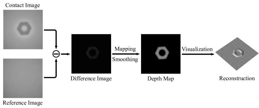
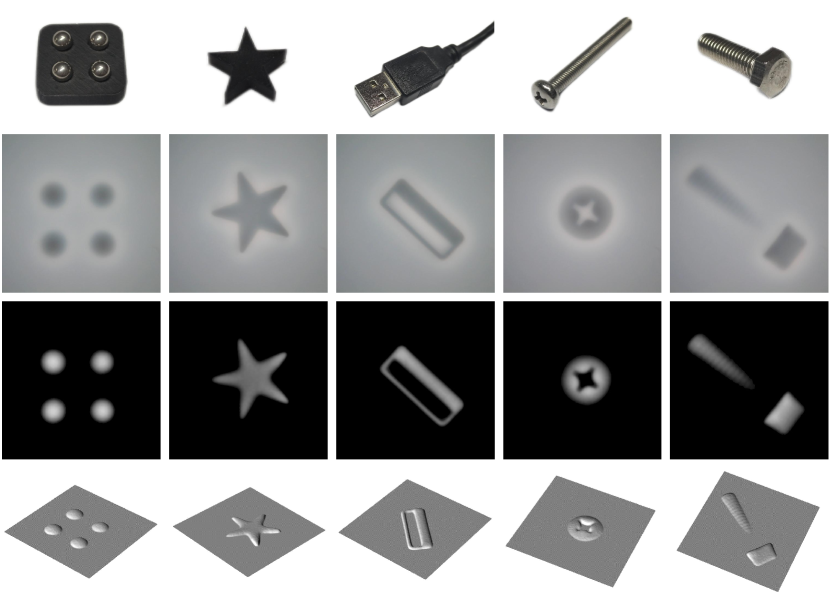
Fig. 5 shows the pipeline to reconstruct 3D geometry of the contact objects. Firstly, we convert the contact image and reference image to the grayscale images. Then, we calculate the difference image by subtracting the reference image from the contact image. After that, the grayscale variation value is mapped to pressed depth for all pixels using the mapping list or regression parameters and . We additionally apply two continuous Gaussian filters both with kernel size to denoise the depth map. Finally, we convert the depth map to a point cloud to render and visualize the reconstructed objects.
The reconstruction algorithm is implemented with Python OpenCV [32] and Open3D [33] libraries. The algorithms for both two reconstruction methods are run on a desktop (Intel Core i7-8550U @1.80GHz) at about 20Hz without using a GPU. In practice, the rectifying, mapping, and smoothing processes take 8ms, 3ms, and 14ms respectively, while the visualization process takes up most of the time. In other words, we can get the final depth map from the raw captured image in 25ms, which is efficient for the downstream robotic tasks.
IV-D Reconstruction Results
In order to quantitatively evaluate the reconstruction quality of the two methods, we press another metal ball of a different size to collect reconstruction test images. The details are summarized in the right-most column of Table I. We compute the generated depth maps using the two reconstruction methods respectively and the actual depth maps by the same algorithms introduced in Section IV-B. Then we calculate the mean absolute error (MAE) between the generated depth maps and corresponding actual depth maps.
The test result in the standard setting is shown in Table II. This result indicates that the single image method outperforms the linear regression method in the test images. There are two main reasons for the test results. On the one hand, DTact diffuses light so that the reference image is with standard deviation (std) as low as 4. This strongly improves the applicability to use the mapping list for all pixels. On the other hand, the errors from the fitting processes introduces additional errors for reconstruction. Therefore, the single image shape reconstruction method is chosen for DTact.
Fig. 6 shows the qualitative reconstruction results of some objects: a ball array, a 3D-printed star, a USB cable head, a screw cap and a M5 hexagonal screw. The reconstructed results are well aligned with the visual appearance of the objects.
V Experiments
In this section, we conduct experiments and aim to answer the following questions: 1) Is DTact robust to various illumination conditions? 2) Can DTact capture fine geometry of contact objects? 3) Can DTact be extended to new sensors with non-planar contact surfaces?
| Standard | Scheme 1 | Scheme 2 | Scheme 3 | Scheme 4 | |
| Std of image | 4.080 | 5.237 | 5.262 | 5.451 | 16.550 |
| Reference image | |||||
| Single image | 0.0476 | 0.0509 | 0.0524 | 0.0650 | 0.0510 |
| Linear regression | 0.0534 | 0.0542 | 0.0586 | 0.0678 | 0.0651 |
V-A Robustness to Illumination Conditions
Low dependency on illumination is the key advantage of DTact. In this section, we change the illumination conditions in both uniformity and direction to evaluate whether DTact is robust to illumination.
Illumination uniformity. The LED ring used for DTact has eight LEDs distributing evenly around a circle. As shown in Table II, we select four of them to form four new configurations, and repeat the processes of calibrations and reconstructions on test images for each of the new configurations. Specifically, for the linear regression method under the fourth configuration, we change the reference position in Equation (4) from center to the upper right corner, because the reference image tends to darken from this corner to the bottom left.
As Table II shows, reconstruction with the single image method has the lowest MAE on test images under all LED configurations including the illumination that is relatively uneven (e.g., the fourth configuration). This demonstrates that compared with the linear regression method that brings errors in fitting processes, the single image method has higher applicability in various illumination conditions. Besides, the MAE values of the single image method only increase slightly under all new LED configurations, which shows DTact’s robustness to illumination uniformity.
Illumination direction. There are two main illumination configurations for most vision-based tactile sensors: lighting from the bottom [31] or from the sides [22]. In this section, we test DTact with LEDs on the sides as Fig. 7 (a) shows. As shown in Fig. 7 (b), We use the same type of LED as for illumination to press on DTact’s surface. With the same pipeline, Fig. 7 (c), (d), and (e) show the tactile image, the depth map and the reconstructed shapes of the object respectively. These qualitative results show that DTact maintains its reconstruction capability with the LEDs on the sides.
V-B Measuring Fine Geometry with Different Layer Thickness
To measure geometry with different fineness, we make semitransparent layers with different thicknesses, namely , , , , and . Three different sizes of set screws are pressed to the sensors with these different layers. The depth maps shown in Fig. 8 indicate that sensors with thinner layers can capture finer geometry. However, the measure range of depth is bounded by the depth of a layer. Therefore, there is a trade-off between fineness and depth in measuring geometry. Applications on different scenarios could choose suitable layer thickness according to their measuring demands.

V-C Non-planar Surface
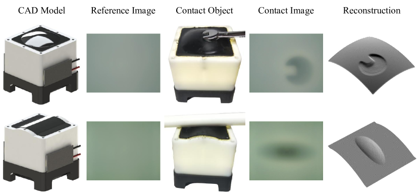
In this section, we extend DTact’s surface to non-planar ones. We reshape the planar surface of DTact into two non-planar surfaces: sphere and cylinder (shown in Fig. 9). Without changing the other parts, the reference images show that the illumination is still uniform with the help of the diffusion module. Therefore, the method to compute depth maps can be re-used for the sensors with non-planar surfaces. Both of the two sensors achieve to reconstruct their surfaces by projecting the depth maps to the non-planar surfaces with ray casting algorithm [29]. The examples indicate that DTact can perform reconstruction even when the surface is non-planar, which usually require complex mechanical design or intricate reconstruction algorithms for other sensors.
VI Applications
In this section, we investigate how DTact can be used for pose estimation and object recognition. This also shows the potential of DTact for robotic applications.
VI-A Pose Estimation
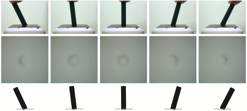
We apply Iterative Closest Point (ICP) [34] on the reconstructed 3D point cloud for pose estimation. Fig. 10 shows an example of tracking the pose of a long M3 nut that rotates from the left around the back to the right. The predicted poses are consistent with the actual poses. In practice, the ICP algorithm from Open3D [33] runs at about 10 Hz on the same desktop introduced in Section IV-C.
VI-B Object Recognition
Object Recognition is important for downstream tasks such as distinguishing different types of machine components in a robot-based factory. We now introduce the datasets, the model, the training details, and the recognition performance.
Dataset. We collect a total of 4,320 tactile images of objects within 12 different categories including metal balls, cylinders, nuts, bolts, spanners, legos of size 1x2 and 2x3, USB-mini cable heads, USB-C cable heads, keys, hex keys, and mesh pen holders. For all the objects, different pressures are applied to create images of different depths.
Architecture and training. We use ResNet-18 [35] as the architecture of our model. The dataset is randomly splitted to 70% being training set and 30% being test set, whereas a 4-fold cross validation is placed on the training set. We use cross-entropy loss and Adam optimizer with a learning rate scheduler, starting from 1e-3 and decaying by every 5 epoches. During training, we perform data augmentations including random crop, random flip, and random rotate.
Results. After 15 epoches, the resnet-18 model achieves 96% accuracy on the test set. This demonstrates that our DTact sensor can capture important features for classifying different objects.
VII Conclusion
We propose DTact, a robust, low-cost, and easy-to-fabricate tactile sensor that measures high-resolution 3D geometry accurately. The core contribution of DTact is that it maintains tactile sensing performance while relieving a prevalent issue in previous sensors: heavy dependency on illumination. Experiments show that DTact not only measures geometry accurately under various illumination conditions, but also captures details of object with fine geometry. More importantly, DTact can be easily extended with non-planar surfaces, achieving reconstruction efficiently. Finally, DTact can be used for downstream tasks such as pose estimation and object recognition, exhibiting its potential to be used in real world scenarios.
References
- [1] A. C. Abad and A. Ranasinghe, “Visuotactile sensors with emphasis on gelsight sensor: A review,” IEEE Sensors Journal, vol. 20, no. 14, pp. 7628–7638, 2020.
- [2] W. Yuan, S. Dong, and E. H. Adelson, “Gelsight: High-resolution robot tactile sensors for estimating geometry and force,” Sensors, vol. 17, no. 12, p. 2762, 2017.
- [3] M. K. Johnson and E. H. Adelson, “Retrographic sensing for the measurement of surface texture and shape,” in 2009 IEEE Conference on Computer Vision and Pattern Recognition. IEEE, 2009, pp. 1070–1077.
- [4] S. Dong, W. Yuan, and E. H. Adelson, “Improved gelsight tactile sensor for measuring geometry and slip,” in 2017 IEEE/RSJ International Conference on Intelligent Robots and Systems (IROS). IEEE, 2017, pp. 137–144.
- [5] E. Donlon, S. Dong, M. Liu, J. Li, E. Adelson, and A. Rodriguez, “Gelslim: A high-resolution, compact, robust, and calibrated tactile-sensing finger,” in 2018 IEEE/RSJ International Conference on Intelligent Robots and Systems (IROS). IEEE, 2018, pp. 1927–1934.
- [6] D. Ma, E. Donlon, S. Dong, and A. Rodriguez, “Dense tactile force estimation using gelslim and inverse fem,” in 2019 International Conference on Robotics and Automation (ICRA). IEEE, 2019, pp. 5418–5424.
- [7] M. Lambeta, P.-W. Chou, S. Tian, B. Yang, B. Maloon, V. R. Most, D. Stroud, R. Santos, A. Byagowi, G. Kammerer, et al., “Digit: A novel design for a low-cost compact high-resolution tactile sensor with application to in-hand manipulation,” IEEE Robotics and Automation Letters, vol. 5, no. 3, pp. 3838–3845, 2020.
- [8] S. Wang, Y. She, B. Romero, and E. Adelson, “Gelsight wedge: Measuring high-resolution 3d contact geometry with a compact robot finger,” in 2021 IEEE International Conference on Robotics and Automation (ICRA). IEEE, 2021, pp. 6468–6475.
- [9] I. H. Taylor, S. Dong, and A. Rodriguez, “Gelslim 3.0: High-resolution measurement of shape, force and slip in a compact tactile-sensing finger,” in 2022 International Conference on Robotics and Automation (ICRA). IEEE, 2022, pp. 10 781–10 787.
- [10] B. Ward-Cherrier, N. Pestell, L. Cramphorn, B. Winstone, M. E. Giannaccini, J. Rossiter, and N. F. Lepora, “The tactip family: Soft optical tactile sensors with 3d-printed biomimetic morphologies,” Soft robotics, vol. 5, no. 2, pp. 216–227, 2018.
- [11] N. F. Lepora, Y. Lin, B. Money-Coomes, and J. Lloyd, “Digitac: A digit-tactip hybrid tactile sensor for comparing low-cost high-resolution robot touch,” IEEE Robotics and Automation Letters, vol. 7, no. 4, pp. 9382–9388, 2022.
- [12] R. Li and E. H. Adelson, “Sensing and recognizing surface textures using a gelsight sensor,” in Proceedings of the IEEE Conference on Computer Vision and Pattern Recognition, 2013, pp. 1241–1247.
- [13] S. Luo, W. Yuan, E. Adelson, A. G. Cohn, and R. Fuentes, “Vitac: Feature sharing between vision and tactile sensing for cloth texture recognition,” in 2018 IEEE International Conference on Robotics and Automation (ICRA). IEEE, 2018, pp. 2722–2727.
- [14] W. Yuan, Y. Mo, S. Wang, and E. H. Adelson, “Active clothing material perception using tactile sensing and deep learning,” in 2018 IEEE International Conference on Robotics and Automation (ICRA). IEEE, 2018, pp. 4842–4849.
- [15] S. Tian, F. Ebert, D. Jayaraman, M. Mudigonda, C. Finn, R. Calandra, and S. Levine, “Manipulation by feel: Touch-based control with deep predictive models,” in 2019 International Conference on Robotics and Automation (ICRA). IEEE, 2019, pp. 818–824.
- [16] C. Wang, S. Wang, B. Romero, F. Veiga, and E. Adelson, “Swingbot: Learning physical features from in-hand tactile exploration for dynamic swing-up manipulation,” in 2020 IEEE/RSJ International Conference on Intelligent Robots and Systems (IROS). IEEE, 2020, pp. 5633–5640.
- [17] Y. She, S. Wang, S. Dong, N. Sunil, A. Rodriguez, and E. Adelson, “Cable manipulation with a tactile-reactive gripper,” The International Journal of Robotics Research, vol. 40, no. 12-14, pp. 1385–1401, 2021.
- [18] S. Dong, D. K. Jha, D. Romeres, S. Kim, D. Nikovski, and A. Rodriguez, “Tactile-rl for insertion: Generalization to objects of unknown geometry,” in 2021 IEEE International Conference on Robotics and Automation (ICRA). IEEE, 2021, pp. 6437–6443.
- [19] M. Bauza, O. Canal, and A. Rodriguez, “Tactile mapping and localization from high-resolution tactile imprints,” in 2019 International Conference on Robotics and Automation (ICRA). IEEE, 2019, pp. 3811–3817.
- [20] S. Suresh, Z. Si, J. G. Mangelson, W. Yuan, and M. Kaess, “Shapemap 3-d: Efficient shape mapping through dense touch and vision,” in 2022 International Conference on Robotics and Automation (ICRA). IEEE, 2022, pp. 7073–7080.
- [21] H.-J. Huang, X. Guo, and W. Yuan, “Understanding dynamic tactile sensing for liquid property estimation,” arXiv preprint arXiv:2205.08771, 2022.
- [22] Y. Du, G. Zhang, Y. Zhang, and M. Y. Wang, “High-resolution 3-dimensional contact deformation tracking for fingervision sensor with dense random color pattern,” IEEE Robotics and Automation Letters, vol. 6, no. 2, pp. 2147–2154, 2021.
- [23] G. Zhang, Y. Du, H. Yu, and M. Y. Wang, “Deltact: A vision-based tactile sensor using dense color pattern,” arXiv preprint arXiv:2202.02179, 2022.
- [24] A. Alspach, K. Hashimoto, N. Kuppuswamy, and R. Tedrake, “Soft-bubble: A highly compliant dense geometry tactile sensor for robot manipulation,” in 2019 2nd IEEE International Conference on Soft Robotics (RoboSoft). IEEE, 2019, pp. 597–604.
- [25] S. Cui, R. Wang, J. Hu, J. Wei, S. Wang, and Z. Lou, “In-hand object localization using a novel high-resolution visuotactile sensor,” IEEE Transactions on Industrial Electronics, vol. 69, no. 6, pp. 6015–6025, 2021.
- [26] S. Cui, R. Wang, J. Hu, C. Zhang, L. Chen, and S. Wang, “Self-supervised contact geometry learning by gelstereo visuotactile sensing,” IEEE Transactions on Instrumentation and Measurement, vol. 71, pp. 1–9, 2021.
- [27] B. Romero, F. Veiga, and E. Adelson, “Soft, round, high resolution tactile fingertip sensors for dexterous robotic manipulation,” in 2020 IEEE International Conference on Robotics and Automation (ICRA). IEEE, 2020, pp. 4796–4802.
- [28] A. Padmanabha, F. Ebert, S. Tian, R. Calandra, C. Finn, and S. Levine, “Omnitact: A multi-directional high-resolution touch sensor,” in 2020 IEEE International Conference on Robotics and Automation (ICRA). IEEE, 2020, pp. 618–624.
- [29] W. K. Do and M. Kennedy, “Densetact: Optical tactile sensor for dense shape reconstruction,” in 2022 International Conference on Robotics and Automation (ICRA). IEEE, 2022, pp. 6188–6194.
- [30] H. Sun, K. J. Kuchenbecker, and G. Martius, “A soft thumb-sized vision-based sensor with accurate all-round force perception,” Nature Machine Intelligence, vol. 4, no. 2, pp. 135–145, 2022.
- [31] C. Sferrazza and R. D’Andrea, “Design, motivation and evaluation of a full-resolution optical tactile sensor,” Sensors, vol. 19, no. 4, p. 928, 2019.
- [32] G. Bradski, “The opencv library.” Dr. Dobb’s Journal: Software Tools for the Professional Programmer, vol. 25, no. 11, pp. 120–123, 2000.
- [33] Q.-Y. Zhou, J. Park, and V. Koltun, “Open3d: A modern library for 3d data processing,” arXiv preprint arXiv:1801.09847, 2018.
- [34] P. J. Besl and N. D. McKay, “Method for registration of 3-d shapes,” in Sensor fusion IV: control paradigms and data structures, vol. 1611. Spie, 1992, pp. 586–606.
- [35] K. He, X. Zhang, S. Ren, and J. Sun, “Deep residual learning for image recognition,” in Proceedings of the IEEE conference on computer vision and pattern recognition, 2016, pp. 770–778.