Super spontaneous four-wave mixing in an array of silicon microresonators
Abstract
Composite optical systems can show compelling collective dynamics. For instance, the cooperative decay of quantum emitters into a common radiation mode can lead to superradiance, where the emission rate of the ensemble is larger than the sum of the rates of the individual emitters. Here, we report experimental evidence of super spontaneous four-wave mixing (super SFWM), an analogous effect for the generation of photon pairs in a parametric nonlinear process on an integrated photonic device. We study this phenomenon in an array of microring resonators on a silicon photonic chip coupled to bus waveguides. We measured a cooperative pair generation rate that always exceeds the incoherent sum of the rates of the individual resonators. We investigate the physical mechanisms underlying this collective behaviour, clarify the impact of loss, and address the aspects of fundamental and technological relevance of our results.
I Introduction
When multiple quantum emitters are coupled to the electromagnetic field, their collective dynamics can fundamentally differ from that of isolated emitters. “Superradiance,” which is the enhancement of the spontaneous emission rate of a collection of such emitters, is a quintessential example of this difference. The pioneering work on superradiance was due to Dicke [1], and since his paper in 1954 the effect has been the subject of a large number of theoretical investigations and experimental demonstrations (see, e.g., [2, 3, 4] and references therein), acquiring technological relevance in the fields of quantum information science [5, 6, 7], laser physics [8] and metrology [9]. Although conceptually simple, its experimental validation is challenged by difficulties in precisely preparing the initial quantum state, and in controlling detrimental interactions with the environment [2, 3]. In experiments involving dilute atomic clouds, this is often achieved by laser cooling in magneto-optical traps [10, 11, 12]. The presence of a large number of atoms only provides a macroscopic description of the behaviour of the system. Yet, with progress in materials science and nanotechnology, it is now possible to initialize a collection of single emitters in the so-called Dicke bright and dark states – i.e., the maximally super- and subradiant states – with high fidelity [5]. Moreover, selective coupling to nanophotonic waveguides or cavities can be engineered to tailor the spontaneous emission into a restricted set of radiation modes [13, 14]. Recent studies have demonstrated cooperative effects between quantum emitters involving a wide variety of platforms, including superconducting qubits [15, 16], quantum dots [17, 18, 19], trapped ions [13], cold atoms [20], and colour centers in diamond [21, 22]. These platforms need to operate in cryogenic environments, for the systems under study are notoriously prone to decoherence.
Superradiance in parametric processes such as four-wave mixing [12] has been subject of several works, mostly focusing on coherent matter-wave amplification [23, 24].
Recently, Onodera et al. [25] have identified a striking resemblance between Dicke superradiance and the enhancement of parametric fluorescence from an ensemble of identical resonators. In their theoretical work, the authors considered spontaneous four-wave mixing (SFWM) in a sequence of lossless microring resonators arranged in an all-pass configuration, and named the process super SFWM. For a quasi continuous-wave (CW) pump, and in the limit of a small probability of generating a photon pair within the pump coherence time, they predicted that the pair generation rate would be characterized by a super-linear scaling with the number of resonators. Superradiance here is associated with the impossibility of knowing in which resonator the photon pair is generated, with the quantum state given by a coherent superposition of the states associated with a pair being generated in each of the resonators. The analogy was drawn completely in the optical domain and on an integrated photonic device, considerably simplifying its experimental realization. Beside the fundamental aspect, the demonstration of super SFWM would acquire technological relevance for the realization of bright sources based on cooperative photon pair emission between resonators. Yet, the theoretical work of Onodera et. al [25] did not consider the effects of propagation losses, unavoidable in any actual implementation. Indeed, in the all-pass geometry considered by the authors, such effect would have progressively decreased the transmittance along the sequence, spoiling very soon the cooperative character of spontaneous emission. Would it be possible to observe super SFWM in the presence of losses? What would it be their impact?
We addressed those questions by experimentally investigating super SFWM in an array of ring resonator photon pair sources [26] integrated on a silicon chip. We exploit the integrated photonic platform to control precisely the state of each emitter, harnessing the reconfigurability of the device to vary the number of collectively excited emitters. We study the scaling of the efficiencies of spontaneous and stimulated FWM [27] for an increasing array size, demonstrating profound differences with respect to the case of an ensemble of independent resonators. This allows us to prove that the array exhibits cooperative emission. The impact of loss and spectral filtering on the pump and on the photon pairs generated are investigated both experimentally and by numerical simulation.
II Device and experimental setup
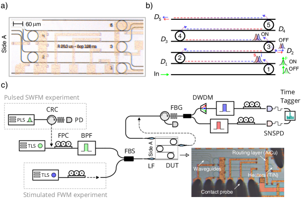
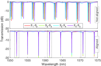
An optical microscope image and a functional scheme of the device are shown in Fig.1(a) and Fig.1(b), respectively. The photonic circuit consists of an array of five ring resonators (emitters) in the add-drop filter configuration [28], where each drop port is used to excite the next emitter in the sequence. We label the drop port of the ring as , as indicated in Fig.1(b). Contrarily to the all-pass scheme proposed in [25], this configuration avoids the drop of the pump power, as well of photon pairs, along the sequence. At the same time, it does not compromise the possibility of coherently exciting all the rings simultaneously. The device is patterned on a Silicon-on-Insulator wafer using standard photolithography (details in the Supplemental Material [29]). The experimental setup is shown in Fig.1(c). The chip is mounted on a sample holder that is temperature stabilized. Metallic micro-heaters allow for the independent tuning of the resonance wavelength of each ring through the thermo-optic effect. The applied electrical current is controlled by two separate multi-contact probes (bottom and top of the inset in Fig.1(c)) which are placed in contact to the chip metallic pads. The probes are connected to five independent current/voltage output channels. The chip is designed to have the drop ports , with odd, on the left-hand side (side A in the inset of Fig.1), while the even ports lie on the right-hand side. Micrometric positioning stages are used to align lensed fibers to the input/output chip waveguides. Two fibers are placed on side A, and are respectively used to inject the pump light and to collect photon pairs from the ports and . The difference of the transmission losses between the fibers that are used to collect photon pairs is about dB. This offset has been applied to calibrate the coincidence rates collected from the even and the odd drop ports. A coupling loss of about dB/facet is achieved using waveguide terminated inverse tapers of width around nm. With the heaters off, we injected light into ports through and probed the transmission spectra of the different rings with a CW tunable laser. These are shown superimposed in the upper panel of Fig.2. The rings possess slightly different resonance wavelengths, showing in the spectra as clustered dips which are separated by multiples of the resonator free spectral range (FSR). By regulating the current in the heaters, the spectra of the rings can be overlapped, which is the condition shown in the lower panel of Fig.2. In this configuration, the pump light, injected at the input and on resonance with all the rings, is dropped multiple times (average loss of dB for each drop event) and coherently excites all the emitters in the array. The path from the input to (dashed line in Fig.1(b)) defines a common channel, shared by all the resonators, and in which it is not possible to discern which emitter fired. We can reconfigure the length of the sequence to by setting the ring out of resonance (OFF state in Fig.1(b)). Signal and idler photons generated by SFWM are collected from two resonances at and , which are separated by two FSR from the pump wavelength . The average quality factors are , and , showing good uniformity among the rings (see Supplemental Material [29] for a comprehensive characterization). The collected pairs undergo a preliminar filtering stage which attenuates ( dB) the pump beam through a Bragg grating and a circulator. Then, they are probabilistically separated using a fiber beam splitter, and the signal/idler paths are defined by the different center wavelengths of two sets of bandpass filters, achieving nearly dB of pump suppression. Their bandwidth is sufficiently large to accommodate two resonance orders within their passband. In order to select the coincidence events originating from only one set of resonances, we placed an additional GHz Dense Wavelength Demultiplexing Module (DWDM) on the idler path. Coincidence measurements are performed using two superconducting detectors and time tagging electronics.
III Results
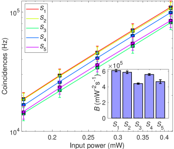
As a first step, we characterized the brightness () of each source to evaluate the uniformity of the array. To test , we coupled the pump laser to port , and tuned the sources into an OFF state. Photon pairs are collected in transmission as a function of the input power. The coincidence rate at the output of the resonator are reported in Fig.3. All the curves show the characteristic quadratic scaling of SFWM with the pump power. The brightness of the emitters is quite uniform, with an average value of .
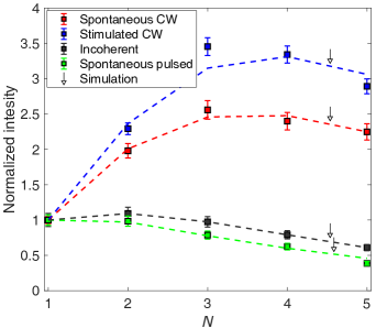
We then investigated the cooperative emission of the ring array by measuring the coincidence rate as a function of the number of coherently pumped resonators. To do this, we excited the input of the sequence and overlapped the spectra of the emitters from to , collecting pairs from port . The coincidence rates versus , normalized with respect to that of source , are reported in Fig.4(red). The rate increases sub-linearly up to , and then slowly decreases as more resonators are added to the sequence.
At first glance this result is puzzling. Indeed, one might argue that even in the case of independent emitters, the probability that at least one ring fires should scale with . However, here we have to consider that the pump and the signal/idler photons are attenuated by each drop event, thus the coincidence rate reaches a maximum, then decreases when the losses prevail. Still, it is not clear whether this result is associated with any cooperative behaviour, for a similar trend could be
also expected for incoherent emission of each ring individually. To test this hypothesis, each source is pumped individually with an input power of , where is the on-resonance drop transmittance. The scaling of the pump power is made necessary to take into account the losses after each drop event. We then measured the coincidence rates , and calculated the expected incoherent rate at the end of the sequence as , where is the effective transmittance of the pair from source to (see calculation in Appendix D). The quantity is reported in Fig.4 (black). The incoherent sum is approximately constant up to , and then drops as the size of the array is increased. This clearly disagrees with the result for the collective excitation of the emitters (red line in Fig.4). and demonstrates the presence of cooperative effects in the array that enhance the pair generation probability.
Following Onodera et al. [25], cooperativity is associated with the impossibility of distinguishing which ring emitted the pair that is detected at the output of the sequence, from which quantum interference arises. In the ideal scenario where all the sources are identical and fully coherent, the pair generation probability is predicted to be enhanced by a factor over that of a single emitter. It is worth to stress that this result does not trivially follows from the intrinsic scaling of SFWM with the system size . Even in a bare waveguide, the SFWM intensity grows as only when photon pairs are spectrally filtered with a bandwidth that is much smaller than the one determined by dispersion, while in the unfiltered case the scaling is [30]. The dependence is rather a consequence of quantum interference. To this end, it is instructive to consider the analogy with the single photon super-radiance in atomic clouds [3], and view super SFWM as an enhanced collective decay process. In this picture, the pump beam interacts with all the rings and probabilistically generates a photon pair in one of them, i.e., it creates an excitation that is symmetrically stored in the array of emitters. In the atomic counterpart, this state corresponds to the case where only one atom is fully excited by the absorption of one photon, but we do not know which one. Then, each resonator can ”spontaneously emit” the pair into the bus waveguide, in the very same way a two level atom can decay into a radiation mode via its electric dipole coupling to the vacuum of the electromagnetic field (indeed, the two processes are described by formally equivalent Hamiltonians [23, 25, 30]). The transition amplitudes associated to those events where pairs generated in source are scattered towards port are all coherent and with a negligible relative phase (see Appendix A for derivation). Constructive interference would then be expected to occur among these transition amplitudes, enhancing the decay process by times compared to the case of an incoherent emission, and completing the analogy with the single photon super-radiance [23, 3]. However, in the real scenario the marginal spectra of photons generated by different rings are partially distinguishable. Indeed, pairs emitted by ring are dropped and filtered times before they reach the end of the sequence, a fact that progressively narrows their spectral linewidth and decreases the effective brightness of the source.
To bring our system closer to the ideal conditions, we considered FWM and suppressed the filtering effect by stimulating the generation of signal photons by resonantly injecting a CW idler seed. As shown in Fig.1(c), the seed is combined to the pump laser using a beamsplitter before entering at the input of the chip. Energy conservation forces the signal beam to have a bandwidth comparable to that of the pump and the idler laser (a few MHz), which is much smaller than that of the resonators, therefore eliminating the filtering issue. The stimulated signal is detected at the output of the sequence using a monochromator coupled to a CCD camera, and its intensity is shown in Fig.4 (blue) as a function of the size of the array. The growth of this curve is super-linear up to , a genuine manifestation of coherent emission of the resonators.
The larger scaling of stimulated FWM with respect to the spontaneous process comes from two contributions. First, the narrowband emission eliminates the effect of spectral filtering. Second, the stimulated process intrinsically scales better with than the spontaneous case, even in absence of spectral filtering; this is due to the different way the losses are impacting the rate of the singles and the coincidences. The first contribution dominates in our experiment (see Appendix C for demonstration). Still, lossess prevent even for the stimulated process to scale with .
We can identify the on-resonance drop transmission as the ultimate factor limiting the full cooperativity of the array. In Appendix C, it is proved that when losses are considered (), the signal intensity scales as . This relation is used to fit the experimental data for stimulated FWM, showing the best agreement (dashed blue line in Fig.4) when , which is close to the measured value. On the contrary, a model based on incoherent emitters predicts a scaling law , which does not reproduce the experimental data for any meaningful value of . To further highlight the critical role of losses on the cooperativity in the spontaneous process, we repeated the experiment using a broadband pulsed pump laser. The (filtered) bandwidth () is intentionally set to be approximately twice the one of the resonators to introduce additional filtering loss at each drop event. As shown in Fig.1(c), this is obtained by filtering a broad-band (few nm) femtosecond laser with a Fiber Bragg Grating and a circulator. As shown in Fig.4 (green), the measured coincidence rates are now much smaller than that of the CW case. To consolidate these observations, we modeled the pair generation process using the method of asymptotic fields described earlier [31]. We leave the detailed derivation to Appendix A, and report here the final expression for the normalized rate , which is given by
| (1) |
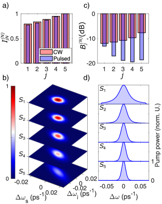
where is the relative (compared to a single resonator) brightness of source as seen from the output of the sequence of rings. The quantity is the indistinguishability between the joint spectral amplitude (JSA) of photon pairs emitted by source and , as seen from the output port [32]. In Fig.5(a) we plot for and , for both CW and the pulsed pumping. The indistinguishability between source and source monotonically increases with . This is due to the spectral filtering on the pairs, which is manifested by the progressive narrowing of the JSA as we proceed backwards from the end of the sequence (Fig.5(b)). As shown in Fig.5(c), the relative brightness is greatly reduced as increases for pulsed pumping, while it increases as increases for CW pumping. This is caused by the spectral filtering on the broadband pump, shown in Fig.5(d), which acts as an excess loss. We used Eq.(1) to simulate the expected rates for both CW and pulsed pumping, leaving only the drop transmittance as a free parameter. We found the best agreement when in the CW case, and in the pulsed case.
It is now natural to ask if a super SFWM regime, i.e., a rate of emission which scales as with , could be reached also in the spontaneous case in lossy integrated systems. By looking at Eq.(1), this is possible if , a requirement that can be met by lowering the drop and the filtering losses. As an example, the first can be reduced by increasing the coupling between the resonator and the waveguide, as the drop transmittance scales as , where , is the ratio between the intrinsic () and extrinsic () quality factors. It can be proved that in the ideal (lossless scenario where , the presence of spectral filtering still limits the scaling to (see Appendix B for demonstration).
This issue could be mitigated by gradually increasing the linewidth of signal/idler resonances along the sequence, for example through an apodization of the quality factors. Improving the super SFWM rate closer to the theoretical limit of could open several perspectives of both technological and fundamental relevance. First, the brightness of the array would be improved without increasing the input pump power, which is appealing for the realization of ultra-bright photon pair sources by preventing the saturation of the pump power induced by nonlinear absorption in silicon [33, 34]. Second, we foresee that by post-selecting a higher number of sources which fire simultaneously, we could use the integrated photonic platform to explore other cooperative regimes of many body physics with high process fidelity. Finally, our results may foster future works exploring the coherent combination of light from several microrings to construct sources based on cooperative super SFWM.
IV Conclusions
In conclusion, we have provided experimental evidence of cooperative emission of photon pairs from an array of microresonators on a silicon photonic chip, bringing the original theoretical study from Onodera et. al [25] from theory to practice.
We identified losses and indistinguishability as the main factors limiting the super SFWM scaling. These could be greatly mitigated by improving the device design. Our work shows that the integrated platform is a reliable alternative to those based on cold matter systems, offering a robust control on the state evolution, design possibilities and intrinsic scalability. The state associated to a single pair emission is in itself linked to intriguing physics, as single photon superradiance [35, 3] or directional spontaneous emission [23]. The natural extension to multiple pair emission opens the possibility of using silicon photonic devices for the emulation of many body atomic systems of increased complexity.
Acknowledgements.
This work has been supported by Ministero dell’Istruzione, dell’ Università e della Ricerca [MIUR grant Dipartimenti di Eccellenza 2018-2022 (F11I18000680001)]. J. E. S. acknowledges support from the Natural Sciences and Engineering Research Council of Canada. The device has been designed using the open source Nazca design™ framework.Appendix A: Model of pair generation from the array of resonators
We used the formalism of asymptotic fields to model SFWM from the array of resonators [31, 36]. We expanded the electric displacement field in terms of asymptotic input fields for the pump, while we used asymptotic output fields for the signal/Idler,
| (2) |
where and are the photon lowering operators at wavevector and frequency for the pump and signal/idler photons respectively. The functions represent the normalized spatial profiles of the asymptotic field in the structure. The integrals in Eq.(2) are performed in the neighbour of , i.e., the wavevectors of the three, not overlapping frequency intervals around the signal, the pump and the idler resonance. With reference to Fig.6(a), the field describes a wave entering at the input port of the array which is routed to the drop of the last ring of the sequence (in the following, all the resonators are assumed to be identical and spectrally overlapped). The energy amplitude inside ring is denoted as . Similarly, the time reversal of the field , shown in Fig.6(b), corresponds to a wave entering from port and leaving the array from the input.
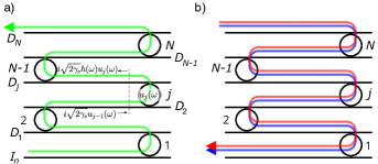
The reason why we consider and not will be clarified later. We stress that the form of the asymptotic fields shown in Fig.6 approximates the real scenario, where photons can also be scattered into the Through ports or away from the chip. In principle, their contribution has to be included to ensure that the system Hamiltonian generates a unitary evolution of the states. However, since we are only interested into those cases where signal/idler pairs leave together ports , we can obtain the same result of the full calculation by using a transfer function relating to that is not energy conserving. The approach is analogous to the one described earlier [37], where the effect of scattering losses in pair generation is accounted for by introducing an effective absorption coefficient in the asymptotic fields. When the expression in Eq.(2) is inserted into the Hamiltonian of the system, we get , where governs the free evolution of the asymptotic fields, while describes the third order nonlinear interaction in the array of rings, which is responsible of SFWM [36, 30]. The operator can be written as
| (3) |
where and
| (4) |
| (5) |
For simplicity we used a scalar form of , keeping only to the contribution of the dominant component of the field. The quantity is a constant related to the nonlinear effective index of the material, the effective area of the waveguide and to the pump power [38]. Due to the form of , the asymptotic output fields enter with a complex conjugate in Eq.(5), which motivates the choice to consider the time reversal of in Fig.6(b). In principle, the volume integral in Eq.(5) should be evaluated both in the rings and in the waveguide sections connecting them. In practice, since the field intensity is more intense inside the resonators, we restrict the calculation to that region. In the case of the pump, we derive the field intensity inside ring starting from the energy amplitude predicted by TCMT [32]; it is given by
| (6) |
where is the incoming wave at the input of ring and can be viewed as a transfer function. By looking at Fig.6(a), the input is given in turn by , where is the separation between the resonators, which inserted into Eq.(6) gives . It is worth noting that , which implies that some photons are lost during the propagation from to . These can either exit via the Through port or be scattered off the chip. We can use this recursive relation times to relate to , i.e., to the excitation amplitude at the input,
| (7) |
Similarly, we can construct an equivalent relation for the asymptotic output fields of the signal and idler inside the rings. This time, the number of resonators preceding is , hence
| (8) |
where has to be considered centered at the resonance frequency of the signal or idler. From now on, we label the transfer function of the three waves as and . The displacement field inside ring is related to [25] by
| (9) |
where is the cavity round trip time, is the azimuthal coordinate along the ring, are the transverse coordinates spanning the waveguide cross section, and is the mode profile. Inserting Eq.(9) into Eq.(5), and using the expressions in Eq.(6-7), we get where is given by
| (10) |
where all the terms that do not depend on or have been factored out to simplify the expression, and we have defined . The quantity enters in the expression of the joint spectral amplitude [25, 38] as
| (11) |
where is the normalized spectral amplitude of the pump, is a constant, and is the pair generation probability from the array of rings. By substituting Eq.(10) into the expression of in Eq.(11) we get , where
| (12) |
and from the normalization condition, , we have
| (13) |
with the definitions
| (14) | ||||
| (15) |
In writing Eq.(13), we replaced the function by the value , since is considered to vary slowly over the wavevector range where the integral in Eq.(12) has not vanishing contributions. This condition holds as long as , where is the coherence length of the FWM interaction.
In our experiment, this quantity is of the order of few cm for signal/idler pairs that are generated within nm of spectral distance from the pump, which justifies the approximation. We can interpret as the pair generation probability of source in the array, and as the indistinguishability between the JSA of source and source (as seen from the output port ). Terms with represent the interference between the amplitude probabilities of generating a pair in ring and , and have a relative phase . Since , we have that , so all these terms interfere constructively.
The coincidence rate between the signal and the idler photons at the output of the sequence is proportional to , hence the normalized rate can be written as
| (16) |
where is the relative (compared to a single resonator) brightness of source as seen from the output of the sequence of rings. This expression coincides with Eq.(1) of the main text. The quantities and have been computed through numerical simulations using Eq.(14,15), and are shown in the Supplemental Fig.3 [29] for both CW and pulsed excitation. Using these values, we fit the scaling laws shown in Fig.4. In all the simulations, the values of the loaded quality factors and the shape of the pump spectra are taken from the experiment, as detailed in the Supplemental Material [29]. We left the drop transmittance as a free parameter, from which the intrinsic quality factor can be computed as . The values of that minimize the least square error with the experimental data are reported in Table 1.
| Process | |
|---|---|
| Stimulated FWM | 0.75 |
| Spontaneous FWM (CW) | 0.8 |
| Spontaneous FWM (pulsed) | 0.79 |
Appendix B: Asymptotic scaling for long sequences of resonators
In this section, we derive the asymptotic behaviour of the pair generation rate for a large number of resonators in the CW regime. This is formally a generalization to a chain of lossy add-drop resonators of the ideal scenario described earlier [25], where a lossless sequence of all-pass resonator was considered. The authors found that under CW pumping, the pair generation probability scales as with the number of resonators. Here we show that without apodization of the resonance linewidth (see main text), the filtering loss limits the asymptotic scaling of the spontaneous rate to , i.e., an intermediate value lying between the fully incoherent case () and the ideal case without spectral filtering [25]. We start by noting that, following Eq.(6) and the discussions above, we can relate the internal energy to the excitation as
| (17) |
where we used and have introduced the drop transmittance , which is given by
| (18) |
By iterating Eq.(17) times, we obtain for the pump internal energy, and for that of the signal/idler. When this expression is plugged into Eq.(5), through the use of Eq.(9) and a little bit of algebra we have
| (19) |
where equals the on resonance transmitted intensity of the resonator at each of the pump, idler, and signal resonant frequencies, while
| (20) |
is a Lorentzian function. In Eq.(20), we write as the frequency shift from the signal resonance at . The modulus square of is then given by
| (21) |
The pair generation probability is proportional to , which demands to calculate the integral of powers of a Lorentzian function. This can be achieved with the aid of the function,
| (22) |
where in the last step we used the asymptotic formula for for the function . Using Eq.(22), the pair generation rate is
| (23) |
The first summation can be approximated with a similar integral,
| (24) |
The second summation scales as the former for large values of , hence the pair generation probability asymptotically scales as with the number of resonators. In the ideal scenario where , which corresponds to the limit of vanishing propagation losses, the spectral filtering ultimately limits the scaling to . In a typical experiment one has , and for such value the asymptotic expressions in Eq.(22) and in Eq.(24) already appliy to a good approximation ( and for , the latter being compared to the asymptotic behaviour ).
Appendix C: Impact of the array losses on the intensity of stimulated and spontaneous four-wave mixing
Here, we give a simplified treatment describing the impact of loss in the scaling of the intensity of stimulated and spontaneous FWM from the array of resonators. We consider a CW excitation and neglect any effect related to spectral filtering and distinguishability from the different sources. With reference to Fig.1(b), the stimulated field amplitude at the output port is given by , where is the contribution of ring to the total field reaching port . By denoting with and the powers of the pump and of the stimulating laser at the input of the sequence, and with the drop transmittance (assumed for simplicity to be equal at both the pump, the signal and the idler wavelengths), we have that the stimulated field immediately after the port is , where incorporates all the factors that do not depend on or . The field is dropped times before it reaches port , hence . The normalized power is then given by
| (25) |
where we used the result from the geometric series . It is worth noting that as . We now compare the scaling of stimulated FWM to that of the spontaneous case. As stated before, we neglect the effect of spectral filtering on the pairs imparted by the cascade of resonators in the sequence. This can be experimentally realized by placing a bandpass filter, with a bandwidth much smaller than that of the resonators, before the detection of the signal and the idler photons. Under these conditions, the amplitude probability of generating a pair at port simplifies to , which after drop events becomes . Note that, in contrast with stimulated FWM, the inclusion of both signal and the idler losses leads to an that does not depend on . The normalized coincidence rate then scales as:
| (26) |
A numerical evaluation (see Supplemental Fig.5 [29]) of for dB and shows that the intensity of stimulated FWM scales slightly better than the spontaneous process (the maximum increase of the efficiency is for ). On the other hand, the ratio between the scaling laws of the two processes exceeds (for ) in the experiment (Fig.4 of the main manuscript), indicating that the filtering losses dominate the drop losses.
Appendix D: Modeling the incoherent emission from the array
In this section we derive an expression for the pair generation probability of the array as if the different rings were emitting incoherently and independently from each other. We also aim to cast this expression in a form that contains quantities accessible from the experiment. The starting point is Eq.(16), where we set for to remove the interference terms. In the experiment we do not have direct access to , since the array geometry prevents us from individually pumping source and collecting pairs from port . What we actually can do is to pump source from port and collect photons from the Through port. This allows to to determine the pair generation probability immediately after port ; we assume equal escape probabilities of photons in the Through and the Drop port, which finds its justification in the symmetric coupling of the ring with the two bus waveguides. From this, we need to compute the effective transmittance of the pair from source to port , in order to correctly scale the pair generation probability and obtain . Mimicking the experimental conditions, we considered a CW pump, which allows us to write Eq.(14) in the form
| (27) |
We now introduce the effective transmittance of the pair from to ,
| (28) |
and insert it into Eq.(27) to get
| (29) |
The quantity in brackets in Eq.(29) is the pair generation probability of source when it is pumped from the input of the array, and when the emitted pairs are collected immediately after port . Denoting by the related coincidence rate, we have
| (30) |
This expression is used to estimate the normalized rate of incoherent emission from the array. In order to measure , we injected light into port , and scaled the power according to , where is the on-resonance drop transmittance. This emulates the drop events of the pump from the input to source .
References
- Dicke [1954] R. H. Dicke, Coherence in spontaneous radiation processes, Phys. Rev. 93, 99 (1954).
- Gross and Haroche [1982] M. Gross and S. Haroche, Superradiance: An essay on the theory of collective spontaneous emission, Phys. Rep. 93, 301 (1982).
- Scully and Svidzinsky [2009] M. O. Scully and A. A. Svidzinsky, The super of superradiance, Science 325, 1510 (2009).
- Benedict et al. [2018] M. G. Benedict, A. M. Ermolaev, V. Malyshev, I. Sokolov, and E. D. Trifonov, Super-radiance: Multiatomic coherent emission (CRC Press, 2018).
- González-Tudela et al. [2015] A. González-Tudela, V. Paulisch, D. Chang, H. Kimble, and J. I. Cirac, Deterministic generation of arbitrary photonic states assisted by dissipation, Phys. Rev. Lett. 115, 163603 (2015).
- Asenjo-Garcia et al. [2017] A. Asenjo-Garcia, M. Moreno-Cardoner, A. Albrecht, H. Kimble, and D. E. Chang, Exponential improvement in photon storage fidelities using subradiance and “selective radiance” in atomic arrays, Phys. Rev. X 7, 031024 (2017).
- Facchinetti et al. [2016] G. Facchinetti, S. D. Jenkins, and J. Ruostekoski, Storing light with subradiant correlations in arrays of atoms, Phys. Rev. Lett. 117, 243601 (2016).
- Bohnet et al. [2012] J. G. Bohnet, Z. Chen, J. M. Weiner, D. Meiser, M. J. Holland, and J. K. Thompson, A steady-state superradiant laser with less than one intracavity photon, Nature 484, 78 (2012).
- Paulisch et al. [2019] V. Paulisch, M. Perarnau-Llobet, A. González-Tudela, and J. I. Cirac, Quantum metrology with one-dimensional superradiant photonic states, Phys. Rev. A 99, 043807 (2019).
- Araújo et al. [2016] M. O. Araújo, I. Krešić, R. Kaiser, and W. Guerin, Superradiance in a large and dilute cloud of cold atoms in the linear-optics regime, Physical review letters 117, 073002 (2016).
- Skribanowitz et al. [1973] N. Skribanowitz, I. Herman, J. MacGillivray, and M. Feld, Observation of dicke superradiance in optically pumped hf gas, Physical Review Letters 30, 309 (1973).
- Srivathsan et al. [2013] B. Srivathsan, G. K. Gulati, B. Chng, G. Maslennikov, D. Matsukevich, and C. Kurtsiefer, Narrow band source of transform-limited photon pairs via four-wave mixing in a cold atomic ensemble, Physical review letters 111, 123602 (2013).
- Goban et al. [2015] A. Goban, C.-L. Hung, J. Hood, S.-P. Yu, J. Muniz, O. Painter, and H. Kimble, Superradiance for atoms trapped along a photonic crystal waveguide, Phys. Rev. Lett. 115, 063601 (2015).
- Lukin et al. [2022] D. M. Lukin, M. A. Guidry, J. Yang, M. Ghezellou, S. D. Mishra, H. Abe, T. Ohshima, J. Ul-Hassan, and J. Vučković, Optical superradiance of a pair of color centers in an integrated silicon-carbide-on-insulator microresonator, arXiv preprint arXiv:2202.04845 (2022).
- Wang et al. [2020] Z. Wang, H. Li, W. Feng, X. Song, C. Song, W. Liu, Q. Guo, X. Zhang, H. Dong, D. Zheng, et al., Controllable switching between superradiant and subradiant states in a 10-qubit superconducting circuit, Phys. Rev. Lett. 124, 013601 (2020).
- Mlynek et al. [2014] J. A. Mlynek, A. A. Abdumalikov, C. Eichler, and A. Wallraff, Observation of dicke superradiance for two artificial atoms in a cavity with high decay rate, Nat. Commun. 5, 1 (2014).
- Kim et al. [2018] J.-H. Kim, S. Aghaeimeibodi, C. J. Richardson, R. P. Leavitt, and E. Waks, Super-radiant emission from quantum dots in a nanophotonic waveguide, Nano Lett. 18, 4734 (2018).
- Koong et al. [2022] Z. X. Koong, M. Cygorek, E. Scerri, T. S. Santana, S. I. Park, J. D. Song, E. M. Gauger, and B. D. Gerardot, Coherence in cooperative photon emission from indistinguishable quantum emitters, Sci. Adv. 8, eabm8171 (2022).
- Grim et al. [2019] J. Q. Grim, A. S. Bracker, M. Zalalutdinov, S. G. Carter, A. C. Kozen, M. Kim, C. S. Kim, J. T. Mlack, M. Yakes, B. Lee, et al., Scalable in operando strain tuning in nanophotonic waveguides enabling three-quantum-dot superradiance, Nat. Mater. 18, 963 (2019).
- Guerin et al. [2016] W. Guerin, M. O. Araújo, and R. Kaiser, Subradiance in a large cloud of cold atoms, Phys. Rev. Lett. 116, 083601 (2016).
- Sipahigil et al. [2016] A. Sipahigil, R. E. Evans, D. D. Sukachev, M. J. Burek, J. Borregaard, M. K. Bhaskar, C. T. Nguyen, J. L. Pacheco, H. A. Atikian, C. Meuwly, et al., An integrated diamond nanophotonics platform for quantum-optical networks, Science 354, 847 (2016).
- Angerer et al. [2018] A. Angerer, K. Streltsov, T. Astner, S. Putz, H. Sumiya, S. Onoda, J. Isoya, W. J. Munro, K. Nemoto, J. Schmiedmayer, et al., Superradiant emission from colour centres in diamond, Nat. Phys. 14, 1168 (2018).
- Scully et al. [2006] M. O. Scully, E. S. Fry, C. R. Ooi, and K. Wódkiewicz, Directed spontaneous emission from an extended ensemble of n atoms: Timing is everything, Phys. Rev. Lett. 96, 010501 (2006).
- Schneble et al. [2003] D. Schneble, Y. Torii, M. Boyd, E. W. Streed, D. E. Pritchard, and W. Ketterle, The onset of matter-wave amplification in a superradiant bose-einstein condensate, Science 300, 475 (2003).
- Onodera et al. [2016] T. Onodera, M. Liscidini, J. Sipe, and L. Helt, Parametric fluorescence in a sequence of resonators: An analogy with Dicke superradiance, Phys. Rev. A 93, 043837 (2016).
- Llewellyn et al. [2020] D. Llewellyn, Y. Ding, I. I. Faruque, S. Paesani, D. Bacco, R. Santagati, Y.-J. Qian, Y. Li, Y.-F. Xiao, M. Huber, et al., Chip-to-chip quantum teleportation and multi-photon entanglement in silicon, Nat. Phys. 16, 148 (2020).
- Azzini et al. [2012] S. Azzini, D. Grassani, M. Galli, L. C. Andreani, M. Sorel, M. J. Strain, L. Helt, J. Sipe, M. Liscidini, and D. Bajoni, From classical four-wave mixing to parametric fluorescence in silicon microring resonators, Opt. Lett. 37, 3807 (2012).
- Carolan et al. [2019] J. Carolan, U. Chakraborty, N. C. Harris, M. Pant, T. Baehr-Jones, M. Hochberg, and D. Englund, Scalable feedback control of single photon sources for photonic quantum technologies, Optica 6, 335 (2019).
- [29] See supplemental material, which contanins refs. [32,39], for sample fabrication and geometry, experimental methods, linear device characterization and theoretical modeling of photon pair generation.
- Helt et al. [2012a] L. G. Helt, M. Liscidini, and J. E. Sipe, How does it scale? comparing quantum and classical nonlinear optical processes in integrated devices, J. Opt. Soc. Am. B 29, 2199 (2012a).
- Liscidini et al. [2012] M. Liscidini, L. Helt, and J. Sipe, Asymptotic fields for a Hamiltonian treatment of nonlinear electromagnetic phenomena, Phys. Rev. A 85, 013833 (2012).
- Borghi [2020] M. Borghi, Phase-resolved joint spectra tomography of a ring resonator photon pair source using a silicon photonic chip, Opt. Express 28, 7442 (2020).
- Engin et al. [2013] E. Engin, D. Bonneau, C. M. Natarajan, A. S. Clark, M. G. Tanner, R. H. Hadfield, S. N. Dorenbos, V. Zwiller, K. Ohira, N. Suzuki, et al., Photon pair generation in a silicon micro-ring resonator with reverse bias enhancement, Opt. Express 21, 27826 (2013).
- Husko et al. [2013] C. A. Husko, A. S. Clark, M. J. Collins, A. De Rossi, S. Combrié, G. Lehoucq, I. H. Rey, T. F. Krauss, C. Xiong, and B. J. Eggleton, Multi-photon absorption limits to heralded single photon sources, Scientific reports 3, 1 (2013).
- Tighineanu et al. [2016] P. Tighineanu, R. S. Daveau, T. B. Lehmann, H. E. Beere, D. A. Ritchie, P. Lodahl, and S. Stobbe, Single-photon superradiance from a quantum dot, Phys. Rev. Lett. 116, 163604 (2016).
- Yang et al. [2008] Z. Yang, M. Liscidini, and J. E. Sipe, Spontaneous parametric down-conversion in waveguides: a backward Heisenberg picture approach, Phys. Rev. A 77, 033808 (2008).
- Banic et al. [2021] M. Banic, L. Zatti, M. Liscidini, and J. Sipe, Modeling nonlinear optics in lossy microring systems: two strategies, arXiv preprint arXiv:2111.14711 (2021).
- Helt et al. [2012b] L. Helt, J. Sipe, and M. Liscidini, Super spontaneous four-wave mixing in single-channel side-coupled integrated spaced sequence of resonator structures, Opt. Lett. 37, 4431 (2012b).
- Bellegarde et al. [2018] C. Bellegarde, E. Pargon, C. Sciancalepore, C. Petit-Etienne, V. Hugues, D. Robin-Brosse, J.-M. Hartmann, and P. Lyan, Improvement of sidewall roughness of submicron soi waveguides by hydrogen plasma and annealing, IEEE Photonics Technol. Lett. 30, 591 (2018).