Electrode effects on the observability of destructive quantum interference in single-molecule junctions
Abstract
Destructive quantum interference (QI) has been a source of interest as a new paradigm for molecular electronics as the electronic conductance is widely dependent on the occurrence or absence of destructive QI effects. In order to interpret experimentally observed transmission features, it is necessary to understand the effects of all components of the junction on electron transport. We perform non-equilibrium Green’s function calculations within the framework of density functional theory to assess the structure-function relationship of transport through pyrene molecular junctions with distinct QI properties. The chemical nature of the anchor groups and the electrodes controls the Fermi level alignment, which determines the observability of destructive QI. A thorough analysis allows to disentangle the transmission features arising from the molecule and the electrodes. Interestingly, graphene electrodes introduce features in the low-bias regime, which can either mask or be misinterpreted as QI effects, while instead originating from the topological properties of the edges. Thus, this first principles analysis provides clear indications to guide the interpretation of experimental studies, which cannot be obtained from simple Hückel model calculations.
Introduction
In recent years it has been established, both theoretically and experimentally, that the electron transport properties in single-molecule junctions are dominated by quantum mechanical effects. In particular, as the propagation of electrons can be described in terms of de Broglie waves, the electronic transmission function exhibit quantum interference (QI) which results in constructive (CQI) or destructive (DQI) interference patterns. Lambert (2015) While CQI results in an enhancement of the electron transmission probability, the hallmark of destructive QI is the presence of antiresonances in the electronic transmission function which can significantly reduce the conductance. Such QI effects are common in some classes of -conjugated systems, which are characterized by delocalized electronic states.
As QI effects can be tailored by chemical Markussen et al. (2011); Guédon et al. (2012) and physical Frisenda et al. (2016); Caneva et al. (2018); Stefani et al. (2018); Sowa et al. (2018); Li et al. (2019, 2019) mechanisms and can survive even at room temperature, Wang et al. (2020); Markussen et al. (2011) they are relevant for the realization of functional nanoelectronic applications, such as memory cells, Stadler et al. (2003) logic gates, Stadler et al. (2004) single-molecule transistors, Stafford et al. (2007); Jia et al. (2018) molecular switches, Markussen et al. (2010); Daaoub et al. (2020); Greenwald et al. (2020) and spin filters. Saraiva-Souza et al. (2014); Valli et al. (2018, 2019) Particularly interesting is the potential role of QI in thermoelectric devices, Stadler and Markussen (2011); Markussen (2013); Famili et al. (2017); Klöckner et al. (2017); Miao et al. (2018); Sadeghi (2019); Sangtarash et al. (2018) where both CQI and DQI have been proposed to improve device efficiency, as the former can directly enhances the electrical conductivity Wang et al. (2020) whereas the presence of a sharp DQI antiresonance can affect the Seebeck coefficient. Strange et al. (2015); Klöckner et al. (2017); Miao et al. (2018); Grace et al. (2020)
Moreover, QI phenomena are not limited to single molecules, but have also been observed in other -conjugated systems, including a variety of graphene nanostructures, such as nanoconstrictions, Gehring et al. (2016) nanoribbons, Rosales et al. (2009); Calogero et al. (2019) nanoflakes, Valli et al. (2018, 2019); Niţă et al. (2020) and carbon nanotubes, Tsuji et al. (2007) as well as metal-organic complexes, such as porphyrin Nozaki et al. (2015); Richert et al. (2017) and ferrocene Zhao et al. (2017); Zhao and Stadler (2019); Camarasa-Gómez et al. (2020) molecules, and in self-assembled monolayers of aromatic molecular cores. Wang et al. (2020) The possibility to exploit QI effects in molecular junctions with graphene functional blocks is highly desirable to pave the path towards an environment-friendly nanotechnology with biodegradable and inexpensive materials. Graphene has already been employed as a protective layer for metallic electrodes Hüser and Solomon (2015) and to realize asymmetric junctions. Zhang et al. (2016, 2018); Tao et al. (2019); He et al. (2020) Another advantage of graphene is that present technologies allow the realization of atomically precise junctions, Cai et al. (2010); Chen et al. (2015); Caneva et al. (2018); El Abbassi et al. (2019); Yang et al. (2020) which, at the same time, offers mechanical stability beyond room temperature Prins et al. (2011) and a higher degree of experimental reproducibility, which is crucial in order to achieve a precise control over QI phenomena. However, it is also known that graphene electrodes introduce additional transmission channels, which can dominate in the low-bias regime and potentially obscure molecule-intrinsic features. Ryndyk et al. (2012); Gehring et al. (2017) In this work we carry out a systematic analysis which allows us to disentangle the features arising from the molecule and the electrodes.
Hitherto, a clear relation between the structure and the QI properties of a junction remains elusive. For this reason, the ability to predict the occurrence of an antiresonance and to understand its dependence on the chemical composition of the molecular junction plays a pivotal role for developing novel technologies based on QI. A few techniques, based on simplified model assumptions, allow to predict QI effects on the basis of graphical, Markussen et al. (2010); Stuyver et al. (2015); O’Driscoll and Bryce (2021) diagrammatic, Pedersen et al. (2015) topological, Geng et al. (2015); Tsuji et al. (2016, 2018) or symmetry Zhao et al. (2017); Valli et al. (2018, 2019) considerations, without the need of numerically expensive first-principles electron transport calculations. While the value of the predictive power of such back of the envelope techniques is undeniable, they are nevertheless unable to capture the detailed effects of the chemical nature of all junction components, including the leads and the linker groups, on the QI features.
In an attempt to bridge the worlds of molecular junctions and graphene with this perspective in mind, we present a systematic analysis of the impact of different anchor groups and electrodes on the QI features. To this end, we consider molecule junctions with a pyrene core, which produces specific and predictable QI patterns, and due to its nature as a polycyclic aromatic hydrocarbon, can also be considered as a minimal graphene-like functional block for nanoelectronics. Sangtarash et al. (2015) Our starting point is a prototypical setup in which the pyrene subunit is attached to Au electrodes with thiol anchoring groups. We explore the effect of subsequently changing the anchoring groups and the electrodes to build a hydrocarbon junction, which is relevant for understanding the electron transport through graphene nanoconstrictions. Specifically, we substitute thiol- with acetylene-terminated linkers and analyze the changes in the transport properties due to the direct Au-C bonds and the charge redistribution within the junction. Next, we substitute the Au electrodes with graphene nanoribbons (GNRs). While the featureless density of states of Au electrodes close to the Fermi level have little effect on the shape of the transmisson function, the electronic properties of graphene nanostructures are strongly affected by the topology of their edges. We shall see that this has profound consequences for the electron transport through the junction, in particular concerning the observability of DQI. By considering graphene electrodes with different size, we are able to disentangle unambiguously the transport features that are intrinsic to the molecule from those stemming from the chemical and topological nature of the electrodes.

QI in molecular junctions with pyrene core
In the following, we consider molecular junctions where a pyrene core is connected to the electrodes in two different configurations via propynylbenzene linkers with thiol- and acetylene-terminated anchor groups, as shown schematically in Fig. 1.
In a realistic scenario, one should expect that the transport properties of a molecular junction are determined by the nature of the linkers and the anchor groups, as well as the electrodes, besides the position of the contact atoms on the -conjugated molecule itself. In general, it is difficult to establish a clear relation between the structure of its components and the QI properties of a molecular junction. Graphical methods Stadler et al. (2004); Markussen et al. (2010); Pedersen et al. (2015) allow, to some extent and on qualitative grounds, to predict the occurrence of QI antiresonances, but become hardly applicable with in complex systems. For this reason our analysis of QI features of pyrene molecular junctions is twofold. First, we focus on the pyrene core and we employ a graphical scheme and calculate the transmission function within a simple Hückel model (SHM), to predict and demonstrate that the aromatic molecular subunit is the source of DQI. For a quantitative analysis we rely on density functional theory (DFT) calculations in combination with non-equilibrium Green’s function (NEGF) formalism, which allows us not only to verify the qualitative predictions, but also to investigate the quantitative effect of different anchor groups and electrodes on the QI features.
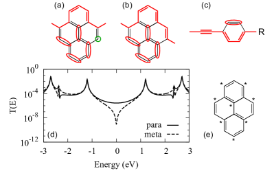
We apply the graphical scheme Stadler et al. (2004); Markussen et al. (2010) to the pyrene core connected in the meta- and para-configurations. The scheme prescribes to draw a continuous path through neighboring atoms from the left to the right lead. No DQI is predicted if such a path crosses all sites of the molecule, or if the remaining sites can be grouped into either pairs or closed loops (red ellipses). Representative paths for the meta- and para-configurations are shown in Figs. 2(a,b), respectively. It is easy to convince oneself that any possible path in the meta configuration leave at least an unpaired site (green circle). Hence, we predict the occurrence of a QI antiresonance in the meta configuration. Including the linkers (with either thiol- or acetylene-termination) in the graphical scheme do not change this conclusion, since linear chains and para-connected benzene rings do not result in DQI, see Fig. 2(c) for the corresponding graphical analysis. Markussen et al. (2010)
The graphical predictions can be easily verified by considering a SHM for the pyrene junction. We set the energy of the C 2 atomic orbitals (AOs) to zero and assume a overlap between neighboring AOs of eV, which is a typical value for graphene, Castro Neto et al. (2009) so that the Hamiltonian of the SHM is proportional to pyrene’s adjacency matrix as with for AOs and sharing a bond, and zero otherwise. Tsuji et al. (2018) The retarded Green’s function of the molecule reads
| (1) |
and the Landauer transmission function Landauer (1957) is given by
| (2) |
where denotes the coupling to either the left (L) or right (R) lead in terms of the corresponding embedding self-energy. As pyrene is contacted to the leads through a single Hückel AO, each matrix has a single non-zero matrix element, and , respectively, which we assume to be energy independent (wide-band limit approximation). The transmission function hence reduces to
| (3) |
and displays resonances in correspondence to the energy Hückel molecular orbitals (MOs) of pyrene. In the meta configuration, the transmission function also exhibits an antiresonance in the middle of the HOMO-LUMO gap (i.e., at ). The antiresonance orginates from DQI, in complete agreement with the scenario predicted within the graphical method.
Analogous conclusions can be drawn from the Coulson-Rushbrooke pairing theorem, Zhao et al. (2017) which states that for alternant hydrocarbons, when the contact sites and belong to the same sublattice, the contribution to the Green’s function coming from the MOs cancels pairwise. Each pair is formed by an occupied and an unoccupied MO. Then, the spectral representation of the Green’s function in the MO basis reads
| (4) |
where is the coefficient of MO at site and the number of MOs in the Hamiltonian. The pairing theorem predicts that for alternant hydrocarbons each pair fulfills the conditions and that all coefficient in one sublattice have opposite sign between the occupied and unoccupied MOs, then for each the contribution of the pair to the sum in Eq. (4) cancels exactly at . Zhao et al. (2017) In the meta configuration, and belong to the same sublattice of the pyrene molecule, as shown in Fig. 2(e), and the Coulson-Rushbrooke predicts a QI antiresonance at the Fermi level, in agreement with the graphical scheme and the SHM calculation.
DFT+NEGF Electron transport calculations
The above analysis establishes clearly the occurrence of DQI depends on the position of the contact atoms on the pyrene core. While this scenario is qualitatively robust, we shall see in the following that the details of the chemical bonding between the molecule and the electrodes, as well as the physical properties of the electrodes, which can be addressed within DFT, can drastically affect the observability of DQI in the transmission function.
Computational details
We investigate the transport properties of molecular junctions with pyrene core within the DFT+NEGF formalism, Brandbyge et al. (2002); Xue et al. (2002) as implemented within the Atomic Simulation Environment Larsen et al. (2017) (ASE) and the GPAW software package.Mortensen et al. (2005); Enkovaara et al. (2010) The transmission function is calculated according to Eq. (2) where the Green’s function is evaluated on the whole DFT basis set for the scattering region. The coupling matrix is obtained from the surface Green’s function of the leads and the couplings between the basis function of the lead and scattering regions. The transport Hamiltonian of each structure is evaluated in a local combination of atomic orbitals (LCAO) Larsen et al. (2009) double- polarized basis, with a Perdew-Burke-Ernzerhof (PBE) parameterization for the exchange-correlation functional, and a sampling of 0.2 Å grid spacing. For each molecular configuration we perform an atomic optimization of the molecule in vacuum until the value of the Hellmann–Feynman forces are below eV/Å.
In the case of Au electrodes, the scattering region consists of seven layers of Au(111). The linkers are connected via anchoring groups to Au adatoms placed in the hollow position of the Au(111) surface. We take a typical bonding distances of Å for thiol-terminated linkers Zhao et al. (2017); Stadler et al. (2005) and Å for acetylene-terminated linkers. Liu et al. (2013) The scattering region is sampled with a Monkhorst-Pack mesh, and the leads are sampled with a Monkhorst-Pack mesh, where denotes the transport direction.
In the case of graphene electrodes, GNRs typically have either a zigzag (ZZ) or an armchair (AC) termination. We consider the GNRs with ZZ edges and denote periodic structures with width N as N-zGNRs, following the standard nomenclature in the literature. The dangling bonds at the graphene edges are passivated with H atoms. For the portion of GNRs included in the scattering region, we assume a rectangular termination, which can be expected for atomically-precise GNRs obtained though bottom-up synthesis by polymerization. Cai et al. (2010) Hence, in this configuration, at the junction interface between the GNRs and the molecular bridge, zGNRs have a transverse edge with AC topology (on the contrary, aGNRS have a transverse edge with ZZ topology). For graphene electrodes, a natural choice is to connect the molecule to the leads by replacing one of the H atoms passivating the edge on each side with the acetylene-terminated linkers, with a bonding distance Å. The scattering region is sampled with a Monkhorst-Pack mesh, and the leads consist of GNR unit cells sampled with a Monkhorst-Pack mesh, where denotes the transport direction. For infinitely-wide GNRs (semi-infinite graphene sheet) we impose periodic boundary conditions along the in-plane direction () transverse to the transport direction, which we sample with a Monkhorst-Pack mesh with up to -points.
Results and Discussion
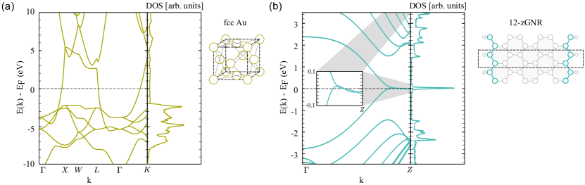
From the atomic and electronic structure perspective, Au and graphene are completely different materials. While for Au electrodes the transmission close to the Fermi level is dominated by a single transmission channel with predominant Au 6s character, Cuevas and Scheer (2010); Jia and Guo (2013) the electronic properties of graphene critically depend on the topology of the edges. In particular, it is well known that GNRs with ZZ termination support non-dispersive states localized near the edges. Hence, the zGNRs that we consider in the following are metallic, while aGNRs are typically semiconductors. Wakabayashi et al. (1999); Son et al. (2006) Moreover, aGNR electrodes have transverse ZZ edge states that decay very slowly into the bulk, Li et al. (2014, 2015) making the correct computational treatment with first principle methods very challenging. To illustrate the properties of the electrodes, in Fig. 3 we compare the bandstructure and corresponding density of states (DOS) of fcc Au, to those of periodic zGNR.
Another difference between Au and graphene electrodes is that GNRs with ZZ edges have a tendency towards magnetic ordering. Hence, in order to complete our analysis, we also discuss the effect of a spin-symmetry breaking on the DQI properties of pyrene molecular junction.
Au electrodes
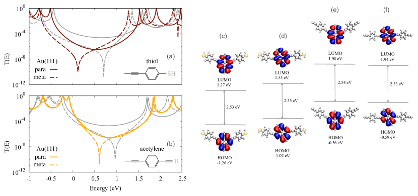
We first discuss the case in which the molecule bridges Au electrodes. The transmission as a function of energy of the incoming electrons for the pyrene connected in the meta- and para-configurations with either thiol or acetylene anchoring groups is shown in Fig. 4(a,b), respectively. The transmission function is similar in all cases, with the main difference being the antiresonance within the HOMO and LUMO gap present in the meta configuration. This is in complete agreement with the previous analysis with the graphical scheme, the Coulson-Rushbrooke pairing theorem, and the SHM. However, the conductance of the junction also strongly depends on the relative positions of the HOMO, the LUMO, and the antiresonance with respect to the Fermi level, which we are going to analyze in detail in the following.
In all cases, the antiresonance is closer to the HOMO than to the LUMO. For thiol-terminated linkers, eV is also close to the Fermi level , whereas for acetylene-terminated linkers there is a shift to higher energies, resulting in eV. The most striking difference between the two cases is the relative position of the Fermi level within the HOMO-LUMO gap. In order to shed light on this, we perform a Bader charge analysis Tang et al. (2009) for the free molecule and the junction with both linkers, because the Fermi level alignment is closely related to the zero-bias charge transfer. Stadler and Jacobsen (2006); Stadler (2007, 2010); Kastlunger and Stadler (2013) The HOMO-dominated profile in the case of acetylene linkers is coming from the negatively charged molecule after the placement in between the leads, which shifts the position of HOMO and LUMO to higher energies, with respect to thiol linkers. Stadler and Jacobsen (2006); Stadler (2007) When we analyze the case with thiol linkers, there is a clear difference in the Fermi level alignment of the meta- and para-configurations. This can be explained by considering the larger electron transfer from the molecule towards the electrodes in the meta with respect to the para configuration as reported in Table 1. In the case of acetylene linkers instead, the charge transfer is negative, corresponding to electron transfer from the electrodes to the molecule. However, there is no direct relation between and and the molecular level position cannot be fully explained by net charge transfer alone, but the molecular dipole moments, can possibly account for it. The dipole moment is larger in the meta configuration and it is orientated within the plane of the molecule and orthogonal to the transport direction (see Table 1).
| (eV) | () | (D) | ||
|---|---|---|---|---|
| Thiol | meta | -0.97 | 0.39 | 0.33 |
| para | -0.72 | 0.16 | 0.19 | |
| Acetylene | meta | -0.20 | -0.38 | 0.14 |
| para | -0.20 | -0.50 | 0.01 |
It is possible to qualitatively describe the QI effects taking into account only the symmetry properties of the pyrene core. This analysis is also consistent with our DFT calculations. We diagonalize the sub-block of the transport Hamiltonian of the pyrene core to obtain the projected MOs. We can calculate an approximate transmission function selecting the two pairs of MOs closest to the Fermi level, i.e., , HOMO, LUMO, and and cutting out the rest. Stadler (2009); Guédon et al. (2012); Zhao et al. (2017); Gandus et al. (2020) As shown in Fig. 4(a,b) with grey lines, the contribution of these two pairs is sufficient to qualitatively reproduce the antiresonance. The approximate transmission function shows a good qualitative agreement with the one from the original transport Hamiltonian but the position of the antiresonance and the Fermi level alignment are more sensitive to such simplifications.
The symmetry of the MOs carries relevant information on QI. According to the Coulson-Rushbrook pairing theorem, the antiresonance is a consequence of pairwise cancellation of the contributions of the MOs to the transmission. The frontier MOs of the pyrene core are shown in Figs. 4(c-f) for thiol- and acetylene-anchoring group in the meta- and para-configurations. In the case of thiol anchoring groups, the signs of the amplitudes of the eigenvector at the positions where pyrene is connected to the linkers are opposite for both the HOMO and the LUMO in the meta configuration. Hence, we expect a cancellation of the contribution of the frontier MOs in the transmission function, resulting in an antiresonance at some energy , not necessarily at the Fermi level, or mid-gap as in the SHM calculation, since the spectrum is not particle-hole symmetric. Instead, in the para configuration, the amplitude of the LUMO has the same sign at the contact sites, and therefore there is no cancellation in the transmission. When we substitute thiol- with acetylene-group as anchoring units, the same symmetry considerations hold. This suggests that while the origin of the QI phenomena does not depend on the nature of the linkers and anchoring groups, the energy at which the contributions from all MOs cancels is related in a non-trivial way to the chemical nature and the electronic structure properties of all the components of the junction.
Graphene electrodes
We examine now the case in which the pyrene molecule is connected to graphene electrodes via acetylene-terminated linkers. The schematic representations of the junctions with GNR electrodes are shown in Fig. 5(a) where the edges transverse and parallel to the transport direction are highlighted in color. As anticipated, zGNRs have AC edges transverse to the transport direction. In order to assess the effect of edge size and topology on DQI, we consider zGNRs with different widths.
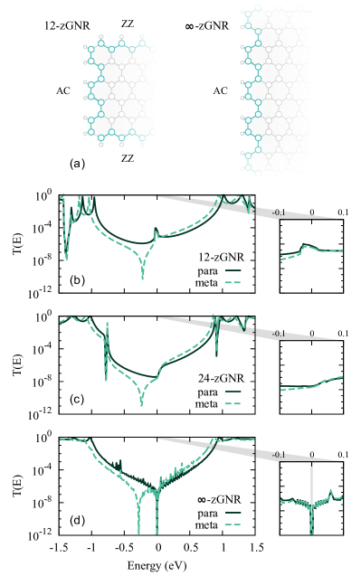
Since with Au electrodes the QI properties arise from the position of the contact atoms in the pyrene, it is reasonable to expect similar features also for graphene electrodes, and an antiresonance is found indeed only for the meta-connected structures. In contrast to the Au electrodes, in which the transmission is HOMO-dominated, here the Fermi level is located close to the middle of the HOMO-LUMO gap and the antiresonance is below . This is not surprising considering that with GNR electrodes, the junction is hydro-carbon throughout and the charge distribution between the molecule and the leads is expected to be uniform. Alqahtani et al. (2018)
In all transmission functions showed in Fig. 5, there are features at the Fermi level, which were absent in the case of Au electrodes. The most natural explanation is that these features stem from graphene edge states. Indeed, the shape of the transmission reflects the presence of both ZZ and AC edges, in a way that depends on the width and the topology of the electrodes. In Figs. 5(b), we observe a resonance at the Fermi level, which indicates a transmission mechanism involving the edge states of the 12-zGNRs. The transmission feature is significantly broad due to the high DOS of the zGNR leads. Some feature, albeit not a resonance is also observe in Fig. 5(c), for the 24-zGNRs. We speculate the overlap between the edge state and the states of the molecular bridge decreases by increasing the width of the zGNR. Eventually, for -zGNR, the transmission function in Fig. 3(c) recovers a V-shape, reminiscent of the DOS of bulk graphene, but it exhibits a gap at the Fermi level (see inset) due to the presence of the transverse edge of the electrode, which has AC character.
Effect of DQI on the I-V characteristics
In an experimental setup, the current-voltage (I-V) characteristics is measured rather than the transmission function. In order to draw conclusions on the observability of DQI effects, we evaluate the electric current (per spin) as
| (5) |
where is the electric charge and the Planck constant. The Fermi distribution function of the source (S) and drain (D) electrodes are given by
| (6) |
where is the Boltzmann constant and is the symmetric bias drop between source and drain. In the calculations, we assume the thermal broadening of the Fermi distribution to be meV and the current is evaluated neglecting the bias dependence of the transmission function, i.e., . In the following, we also look at the differential conductance as a function of both bias () and gate () voltages.
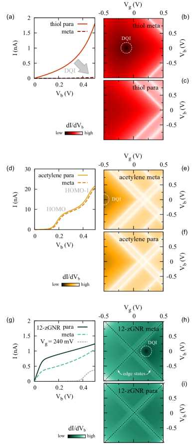
The calculated I-V characteristics and the differential conductance maps for the junctions with Au and zGNR electrodes reveal the qualitative relationship between the transmission and the transport features. The results are presented in Fig. 6. In the case of Au electrodes, the outcome is quite interesting. For all combinations of contact configurations, the HOMO-LUMO gap is very similar, while the junctions with acetylene linkers exhibit an overall much higher current compared to the thiol ones, reaching the order of a few A, see Figs. 6(a,d). This is related to the close proximity of the HOMO to the Fermi level and its wider peak in the transmission function for this linker type. Schwarz et al. (2014) As a consequence, the meta- and para-configurations display very similar I-V characteristics since the effect of DQI is negligible with respect to the resonant contribution of the HOMO. The current displays clear steps in correspondence to the MOs entering the bias window, as indicated in Fig. 6(d). For thiol-terminated linkers, the combination of two effects, i.e., the Fermi level being closer to the middle of the HOMO-LUMO gap and closer to the antiresonance, results in a large difference in the I-V characteristics of the meta- and para-configurations. In Figs. 6(b,c), we show the map of the differential conductance, where the effects of DQI is clearly visible, by comparing the meta- and para-configurations for this combination of electrodes and anchoring groups. The bright lines in the I-V characteristics correspond to the resonances of the MOs.
It is interesting to observe the effect of edge topology of the graphene electrodes on the I-V characteristics. The transmission features close to the Fermi level, originating from the zGNR edge states, appear in both meta- and para- configurations. As a consequence, in both cases we observe a metallic-like I-V characteristics and QI effects do not play an important role. However, for devices based on graphene, and in general 2D-materials, gating is a viable strategy to improve device performances. Specifically, in order to enhance the effects of DQI, one can introduce an external electric field to align the Fermi level to the antiresonance. Applying a gate voltage mV to the junctions with zGNR electrodes, results in a strongly suppressed current, see grey dashed line in Fig. 6(g). This allows one to clearly distinguish the I-V characteristics of the configuration with DQI from the other. In Figs. 6(h,i) we show the map of the differential conductance. The resonances corresponding to the edge states are clearly visible for both meta- and para-configurations while suppression due to DQI is clearly identified as a single dark spot at mV.
Effects of edge magnetism in graphene
While the experimental evidence of magnetism in graphene nanostructures Magda et al. (2014); Slota et al. (2018) is still controversial, from the theoretical point of view it is well established that zGNRs have a tendency towards magnetic order. When the spin symmetry is lifted, the GNR orders according to a Néel antiferromagnetic (AF) pattern, which results in ferromagnetically (FM) aligned ZZ edges, due to the local sublattice imbalance. Opposite edges display opposite magnetization, yielding a global singlet (S=0) and thus fulfilling Lieb’s theorem. The magnetic moments are rapidly suppressed towards the bulk, as well as at AC defects and corners, where the atoms from different sublattices are paired. The magnetic structure of zGNRs has been widely discussed in the literature, and it has been shown to remain qualitatively unchanged also when a local electron-electron interactions is included explicitly within DFT+U, Kabir and Saha-Dasgupta (2014); Ganguly et al. (2017) a mean-field Hubbard model, Fernández-Rossier and Palacios (2007); Hu et al. (2017) and within more sophisticated many-body techniques. Feldner et al. (2011, 2010); Valli et al. (2016, 2018); Baumann et al. (2020); Phùng et al. (2020) Hence, the following discussion can be regarded as of general relevance for the interplay between DQI and edge magnetism.
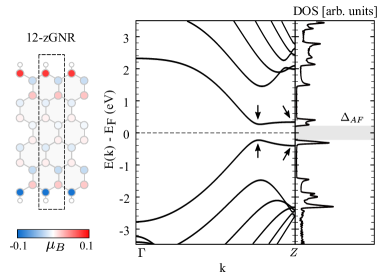
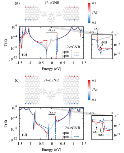
For the sake of completeness, in Fig. 7 we show the bandstructure of periodic 12-zGNR and the spatial distribution of the magnetic moments in the Néel AF state. Note that the bandstructures for the two spin states are degenerate in all bands. Son et al. (2006) The characteristic flat bands at the Fermi level, observed in Fig. 3(b), disappear in favor of an AF gap . The band splitting at the point of the one-dimensional Brillouin zone (i.e., , with the lattice constant) is approximately eV and weakly width-dependent, while the narrower splitting along the path is inversely proportional to the zGNR width, in agreement with the literature. Son et al. (2006)
In order to evaluate the transport properties and the interplay between DQI and magnetism, we perform spin-polarized calculations for both the leads and the scattering region with the pyrene molecule contacted in the meta configuration. The structures considered and the corresponding spin-polarized transmission functions are shown in Fig. 8. As expected, the transmission functions in Figs. 8(b,d) display a sizable AF gap at the Fermi level, which depends on the width of the zGNR. Son et al. (2006) Weak spin-polarization effects are observed close to the Fermi level, where the transport mechanisms involves the states localized at the ZZ egdes. Instead, the features attributed to MOs with a strong pyrene character barely differ from those observed in the spin-paired calculations, as the molecule remains non-magnetic. The transmission functions display weakly spin-dependent DQI (sDQI) antiresonances, appearing either inside (for 12-zGNRs) or outside (for 24-zGNRs) the AF gap, as clearly shown in the corresponding insets. It is interesting to note that DQI results in a suppression of the transmission even inside the magnetic gap, since DQI is associated to an actual zero of the Green’s function, rather than just a suppression of spectral weight. Pedersen et al. (2014); Valli et al. (2018, 2019) In the limit of -zGNR, magnetism is expected to become irrelevant, since the ZZ edges and hence the associated sublattice imbalance disappear.
From our analysis, we conclude that the existence of DQI induced antiresonances is not directly affected by the edge magnetism on the graphene electrodes. However, the possibility of identifying DQI unambiguously remains conditional to the details of the magnetic order, which is controlled by the width and the topology of the GNR electrodes. Let us also note that in the cases discussed above, the position of the sDQI antiresonances is almost independent on the spin polarization, since the pyrene core is not magnetic. Instead, if the source of QI itself is magnetic, one can expect also a spin-dependent splitting of the DQI energy, , as reported in recent studies. Valli et al. (2018, 2019); Phùng et al. (2020)
Conclusions and outlook
We presented a thorough analysis of the effects of different anchoring groups and electrodes on the DQI properties in pyrene based single-molecule junctions. Simple theoretical approaches allow to reliably predict the occurrence or absence of DQI in specific contact configurations because it stems from molecular symmetry. However, the role of the chemical nature of all components of the junction for the observability of DQI features can only be unraveled with DFT+NEGF calculations.
In our study, we find that the linkers play an important role with Au electrodes, as the charge redistribution within the junction determines the relative energy position of the antiresonance with respect to the Fermi level and the frontier MOs. This eventually determines to which extent DQI affects the current-voltage characteristics of the junction. For pyrene junctions, the choice of Au electrodes allows to clearly observe DQI in the electronic transmission function, as the electrode do not introduce additional transport features.
In the case of graphene, the electronic properties at the Fermi level are strongly dependent on the width of the electrodes and the topology of the edges. As a consequence, the electrodes can modulate the transport properties of the junction and introduce transmission oscillations close to the Fermi level, which may obscure or even resemble QI antiresonances. Gehring et al. (2017) We were able to disentangle the features arising from the molecule and those arising from the electrodes, and we traced back the origin of each transmission feature to the topology of the edges. In this respect, we provide clear indications to guide the interpretation of experimental results, which is generally difficult, especially when the energy scales of the molecule and that of the electrodes become comparable. We also stress that one of the advantages of graphene over metal electrodes is a better control on the position of the Fermi level. This can be achieved by gating, which allows to maximize the effect of DQI (or of the edge states for that matter) on the current-voltage characteristics and is therefore of pivotal importance for technological applications exploiting QI.
Finally, we considered the effects of magnetic order in graphene electrodes, which arises due to the local sublattice imbalance at the ZZ edges. Since magnetism originates at the edge states, it mainly affects the electronic and transport properties in an energy window around the Fermi level. For zGNRs, a transmission gap of magnetic origin in the electrodes can potentially prevent a clear observation of DQI. For the junctions we considered, the AF spin-ordered pattern resulting in a global singlet state, and the transmission displays a negligible spin polarization. In the presence of a net magnetic moment one would expect a significant spin splitting of the transmission of the majority and minority spin channels.
While the present analysis revolves around prototypical single-molecule junction setups, it also poses the basis for future studies. When the focus shifts to complex graphene-based devices, such as nanoconstrictions Gehring et al. (2016) or junctions with graphene quantum dots, Valli et al. (2018, 2019); Niţă et al. (2020) the source QI may differ in the presence of the electrodes with multiple contacts. The additional contacts increase the number of potential transmission channels and QI patterns can emerge within individual or between different channels, thereby increasing the complexity of the analysis. Junctions with multiple anchors can display either a low- or a high- conductance, depending on the connectivity of the molecule, Markin et al. (2020) which can be electrochemically controlled. Darwish et al. (2012); Grunder et al. (2007) A systematic investigation of multiple-contact junctions can open new avenues to exploit QI effects in the framework of graphene nanoelectronics.
Conflicts of interest
There are no conflicts to declare.
Acknowledgments
We thank G. Gandus, G. Kastlunger, and J. Völkle for helpful discussions. We acknowledges financial support from the Austrian Science Fund (FWF) through project P 31631. Calculations have been performed on the Vienna Scientific Cluster (VSC), project No. 71279.
References
- Lambert (2015) C. J. Lambert, Chem. Soc. Rev., 2015, 44, 875–888.
- Markussen et al. (2011) T. Markussen, R. Stadler and K. S. Thygesen, Phys. Chem. Chem. Phys., 2011, 13, 14311–14317.
- Guédon et al. (2012) C. M. Guédon, H. Valkenier, T. Markussen, K. S. Thygesen, J. C. Hummelen and S. J. Van Der Molen, Nat. Nanotechnol., 2012, 7, 305–309.
- Frisenda et al. (2016) R. Frisenda, V. A. Janssen, F. C. Grozema, H. S. van der Zant and N. Renaud, Nat. Chem., 2016, 8, 1099–1104.
- Caneva et al. (2018) S. Caneva, P. Gehring, V. M. García-Suárez, A. García-Fuente, D. Stefani, I. J. Olavarria-Contreras, J. Ferrer, C. Dekker and H. S. van der Zant, Nat. Nanotechnol., 2018, 13, 1126–1131.
- Stefani et al. (2018) D. Stefani, K. J. Weiland, M. Skripnik, C. Hsu, M. L. Perrin, M. Mayor, F. Pauly and H. S. van der Zant, Nano Lett., 2018, 18, 5981–5988.
- Sowa et al. (2018) J. K. Sowa, J. A. Mol, G. A. D. Briggs and E. M. Gauger, J. Phys. Chem. Lett., 2018, 9, 1859–1865.
- Li et al. (2019) D. Li, R. Banerjee, S. Mondal, I. Maliyov, M. Romanova, Y. J. Dappe and A. Smogunov, Phys. Rev. B, 2019, 99, 115403.
- Li et al. (2019) Y. Li, M. Buerkle, G. Li, A. Rostamian, H. Wang, Z. Wang, D. R. Bowler, T. Miyazaki, L. Xiang, Y. Asai et al., Nat. Mater., 2019, 18, 357–363.
- Wang et al. (2020) X. Wang, T. L. Bennett, A. Ismael, L. A. Wilkinson, J. Hamill, A. J. White, I. M. Grace, O. V. Kolosov, T. Albrecht, B. J. Robinson et al., J. Am. Chem. Soc., 2020, 142, 8555–8560.
- Stadler et al. (2003) R. Stadler, M. Forshaw and C. Joachim, Nanotechnology, 2003, 14, 138–142.
- Stadler et al. (2004) R. Stadler, S. Ami, C. Joachim and M. Forshaw, Nanotechnology, 2004, 15, S115.
- Stafford et al. (2007) C. A. Stafford, D. M. Cardamone and S. Mazumdar, Nanotechnology, 2007, 18, 424014.
- Jia et al. (2018) C. Jia, M. Famili, M. Carlotti, Y. Liu, P. Wang, I. M. Grace, Z. Feng, Y. Wang, Z. Zhao, M. Ding et al., Sci. Adv., 2018, 4, eaat8237.
- Markussen et al. (2010) T. Markussen, J. Schiötz and K. S. Thygesen, J. Chem. Phys., 2010, 132, 224104.
- Daaoub et al. (2020) A. Daaoub, S. Sangtarash and H. Sadeghi, Nanomaterials, 2020, 10, 1544.
- Greenwald et al. (2020) J. E. Greenwald, J. Cameron, N. J. Findlay, T. Fu, S. Gunasekaran, P. J. Skabara and L. Venkataraman, Nat. Nanotechnol., 2020, 313–317.
- Saraiva-Souza et al. (2014) A. Saraiva-Souza, M. Smeu, L. Zhang, A. G. Souza Filho, H. Guo and M. A. Ratner, J. Am. Chem. Soc., 2014, 136, 15065–15071.
- Valli et al. (2018) A. Valli, A. Amaricci, V. Brosco and M. Capone, Nano Lett., 2018, 18, 2158–2164.
- Valli et al. (2019) A. Valli, A. Amaricci, V. Brosco and M. Capone, Phys. Rev. B, 2019, 100, 075118.
- Stadler and Markussen (2011) R. Stadler and T. Markussen, J. Chem. Phys., 2011, 135, 154109.
- Markussen (2013) T. Markussen, J. Chem. Phys., 2013, 139, 244101.
- Famili et al. (2017) M. Famili, I. Grace, H. Sadeghi and C. J. Lambert, ChemPhysChem, 2017, 18, 1234–1241.
- Klöckner et al. (2017) J.-C. Klöckner, J. C. Cuevas and F. Pauly, Phys. Rev. B, 2017, 96, 245419.
- Miao et al. (2018) R. Miao, H. Xu, M. Skripnik, L. Cui, K. Wang, K. G. Pedersen, M. Leijnse, F. Pauly, K. Warnmark, E. Meyhofer et al., Nano Lett., 2018, 18, 5666–5672.
- Sadeghi (2019) H. Sadeghi, J. Phys. Chem. C, 2019, 123, 12556–12562.
- Sangtarash et al. (2018) S. Sangtarash, H. Sadeghi and C. J. Lambert, Phys. Chem. Chem. Phys., 2018, 20, 9630–9637.
- Strange et al. (2015) M. Strange, J. S. Seldenthuis, C. J. O. Verzijl, J. M. Thijssen and G. C. Solomon, J. Chem. Phys., 2015, 142, 084703.
- Klöckner et al. (2017) J. C. Klöckner, R. Siebler, J. C. Cuevas and F. Pauly, Phys. Rev. B, 2017, 95, 245404.
- Grace et al. (2020) I. M. Grace, G. Olsen, J. Hurtado-Gallego, L. Rincón-García, G. Rubio-Bollinger, M. R. Bryce, N. Agraït and C. J. Lambert, Nanoscale, 2020, 12, 14682–14688.
- Gehring et al. (2016) P. Gehring, H. Sadeghi, S. Sangtarash, C. S. Lau, J. Liu, A. Ardavan, J. H. Warner, C. J. Lambert, G. A. D. Briggs and J. A. Mol, Nano Lett., 2016, 16, 4210–4216.
- Rosales et al. (2009) L. Rosales, M. Pacheco, Z. Barticevic, A. Latgé and P. Orellana, Nanotechnology, 2009, 20, 095705.
- Calogero et al. (2019) G. Calogero, I. Alcón, N. Papior, A.-P. Jauho and M. Brandbyge, J. Am. Chem. Soc., 2019, 141, 13081–13088.
- Niţă et al. (2020) M. Niţă, M. Ţolea and D. Marinescu, Phys. Rev. B, 2020, 101, 235318.
- Tsuji et al. (2007) N. Tsuji, S. Takajo and H. Aoki, Phys. Rev. B, 2007, 75, 153406.
- Nozaki et al. (2015) D. Nozaki, A. Santana-Bonilla, A. Dianat, R. Gutierrez and G. Cuniberti, J. Phys. Chem. Lett., 2015, 6, 3950–3955.
- Richert et al. (2017) S. Richert, J. Cremers, I. Kuprov, M. D. Peeks, H. L. Anderson and C. R. Timmel, Nat. Commun., 2017, 8, 1–5.
- Zhao et al. (2017) X. Zhao, G. Kastlunger and R. Stadler, Phys. Rev. B, 2017, 96, 085421.
- Zhao and Stadler (2019) X. Zhao and R. Stadler, Phys. Rev. B, 2019, 99, 045431.
- Camarasa-Gómez et al. (2020) M. Camarasa-Gómez, D. Hernangómez-Pérez, M. S. Inkpen, G. Lovat, E.-D. Fung, X. Roy, L. Venkataraman and F. Evers, Nano Lett., 2020, 20, 6381–6386.
- Hüser and Solomon (2015) F. Hüser and G. C. Solomon, J. Chem. Phys., 2015, 143, 214302.
- Zhang et al. (2016) Q. Zhang, L. Liu, S. Tao, C. Wang, C. Zhao, C. González, Y. J. Dappe, R. J. Nichols and L. Yang, Nano Lett., 2016, 16, 6534–6540.
- Zhang et al. (2018) Q. Zhang, S. Tao, Y. Fan, C. Zhao, C. Zhao, W. Su, Y. J. Dappe, R. J. Nichols and L. Yang, J. Phys. Chem. C, 2018, 122, 23200–23207.
- Tao et al. (2019) S. Tao, Q. Zhang, C. He, X. Lin, R. Xie, C. Zhao, C. Zhao, A. Smogunov, Y. J. Dappe, R. J. Nichols and L. Yang, ACS Appl. Nano Mater., 2019, 2, 12–18.
- He et al. (2020) C. He, Q. Zhang, T. Gao, C. Liu, Z. Chen, C. Zhao, C. Zhao, R. J. Nichols, Y. J. Dappe and L. Yang, Phys. Chem. Chem. Phys., 2020, 22, 13498–13504.
- Cai et al. (2010) J. Cai, P. Ruffieux, R. Jaafar, M. Bieri, T. Braun, S. Blankenburg, M. Muoth, A. P. Seitsonen, M. Saleh, X. Feng, K. Müllen and R. Fasel, Nature, 2010, 466, 470–473.
- Chen et al. (2015) Y.-C. Chen, T. Cao, C. Chen, Z. Pedramrazi, D. Haberer, D. G. de Oteyza, F. R. Fischer, S. G. Louie and M. F. Crommie, Nat. Nanotechnol., 2015, 10, 156–160.
- El Abbassi et al. (2019) M. El Abbassi, S. Sangtarash, X. Liu, M. L. Perrin, O. Braun, C. Lambert, H. S. J. van der Zant, S. Yitzchaik, S. Decurtins, S.-X. Liu, H. Sadeghi and M. Calame, Nat. Nanotechnol., 2019, 14, 957–961.
- Yang et al. (2020) C. Yang, A. Qin, B. Z. Tang and X. Guo, J. Chem. Phys., 2020, 152, 120902.
- Prins et al. (2011) F. Prins, A. Barreiro, J. W. Ruitenberg, J. S. Seldenthuis, N. Aliaga-Alcalde, L. M. K. Vandersypen and H. S. J. van der ant, Nano Lett., 2011, 11, 4607–4611.
- Ryndyk et al. (2012) D. A. Ryndyk, J. Bundesmann, M.-H. Liu and K. Richter, Phys. Rev. B, 2012, 86, 195425.
- Gehring et al. (2017) P. Gehring, J. K. Sowa, J. Cremers, Q. Wu, H. Sadeghi, Y. Sheng, J. H. Warner, C. J. Lambert, G. A. D. Briggs and J. A. Mol, ACS Nano, 2017, 11, 5325–5331.
- Markussen et al. (2010) T. Markussen, R. Stadler and K. S. Thygesen, Nano Lett., 2010, 10, 4260–4265.
- Stuyver et al. (2015) T. Stuyver, S. Fias, F. De Proft and P. Geerlings, J. Phys. Chem. C, 2015, 119, 26390–26400.
- O’Driscoll and Bryce (2021) L. J. O’Driscoll and M. R. Bryce, Nanoscale, 2021, 13, 1103–1123.
- Pedersen et al. (2015) K. G. Pedersen, A. Borges, P. Hedegård, G. C. Solomon and M. Strange, J. Phys. Chem. C, 2015, 119, 26919–26924.
- Geng et al. (2015) Y. Geng, S. Sangtarash, C. Huang, H. Sadeghi, Y. Fu, W. Hong, T. Wandlowski, S. Decurtins, C. J. Lambert and S.-X. Liu, J. Am. Chem. Soc., 2015, 137, 4469–4476.
- Tsuji et al. (2016) Y. Tsuji, R. Hoffmann, M. Strange and G. C. Solomon, Proc. Natl. Acad. Sci., 2016, 113, E413–E419.
- Tsuji et al. (2018) Y. Tsuji, E. Estrada, R. Movassagh and R. Hoffmann, Chem. Rev., 2018, 118, 4887–4911.
- Sangtarash et al. (2015) S. Sangtarash, C. Huang, H. Sadeghi, G. Sorohhov, J. Hauser, T. Wandlowski, W. Hong, S. Decurtins, S.-X. Liu and C. J. Lambert, J. Am. Chem. Soc., 2015, 137, 11425–11431.
- Castro Neto et al. (2009) A. H. Castro Neto, F. Guinea, N. M. R. Peres, K. S. Novoselov and A. K. Geim, Rev. Mod. Phys., 2009, 81, 109–162.
- Landauer (1957) R. Landauer, IBM J. Res. Dev., 1957, 1, 223.
- Zhao et al. (2017) X. Zhao, V. Geskin and R. Stadler, J. Chem. Phys., 2017, 146, 092308.
- Brandbyge et al. (2002) M. Brandbyge, J.-L. Mozos, P. Ordejón, J. Taylor and K. Stokbro, Phys. Rev. B, 2002, 65, 165401.
- Xue et al. (2002) Y. Xue, S. Datta and M. A. Ratner, Chem. Phys., 2002, 281, 151 – 170.
- Larsen et al. (2017) A. H. Larsen, J. J. Mortensen, J. Blomqvist, I. E. Castelli, R. Christensen, M. Dułak, J. Friis, M. N. Groves, B. Hammer, C. Hargus, E. D. Hermes, P. C. Jennings, P. B. Jensen, J. Kermode, J. R. Kitchin, E. L. Kolsbjerg, J. Kubal, K. Kaasbjerg, S. Lysgaard, J. B. Maronsson, T. Maxson, T. Olsen, L. Pastewka, A. Peterson, C. Rostgaard, J. Schiøtz, O. Schütt, M. Strange, K. S. Thygesen, T. Vegge, L. Vilhelmsen, M. Walter, Z. Zeng and K. W. Jacobsen, J. Phys.: Condens. Matter, 2017, 29, 273002.
- Mortensen et al. (2005) J. J. Mortensen, L. B. Hansen and K. W. Jacobsen, Phys. Rev. B, 2005, 71, 035109.
- Enkovaara et al. (2010) J. Enkovaara, C. Rostgaard, J. J. Mortensen, J. Chen, M. Dułak, L. Ferrighi, J. Gavnholt, C. Glinsvad, V. Haikola, H. A. Hansen, H. H. Kristoffersen, M. Kuisma, A. H. Larsen, L. Lehtovaara, M. Ljungberg, O. Lopez-Acevedo, P. G. Moses, J. Ojanen, T. Olsen, V. Petzold, N. A. Romero, J. Stausholm-Møller, M. Strange, G. A. Tritsaris, M. Vanin, M. Walter, B. Hammer, H. Häkkinen, G. K. H. Madsen, R. M. Nieminen, J. K. Nørskov, M. Puska, T. T. Rantala, J. Schiøtz, K. S. Thygesen and K. W. Jacobsen, J. Phys.: Condens. Matter, 2010, 22, 253202.
- Larsen et al. (2009) A. H. Larsen, M. Vanin, J. J. Mortensen, K. S. Thygesen and K. W. Jacobsen, Phys. Rev. B, 2009, 80, 195112.
- Stadler et al. (2005) R. Stadler, K. S. Thygesen and K. W. Jacobsen, Phys. Rev. B, 2005, 72, 241401.
- Liu et al. (2013) H.-T. Liu, X.-G. Xiong, P. Diem Dau, Y.-L. Wang, D.-L. Huang, J. Li and L.-S. Wang, Nat. Commun., 2013, 4, 2223.
- Cuevas and Scheer (2010) J. C. Cuevas and E. Scheer, Molecular electronics : an introduction to theory and experiment, New Jersey [u.a.] : World Scientific, 2010.
- Jia and Guo (2013) C. Jia and X. Guo, Chem. Soc. Rev., 2013, 42, 5642–5660.
- Wakabayashi et al. (1999) K. Wakabayashi, M. Fujita, H. Ajiki and M. Sigrist, Phys. Rev. B, 1999, 59, 8271–8282.
- Son et al. (2006) Y.-W. Son, M. L. Cohen and S. G. Louie, Phys. Rev. Lett., 2006, 97, 216803.
- Li et al. (2014) S. Li, C. K. Gan, Y.-W. Son, Y. P. Feng and S. Y. Quek, Carbon, 2014, 76, 285–291.
- Li et al. (2015) S. Li, C. K. Gan, Y.-W. Son, Y. P. Feng and S. Y. Quek, Applied Physics Letters, 2015, 106, 013302.
- Tang et al. (2009) W. Tang, E. Sanville and G. Henkelman, J. Phys. Condens. Matter, 2009, 21, 084204.
- Stadler and Jacobsen (2006) R. Stadler and K. W. Jacobsen, Phys. Rev. B, 2006, 74, 161405.
- Stadler (2007) R. Stadler, J. Phys.: Conf. Ser., 2007, 61, 1097–1101.
- Stadler (2010) R. Stadler, Phys. Rev. B, 2010, 81, 165429.
- Kastlunger and Stadler (2013) G. Kastlunger and R. Stadler, Phys. Rev. B, 2013, 88, 035418.
- Stadler (2009) R. Stadler, Phys. Rev. B, 2009, 80, 125401.
- Gandus et al. (2020) G. Gandus, A. Valli, D. Passerone and R. Stadler, J. Chem. Phys., 2020, 153, 194103.
- Alqahtani et al. (2018) J. Alqahtani, H. Sadeghi, S. Sangtarash and C. J. Lambert, Angew. Chem. Int., 2018, 57, 15065–15069.
- Schwarz et al. (2014) F. Schwarz, G. Kastlunger, F. Lissel, H. Riel, K. Venkatesan, H. Berke, R. Stadler and E. Lörtscher, Nano Lett., 2014, 14, 5932–5940.
- Magda et al. (2014) G. Z. Magda, X. Jin, I. Hagymási, P. Vancsó, Z. Osváth, P. Nemes-Incze, C. Hwang, L. P. Biro and L. Tapasztó, Nature, 2014, 514, 608–611.
- Slota et al. (2018) M. Slota, A. Keerthi, W. K. Myers, E. Tretyakov, M. Baumgarten, A. Ardavan, H. Sadeghi, C. J. Lambert, A. Narita, K. Müllen et al., Nature, 2018, 557, 691–695.
- Kabir and Saha-Dasgupta (2014) M. Kabir and T. Saha-Dasgupta, Phys. Rev. B, 2014, 90, 035403.
- Ganguly et al. (2017) S. Ganguly, M. Kabir and T. Saha-Dasgupta, Phys. Rev. B, 2017, 95, 174419.
- Fernández-Rossier and Palacios (2007) J. Fernández-Rossier and J. J. Palacios, Phys. Rev. Lett., 2007, 99, 177204.
- Hu et al. (2017) J.-M. Hu, C.-G. Duan, C.-W. Nan and L.-Q. Chen, Npj Comput. Mater., 2017, 3, 1–21.
- Feldner et al. (2011) H. Feldner, Z. Y. Meng, T. C. Lang, F. F. Assaad, S. Wessel and A. Honecker, Phys. Rev. Lett., 2011, 106, 226401.
- Feldner et al. (2010) H. Feldner, Z. Y. Meng, A. Honecker, D. Cabra, S. Wessel and F. F. Assaad, Phys. Rev. B, 2010, 81, 115416.
- Valli et al. (2016) A. Valli, A. Amaricci, A. Toschi, T. Saha-Dasgupta, K. Held and M. Capone, Phys. Rev. B, 2016, 94, 245146.
- Baumann et al. (2020) K. Baumann, A. Valli, A. Amaricci and M. Capone, Phys. Rev. A, 2020, 101, 033611.
- Phùng et al. (2020) T. T. Phùng, R. Peters, A. Honecker, G. T. de Laissardiere and J. Vahedi, Phys. Rev. B, 2020, 102, 035160.
- Pedersen et al. (2014) K. G. L. Pedersen, M. Strange, M. Leijnse, P. Hedegård, G. C. Solomon and J. Paaske, Phys. Rev. B, 2014, 90, 125413.
- Markin et al. (2020) A. Markin, A. K. Ismael, R. J. Davidson, D. C. Milan, R. J. Nichols, S. J. Higgins, C. J. Lambert, Y.-T. Hsu, D. S. Yufit and A. Beeby, J. Phys. Chem. C, 2020, 124, 6479–6485.
- Darwish et al. (2012) N. Darwish, I. Díez-Pérez, P. Da Silva, N. Tao, J. J. Gooding and M. N. Paddon-Row, Angew. Chem. Int., 2012, 51, 3203–3206.
- Grunder et al. (2007) S. Grunder, R. Huber, V. Horhoiu, M. T. González, C. Schönenberger, M. Calame and M. Mayor, The Journal of Organic Chemistry, 2007, 72, 8337–8344.