Relay-aided Slotted Aloha for Optical Wireless Communications
Abstract
We consider a relay-aided Slotted ALOHA solution for uplink random access for an Optical Wireless Communications (OWC)-based Internet of Things (IoT). The first phase of uplink, the one between IoT devices and the relays, is realized using indoor OWC, while the second phase, between the relays and a base station, represents the long-range RF transmission based on low-power wide area network such as LoRaWAN and occurs outdoors. The throughput performance dependence on the OWC and RF channel conditions is observed. The behavior of the performance gain due to adding relays is highlighted and investigated under different channel and traffic conditions.
Index Terms:
Long Range Wide Area Network (LoRaWAN), Optical Wireless Communications (OWC), Slotted ALOHA (SA), throughput.I Introduction
With constant increase of the number of user devices, the upcoming generations of wireless technologies are faced with demanding requirements in order to satisfy their connectivity for Internet of Things (IoT) applications. One of the main challenges of 5G and beyond-5G systems is to provide reliable communications with high energy- and spectral-efficiency [2]. Due to short packet transmission and unpredictability of device activity, the conventional approach to address this problem is to use random access (RA) protocols. In RA-based networks, the user nodes share the communication medium in an uncoordinated manner, avoiding the costs of resource allocation [2, 3]. Among different RA approaches, simple ALOHA based RA schemes [4, 5, 6] have been adopted in commercial systems [7, 8, 9]. Furthermore, the slotted ALOHA (SA) approach with spatial diversity was studied in [10, 11, 13, 12], assuming that users generate traffic which can be detected by multiple receivers. This multi-receiver SA setup is complemented in [14, 15, 16], by considering the two-tier topology where multiple receivers act as relays and forward recovered packet to a common sink. More precisely, time-division multiple access is employed for the relays-to-sink links in [14, 15], while [16] considers the SA policy for the same link.
Although most of the considered IoT applications are related to conventional radio frequency (RF) technologies, recently there has been particular attention directed to optical wireless communication (OWC) as a 5G wireless emerging technology. Indoor OWC systems operating in visible spectrum, called visible light communications (VLC), represent an efficient alternative to the RF systems, since they provide very high-speed, green and secure transmission [17, 18, 19, 20]. The VLC-based indoor IoT systems have been analyzed in [20, 21, 22, 23, 24]. In order to ensure throughput-efficient link in optical IoT networks, different multiple access approaches have been analyzed [25, 26, 27, 28]. Recently, the SA policy is adopted for OWC-based IoT systems in [29, 30], where the uplink VLC system is analyzed considering multi-packet reception (MPR) and successive interference cancellation.
Motivated by aforementioned, in this paper the OWC-based two-tier SA multiple-relay system is analyzed. We consider a similar scenario as in [16], i.e., the uplink represents the data transmission from users to the relays, which further forward the packets to the common sink. Differently from [16], we propose the scenario where the first phase of uplink represents the SA-based OWC signal transmission from the IoT user devices to finite number of decode-and-forward (DF) relays in indoor environment. In the second phase of the uplink, the recovered data packets are further transmitted from the relays to the base station following a SA method. The second phase is performed in outdoor environment and across possibly larger distances, which makes Long Range Wide Area Network (LoRaWAN) an ideal candidate, providing license-free RF-based long-range communication combined with low energy consumption [7, 31, 32, 33]. Unlike [16] which considers simple on-off fading channels for both uplink and downlink, in this paper, the erasure events will happen when the power contribution of the received packets is lower than a previously determined power threshold. This model is then integrated into an exact expression of the end-to-end throughput and presented assuming no MPR and no capture effect. The resulting expression is used to observe the trade-offs between the system throughput performance and the system parameters.
The rest of the paper is organized as follows. Section II presents the system model, while the end-to-end throughput performance analysis are provided in Section III. Numerical results and discussions are given in Section IV. Section V concludes the paper.
II System Model
The two-tier topology of the considered system is presented in Fig. 1. Transmission is divided into two phases, where the first one is related to the uplink indoor OWC scenario, while the second phase represents the LoRAWAN outdoor transmission. The SA medium access protocol is adopted for both indoor and outdoor transmissions [5].
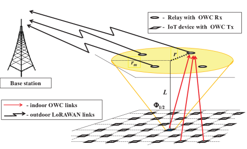
II-A The indoor OWC phase
In the first phase, the IoT devices perform data packet transmission via OWC transmitters, usually LED lamps operating in visible or IR spectrum. Data packets are sent in an uncoordinated fashion to DF-based relays placed on the ceiling of the indoor space. The intensity modulation with on-off keying is utilized in order to satisfy non-negative constraint. All relays contain the OWC receivers (photo detectors) where direct detection and optical-to-electrical signal conversion is performed.
Even though optical wireless links include both LoS and diffuse components, the reflected signals energy can be neglected since it is proved to be significantly lower than the energy of the LoS component [17]. Following the Lambertian law for modeling the optical LoS link, the intensity of the optical signal between the user and the relay is defined as [19, 20]
| (1) |
where the parameter denotes the field of view (FOV) of the receiver. We assume that the FOV of any of the OWC receivers is sufficiently large to detect the signal from any of the IoT devices, conditioned that the received power is sufficiently high. Parameters , and are the Euclidean distance between transmitter and receiver, the irradiance angle and the incidence angle, respectively. The physical surface area of the photodetector is denoted by , is the responsivity, and defines the gain of the optical filter. The optical concentrator is determined as , for , where represents the refractive index of lens at a photodetector. The OWC transmission follows a generalized Lambertian radiation pattern with the order as [19]
| (2) |
where represents the semi-angle at the half illuminance of LED, and defines the width of the optical beam. From Fig. 1 can be concluded that the semi-angle at the half illuminance of LED is related to the maximum radius of a LED lighting footprint, , as , where represents the distance between horizontal plane where users are located on the ceiling. With the assumption that the surface of OWC transmitters is parallel to the ceiling plane and there is no orientation of the OWC receivers, then , , , where represents the distance between relay and projection of the user position on the ceiling plane. The expression in (1) for the optical signal intensity can be rewritten as
| (3) |
where .
The user devices are randomly placed at the floor plane, while the relays are at fixed positions. If the positions of IoT devices are on the same plane and modeled by a uniform distribution, the probability density function (PDF) of the radial distance of a randomly placed user from a fixed receiver is [18]
| (4) |
After utilization of the technique for transformation of random variables, based on (3) and (4), the PDF of the optical signal intensity is expressed as [18]
| (5) |
where and . The instantaneous SNR of the VLC link can be defined as [19, 18]
| (6) |
where denotes the average transmitted optical power of a LED lamp, represents optical-to-electrical conversion efficiency, is noise spectral density and is the system bandwidth.
II-B The outdoor LoRaWAN phase
The second phase of two-tier random access scenario in Fig. 1 represents the RF uplink channel between relays and the base station. Upon correctly receiving the information data, each DF relay re-encodes and forwards data packets111SA approach and data recovery at relays and base station will be discussed in the next section.. It is assumed that no buffering is done at the relays, thus the packets are either sent to the base station in the subsequent time slot, or they are discarded, as we discuss later. Since the signal transmission is performed in the outdoor scenario, the SA-based LoRaWAN technology is adopted in this phase as a low power and licence-free transmission. The instantaneous SNR over RF link is defined as
| (10) |
where is the signal fading amplitude over RF link, represents an average transmitted power and is the the additive white Gaussian noise variance. The average SNR is defined as
| (11) |
We assume that each relay-to-base station RF channel follows independent and identical distributed (i.i.d.) Nakagami-m distribution, which is a general model suitable for both LoS and non-LoS transmissions [34]. The PDF and the CDF of the instantaneous SNR of each link are given respectively as [35]
| (12) |
| (13) |
where is the Nakagami-m fading parameter, and denotes the Incomplete Gamma function defined in [36, (8.350.2)].
III Throughput Performance Analysis
| name | symbol | value |
|---|---|---|
| Field of view (FOV) of the receiver | ||
| Photodetector surface area | cm2 | |
| Responsivity | A/W | |
| Optical filter gain | 1 | |
| Refractive index of lens at a photodetector | ||
| Optical-to-electrical conversion efficiency | ||
| Noise power spectral density | W/Hz | |
| System bandwidth | MHz |
As mentioned, the SA protocol is adopted as a medium access policy, with the assumption that the users are slot-synchronized. Transmission can start only at the beginning of time slots and one packet occupies exactly one slot. We name the average number of packets sent per slot as the channel load [pk/slot]. The number of users generating the data over a slot can be modeled by the binomial distribution, which can be well approximated with the Poisson distribution. Hence, we assume that the number of users generating the data over a slot are modeled a Poisson-distributed random variable with intensity as
| (14) |
Following a SA policy with assumption that there is no MPR capabilities and no capture effect at the relay, the data will be retrieved only if a single packet reaches the relay during a slot [16]. In other words, collisions are considered to be destructive, and the relay will recover the data only if one of the transmitted packets reaches the receiver.
In the user-to-relay transmission link, we adopt the model which assumes that the packet at the relay will be erased if the instantaneous SNR over VLC link, , defined in (6), is lower than previously determined threshold . In other words, the erasure event will happen if the total power contribution of received packet at the relay is lower than the power threshold which is in relation with . Thus, a packet at the relay is either in deep fade, i.e., erased, with probability , or it arrives unfaded with probability . Since the user-to-relay link represents the OWC channel (being characterized by the optical signal intensity defined in (1)), and the OWC users are randomly placed on the floor in the room, the probability is equal to the CDF defined in (9), i.e., . Hence, the successful reception of data conditioned on transmission occurs with probability
| (15) |
The average throughput experienced at each of the relays, in terms of average decoded packets per slot, can be determined after removing the conditioning as
| (16) |
which corresponds to the throughput of a SA link with erasures.
In next uplink LoRaWAN phase, relays contend to send the recovered data to the base station through a SA policy. We adopt the scheme proposed in [16] where, after decoding the successfully recovered packets, the relays independently determine if the packet will be forwarded. The probability if data will be transmitted further to the base station in the subsequent slot is denoted with , while holds for the probability that a data will be discarded. Similarly as in the OWC uplink, we assume that there are no MPR and no capture effect at the base station, thus the data will be correctly decoded if only a single packet reaches the base station during a slot. As it was mentioned in Section II, the RF channels between relays and base station are characterized as i.i.d. Nakagami-m fading links. The data packet at the base station will be erased with probability , which is in relation with the CDF defined in (13) as , where is previously determined threshold.
In order to derive the end-to-end throughput of the system under investigation, we follow the approach presented in [16]. We first we define the probability
| (17) |
which represents the overall probability that relay successfully decodes one of the packets sent by users, forwards it with probability , and the corresponding data is received unfaded at the base station. Information will be recovered only if a single packet is received at the base station unfaded, while the rest of them are erased. This is defined by the binomial probability conditioned on as
| (18) |
Finally, the end-to-end throughput for the system under investigation can then be determined by removing conditioning on as
| (19) |
Since the end-to-end throughput expression in (19) is presented in terms of infinite series, following the derivation presented in [16, Appendix A], the closed-form expression of end-to-end throughput is derived as [16]
| (20) |
where the ancillary function is defined as
| (21) |
Note that, although the structure of our and the system model proposed in [16] is the same, the results are different since we observe more general channel conditions compared to [16]. Also, unlike [16] which is inspired by satellite communications, this paper considers different technologies applied in the two phases of the uplink transmission.
IV Numerical Results
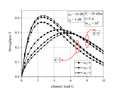
In this section, numerical results are presented which are obtained by using derived analytical expressions for the end-to-end throughput. Table I represents the values of the parameters assumed in this section [18, 37, 38]. It is assumed that the SNR thresholds are the same for both indoor and outdoor uplinks, i.e., . The probability that the data at the relay is directly forwarded to the base station is equal to .
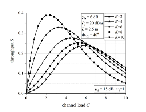
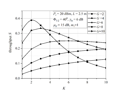
Fig. 2 depicts the end-to-end throughput dependence on the channel load, when different number of employed relays are considered. For lower channel load , greater number of relays leads to performance deterioration. This happens since we have fewer users, and employing more relays results in the situation when more packets will have power contribution higher than power threshold (resulting in collisions). Furthermore, the maximal value of the system throughput is observed for optimal value of channel load, . This optimal value is dependent on the number of active relays. When is higher, the optimal value is also higher, but the value of the maximal throughput is lower. After achieving its maximal value, the end-to-end throughput will be reduced with further increasing of . In this areas of intensive load, more users contend for the same number of relays, thus the probability that the collision will happen is increased.
Similarly, Fig. 3 presents how the increase in the number of relays affects the system throughput for different load conditions. For lower channel load, adding the relays will cause throughput performance improvement until some point. After this optimal number of relays, appending more relays will cause system performance impairment since most of them will overpower the threshold and there will be a lot of unfaded packets at the relays. The collisions will occur resulting in lower throughput. For higher , more users access the shared medium, thus greater number of relays reflects in the performance improving.
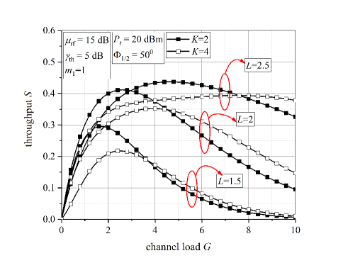
The end-to-end throughput dependence on the channel load for different room heights is presented in Fig. 4. The systems employing and are considered. The maximal values of throughput are also observed for different optimal values of channel load. With greater distance between planes where IoT users and relays are placed, the value of is higher. It can be concluded that the system throughput is greater with greater . The OWC channel conditions are more convenient for signal transmission when is smaller, since optical signal intensity (and received power) is stronger when optical signal propagates through shorter distances. Still, the system throughput for considered scenario is reduced with lower since a lot of packets will be received with enough power to overcome threshold, thus they will not be erased and collisions will occur.
Fig. 5 shows the end-to-end throughput versus channel load, considering different fading severity for RF channels. When system with relays is considered, it is noticed that lower , meaning that the fading is stronger, results in worse system performance. Since there are only two relays, at most two packets can be forwarded to the base station over a slot. The probability to have collided packets is small, since collision will occur when both relays recover a single packet over previous slot. In that case, fading has important role in determining the system throughput. With worsening RF channel conditions (lower ), throughput will be reduced since power of received power will be lower leading to the higher probability that the packet is erased. On the other hand, when , the inverse effect is noticed for lightly loaded conditions. Since now the most four packets can be transmitted to the base station from relays, stronger fading can reduce the power contributions of sent packets, resulting in the case that some of them can be erased, which will improve throughput. After achieving the maximal value, system throughput will be decreased. In this area, better RF channel conditions reflects in better throughput.
V Conclusion
In this work, we have presented a multireceiver SA based two-tier system. The first part of transmission is the indoor OWC uplink, where the IoT devices communicate with multiple relays by SA approach. The second phase refers to the LoRaWAN based on SA transmission in outdoor environment. The end-to-end throughput is determined based on the packet erasure probabilities, which are dependent on the OWC and RF channel conditions. Based on numerical results, it has been concluded that the increase of the number of implemented relays will not always be beneficial for system performance improvement. It is noted that the achieved throughput gain due to relays adding is in correlation with the channel load conditions, as well as highly dependent on the OWC and RF channel states.
Acknowledgment
This work has received funding from the European Union Horizon 2020 research and innovation programme under the WIDESPREAD grant agreement No 856697.
References
- [1]
- [2] F. Boccardi, R. W. Heath, A. Lozano, T. L. Marzetta, and P. Popovski, “Five disruptive technology directions for 5G,” IEEE Commun. Mag., vol. 52, no. 2, pp. 74–80, Feb. 2014.
- [3] F. Clazzer, A. Munari, G. Liva, F. Lazaro, C. Stefanovic, P. Popovski, ”From 5G to 6G: Has the time for modern random access come?” in Proc. 1st 6G summit, Levi, Finland, Mar. 2019. [Online]. Available: http://arxiv.org/abs/1903.03063.
- [4] N. Abramson, “The ALOHA system - Another alternative for computer communications,” in Proc. 1970 Fall Joint Computer Conference, vol. 37. AFIPS Press, 1970, pp. 281–285.
- [5] L. G. Roberts, “ALOHA packet system with and without slots and capture,” ACM SIGCOMM Computer Communication Review, vol. 5, no. 2, pp. 28–42, 1975.
- [6] N. Abramson, “The throughput of packet broadcasting channels,” IEEE Trans. Commun., vol. COM-25, no. 1, pp. 117-128, Jan. 1977.
- [7] LoRa Alliance, “The LoRa Alliance Wide Area Networks for Internet of Things,” www.lora-alliance.org.
- [8] Sigfox, “SIGFOX: The Global Communications Service Provider for the Internet of Things,” www.sigfox.com.
- [9] 3GPP TR 37.868 V11.0, Study on RAN improvments for machine-type communications, Oct. 2011.
- [10] M. Zorzi, ”Mobile radio slotted ALOHA with capture, diversity and retransmission control in the presence of shadowing,” Wireless Networks, vol. 4, no. 5, pp. 379-388, 1998.
- [11] M. S. Corson and A. Ephremides, “An analysis of multi-receiver, non- adaptive, slotted ALOHA with capture for wireless communications in factories,” in Proc. IEEE 12th Ann. Joint Conf. Comp. and Comm. Soc. (INFOCOM), San Francisco, CA, USA, Mar. 1993, pp. 421–428.
- [12] D. Jakovetic, D. Bajovic, D. Vukobratovic, and V. Crnojevic, “Cooperative slotted aloha for multi-base station systems,” IEEE Trans. Commun., vol. 63, no. 4, pp. 1443–1456, 2015.
- [13] A. Munari, F. Clazzer, and G. Liva, ”Multi-receiver Aloha systems - a survey and new results,” in Proc. 2015 IEEE International Conference on Communication Workshop (ICCW), London, 2015, pp. 2108-2114.
- [14] A. Munari, F. Clazzer, G. Liva, and M. Heindlmaier, “Multiple-relay slotted ALOHA: performance analysis and bounds,” 2019. [Online]. Available: http://arxiv.org/abs/1903.03420
- [15] A. Munari, M. Heindlmaier, G. Liva and M. Berioli, ”The throughput of slotted aloha with diversity,” in Proc. 2013 51st Annual Allerton Conference on Communication, Control, and Computing (Allerton), Monticello, IL, 2013, pp. 698-706.
- [16] A. Munari and F. Clazzer, “Modern random access for beyond-5G systems: a multiple-relay ALOHA perspective,” in Proc. the 3rd Balkan Conference on Communications and Networking (BalkanCom 2019), Skopje, North Macedonia, June 10-12, 2019.
- [17] T. Komine and M. Nakagawa, “Fundamental analysis for visible-light communication system using LED lights,” IEEE Trans. Consum. Electron., vol. 50, no. 1, pp. 100–107, Feb. 2004.
- [18] A. Gupta, N. Sharma, P. Garg, and M.–S. Alouini, ”Cascaded FSO-VLC communication system,” IEEE Wireless Commun. Lett., vol. 6, no. 6, pp. 810–813, Dec. 2017.
- [19] Z. Ghassemlooy, W. Popoola, and S. Rajbhandari, Optical Wireless Communications: System and Channel Modelling With MATLAB® . Boca Raton, FL, USA: CRC Press, 2013.
- [20] Z. Ghassemlooy, L. N. Alves, S. Zvanovec, and M. A. Khalighi, (Eds.). Visible Light Communications: Theory and Applications. Boca Raton, FL, USA: CRC Press, 2017.
- [21] S. R. Teli, S. Zvanovec, and Z. Ghassemlooy, “Optical internet of things within 5g: Applications and challenges,” in Proc. 2018 IEEE Int. Conf. on Internet of Things and Intelligence System (IOTAIS), pp. 40–45.
- [22] Chia-Wei Chen, et al. ”Visible light communications for the implementation of internet-of-things,” Optical Engineering, vol. 55, no. 6, 2016.
- [23] M. Haus, A. Y. Ding, Q. Wang, J. Toivonen, L. Tonetto, S. Tarkoma, and J. Ott, “Enhancing indoor IoT communication with visible light and ultrasound,” in Proc. 2019 IEEE Int. Conf. on Communications (ICC), pp. 1–6.
- [24] K. Warmerdam, A. Pandharipande and D. Caicedo, ”Connectivity in IoT indoor lighting systems with visible light communications,” in Proc. 2015 IEEE Online Conference on Green Communications (OnlineGreenComm), Piscataway, NJ, 2015, pp. 47-52.
- [25] M. W. Eltokhey, M. Khalighi, and Z. Ghassemlooy, ”Multiple access techniques for VLC in large space indoor Scenarios: A comparative study,” in Proc. 2019 15th International Conference on Telecommunications (ConTEL), Graz, Austria, 2019, pp. 1-6.
- [26] S. S. Bawazir, P. C. Sofotasios, S. Muhaidat, Y. Al-Hammadi, and G. K. Karagiannidis, “Multiple access for visible light communications: Research challenges and future trends,” IEEE Access, vol. 6, pp. 26 167– 26 174, 2018.
- [27] S. Feng, R. Zhang, W. Xu, and L. Hanzo, ”Multiple access design for ultra-dense VLC networks: orthogonal vs non-orthogonal,” IEEE Trans. Commun., vol. 67, no. 3, pp. 2218-2232, March 2019.
- [28] M. Erol-Kantarci, and M. Uysal. ”Multiple access in visible light communication networks,” in Optical Wireless Communications, pp. 451-461. Springer, Cham, 2016.
- [29] L. Zhao, X. Chi, and S. Yang, “Optimal aloha-like random access with heterogeneous qos guarantees for multi-packet reception aided visible light communications,” IEEE Trans. Wireless Commun., vol. 15, no. 11, pp. 7872–7884, 2016.
- [30] D. Vukobratovic and F. J. Escribano,”Adaptive multi-receiver coded slotted ALOHA for indoor optical wireless communications”, [Online]. Available: http://arxiv.org/abs/2002.10569.
- [31] M. Pasetti,, et al. ”On the use of LoRaWAN for the monitoring and control of distributed energy resources in a smart campus,” Applied Sciences, vol 10., no. 2, 2020.
- [32] W. Xu, J. Y. Kim, W. Huang, S. S. Kanhere, S. K. Jha and W. Hu, ”Measurement, characterization, and modeling of LoRa technology in multifloor buildings,” IEEE Internet of Things Journal, vol. 7, no. 1, pp. 298-310, Jan. 2020.
- [33] S. Borkotoky, U. Schilcher, and C. Bettstetter, ”Cooperative relaying in LoRa sensor networks,” arXiv preprint arXiv:1905.06020, 2019.
- [34] J. G. Andrews, T. Bai, M. N. Kulkarni, A. Alkhateeb, A. K. Gupta, and R. W. Heath, ”Modeling and analyzing millimeter wave cellular systems,” IEEE Trans. Commun., vol. 65, no. 1, pp. 403–430, Jan. 2017.
- [35] M. K. Simon and M.–S. Alouni, Digital Communication over Fading Channels. 2nd ed., New York, NY: John Wiley & Sons Inc., 2004.
- [36] I. S. Gradshteyn and I. M. Ryzhik, Table of Integrals, Series, and Products. 6th ed., New York: Academic, 2000.
- [37] H. Marshoud, P. C. Sofotasios, S. Muhaidat, G. K. Karagiannidis, and B. S. Sharif, ”On the performance of visible light communication systems with non-orthogonal multiple access,” IEEE Trans. Wireless Commun., vol. 16, no. 10, pp. 6350–6364, Oct. 2017.
- [38] L. Yin, W. O. Popoola, X. Wu, and H. Haas, ”Performance evaluation of non-orthogonal multiple access in visible light communication,” IEEE Trans. Commun., vol. 64, no. 12, pp. 5162–5175, Dec. 2016.