Electromagnetic Field Exposure Avoidance thanks to Non-Intended User Equipment and RIS
Abstract
On the one hand, there is a growing demand for high throughput which can be satisfied thanks to the deployment of new networks using massive multiple-input multiple-output (MIMO) and beamforming. On the other hand, in some countries or cities, there is a demand for arbitrarily low electromagnetic field exposure (EMFE) of people not concerned by the ongoing communication, which slows down the deployment of new networks. Recently, it has been proposed to take the opportunity, when designing the future 6th generation (6G), to offer, in addition to higher throughput, a new type of service: arbitrarily low EMFE. Recent works have shown that a reconfigurable intelligent surface (RIS), jointly optimized with the base station (BS) beamforming can improve the received throughput at the desired location whilst reducing EMFE everywhere. In this paper, we introduce a new concept of a non-intended user (NIU). An NIU is a user of the network who requests low EMFE when he/she is not downloading/uploading data. An NIU lets his/her device, called NIU equipment (NIUE), exchange some control signaling and pilots with the network, to help the network avoid exposing NIU to waves that are transporting data for another user of the network: the intended user (IU), whose device is called IU equipment (IUE). Specifically, we propose several new schemes to maximize the IU throughput under an EMFE constraint at the NIU (in practice, an interference constraint at the NIUE). Several propagation scenarios are investigated. Analytical and numerical results show that proper power allocation and beam optimization can remarkably boost the EMFE-constrained system’s performance with limited complexity and channel information.
Index Terms:
Reconfigurable intelligent surface (RIS), massive multiple-input-multiple-output (M-MIMO), electromagnetic field exposure (EMFE), beamforming, millimeter wave (mmWave).I Introduction
The 5th Generation (5G) and most likely coming 6th Generation (6G) use massive multiple input multiple output (MIMO) beamforming and millimeter wave (mmWave) [1] to boost the spectral efficiency and the energy efficiency of networks. However, in some countries or cities, due to a local and stronger concern regarding human exposure to electromagnetic field (EMF), the electromagnetic field exposure (EMFE) limits set by the local regulation can reach a very low level, sometimes ten times lower [2, Fig. 10] than the levels recommended by International Commission on non-ionizing radiation protection (ICNIRP) [3]. Such arbitrarily low levels slow down the deployment of new networks, as it has been observed as early as with 4th Generation (4G) [4]. For these reasons, in [5, 6], it has been proposed to take the opportunity when designing the new generation of networks, the future 6G, to offer a new type of service: arbitrarily low EMFE as a service.
To do so, [5, 6] proposes to use reconfigurable intelligent surfaces, to shape the radio propagation environment [7, 8]. RIS are new network nodes reflecting waves in the desired direction and can be seen as intelligent mirrors or passive relays [9]. In [2, 10, 11, 12], RIS-aided schemes have been proposed to reduce the self-EMFE of a customer to his/her own user equipment (UE) transmissions in the uplink (UL) direction. In [13, 14, 15, 16], RIS-aided downlink (DL) beamforming schemes have been proposed to confine the over-exposed area, due to the transmission of the base station (BS) in the DL direction, inside a predefined circle. To our best knowledge, up to now, no study has been performed about the full potential of an EMFE-constrained RIS-assisted system.
To our best knowledge, no study has been performed so far on an EMFE-constrained RIS-assisted system where the exposed person helps the network control his/her EMFE. In this paper, for the first time, we introduce the concept of non-intended user (NIU) who is a customer of a mobile network operator with no data needs at the considered moment. The device carried by a NIU is called non-intended user equipment (NIUE). Without data transmission, the NIUE agrees to let the network use some control signaling and pilot exchanges between itself and the network while limiting the EMFE at the NIU, by controlling the level of interference at the NIUE. In this work, we study how the NIUE and a RIS could help the BS maximize the throughput at the intended user equipment (IUE) whilst meeting an EMFE constraint at the NIU (or equivalently meeting an interference constrain at the NIUE).
In order to realize this purpose, we propose different methods to maximize the throughput of an intended user (IU) and at the same time meet an EMFE requirement (i.e. a threshold) at an NIU side (this EMFE being caused by the DL transmission between a BS and an IU), thanks to the help of the NIUE, the UE, and an RIS. Our contributions are as follows:
-
•
We first formulate a joint beamforming and transmit power optimization (JBPO) problem at the BS side, with the objective to provide the best data rate at the IU under the NIU EMFE constraint.
-
•
We then propose two schemes to solve the JBPO problem with different performance and different assumptions on channel state information (CSI) availability: alternating optimization (AO)-, and discrete Fourier transform (DFT)-based optimization. They are later combined with five power allocation methods between the direct path and the RIS-assisted path. Finally, we provide analytical insights on 1) performance upper bound with transmitting different codewords as well as 2) a simple power-filling rule with priority on the direct-link transmission.
-
•
Two propagation scenarios are investigated: 1) the NIUE is located on the direct propagation path between the BS and the IU, and 2) the NIUE is located out of this path alongside the IU.
The remainder of the paper is organized as follows. Section II introduces the system model and the problem formulation of JBPO. In Section II, the AO- and DFT-based optimization schemes are proposed and analyzed. Section IV presents simulation results to validate the performance of the proposed methods while Section V concludes the paper.
II System Model
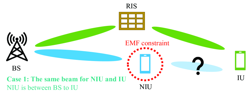
Consider an RIS-assisted MIMO DL system with one BS deployed with transmit antennas, one RIS with elements, and a pair of single-antenna IU and NIU. Here, IU is the user who wants to receive service from the BS while the NIU does not want to connect to the BS. More importantly, NIU prefers to have limited EMFE given that it requires no communication service. We assume that the NIU does not decode the message or absorb the energy from the BS and acts as one probe in space to detect the signal strength. Different from recent studies, e.g., [13, 11], as shown in Figs. 1-2, two cases are considered in this work:
-
•
Case 1: The NIU moves between the BS and the IU. Depending on the location of the NIU and the beam width from the BS, at some points/areas, the NIU and IU could receive the same transmission beam from the BS.
-
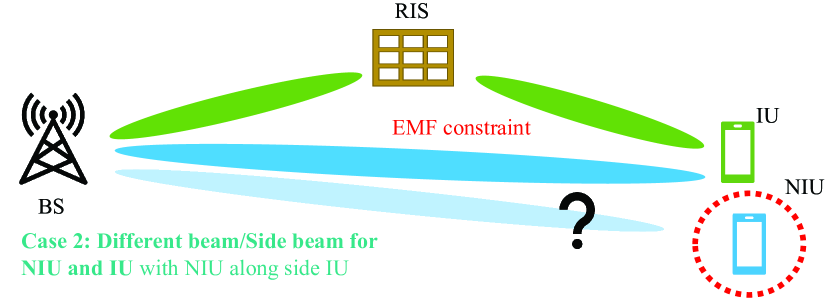
•
Case 2: The NIU moves alongside the IU and it could receive a different beam/side beam from the BS.
In this way, the received message for the IU is
| (1) |
where is the transmit power at the BS and is the transmitted message with a unit-power precoder. represents the additive Gaussian noise at the receiver side. The channel between BS-IU includes both the direct link (BS-IU) as well as the RIS-assisted link (BS-RIS-IU), i.e.,
| (2) |
Here, is the direct link, while and are the channel between BS-RIS and RIS-IU, respectively. We assume that is independent of and . Moreover,
| (3) |
is the reflection coefficient matrix of the RIS. Assuming the channels of BS-IU and BS-RIS-IU are spatially well separated/orthogonal such that the cross terms can be omitted, with BS-active and RIS-passive beamforming, the data rate at the IU can be expressed as 111Note that, by ignoring the cross terms we are actually presenting the lower bound of the system performance, whereas the exact performance with joint precoder design is left for further work.
| (4) |
where , , , are the power of the direct link, the power of the RIS link, the precoder of the direct link, and the precoder of the RIS link, respectively. Both and have unit power. Also, and represent the system bandwidth and the noise power spectral density, respectively.
Assuming the NIU occupies a unit area, the EMFE constraint in terms of received power can be written as [17]
| (5) |
with () being the transmit (receive) power of the BS-NIU link, and and are the channel and the precoder of the BS-NIU link, respectively. Both direct and reflected paths can be considered using such a model. We assume that the channel of the BS-NIU link is known at the BS, and the NIUE is capable of sensing the received power and reporting back to the BS.
III EMFE-aware Joint Beamforming and Transmit Power Optimization
The target of this work is to jointly maximize the rate at the IU with proper beamforming design (, , ) and power allocation (, ), in the presence of the NIU with an EMFE constraint. It can be mathematically stated as
| (6) | ||||
| s.t. | ||||
Here, is a constant which represents the EMFE constraint in terms of the received power at the NIU and can be modeled by, e.g., (5) as a function of . Since the beamforming optimization is independent of the transmit power, in the following, we first jointly optimize the beam of the BS and the RIS using two schemes with different CSI requirements. Then, we propose different methods to allocate the transmit power at the BS considering the EMFE requirement of NIU.
III-A Joint Beam Optimization for the BS and RIS
With the assumption of independent paths of the direct link and the RIS-assisted link, the beamforming pattern of the direct link can be obtained by, e.g., maximum-ratio transmission (MRT), as , with representing the Hermitian transpose.
For the RIS-aided indirect link, we need to jointly optimize the active beamforming vector at the BS, as well as the passive beamforming matrix at the RIS. This problem has been widely studied in the literature under different setups/assumptions. For instance, with perfect knowledge of CSI, i.e., and , AO has been shown to converge to the optimal solution of (6) [18, Sec. III-B] [19, Sec. III][20, Algorithm I]. In this work, we use AO in EMFE-aware RIS systems as an upper bound to compare to, as presented in Algorithm. 1. Here, maximizing is equivalent to optimize . Using AO, for a fixed , the optimal resulting in with . Then, for fixed , the optimal can be obtained by calculating the dominant right eigenvector of . Once the optimal beams of the BS and RIS are settled, various power allocation methods can be applied to reach the maximum rate (4), which are presented in Sec. III-B.
In some scenarios, especially with large number of RIS elements, optimizing and with explicit CSI may not be practical. Inspired by the precoding scheme designed in [21, Algorithm 1], we propose to use a DFT codebook-based beam optimization where the RIS beam is selected from the pre-defined beam patterns while only the concatenated channel is needed to optimize , as presented in Algorithm 2.
Complexity: The computational complexity of Algorithm. 1 is , where represents the number of iterations. For Algorithm. 2 the complexity is .
III-B Power Allocation Schemes for the Direct and RIS-assisted Links with EMFE Constraints
Depending on the channel condition as well as the EMFE constraint, the power division between the direct link and the RIS-aided link may vary. In this subsection, various power allocation methods with different performance-complexity trade-offs are presented. Specifically, we consider the following:
-
•
Method 1: All power is allocated to the BS-RIS-IU link, i.e., .
-
•
Method 2: All power is allocated to the direct link, i.e., .
-
•
Method 3: Based on the information from the NIU, i.e., in (5), the BS fills the direct link with and allocate the remaining power to .
- •
-
•
Method 5: As another upper bound of Method 3, we consider transmitting different codewords in the direct link and the RIS link, i.e., the IU rate can be upper bounded as
(8) This can be achieved by, e.g., spatial multi-stream with joint detection at the IU. In the following Lemma 1, we show that can be analytically determined when considering Method 5.
Lemma 1.
Define
| (9) |
and
| (10) |
as the average received signal-to-noise ratio (SNR) with optimized BS and RIS beamforming. The optimal power allocation can be calculated as
| (11) |
Proof.
The proof of Lemma 1 can be found in Appendix A. ∎
Lemma 1 is useful for evaluating the upper bounded performance in RIS-assisted networks with EMFE constraint. With the knowledge of optimized beam pattern leading to average received SNR, the optimal power allocation for the direct link and the RIS-assisted link can be analytically derived.
Lemma 2.
To obtain the best IU rate (6), the considered EMFE-constrained RIS system should always fill in the direct link with the maximum possible power if the direct link is better in the sense that .
Proof.
The proof of Lemma 2 can be found in Appendix B. ∎
IV Simulation Results
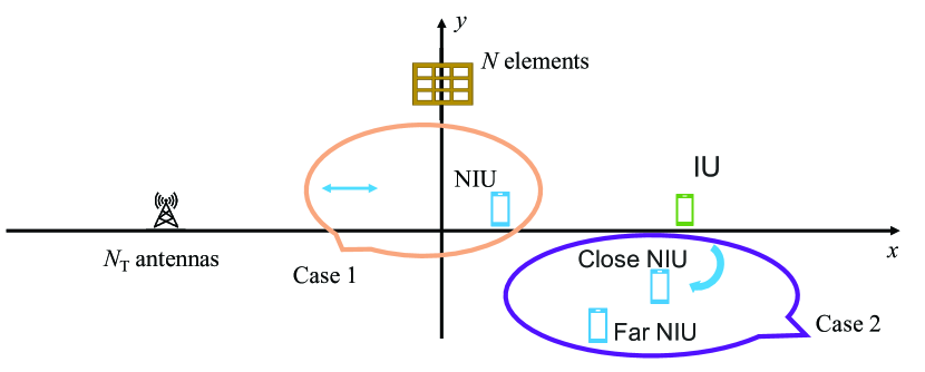
In this section, we present numerical results for the proposed EMFE-aware power allocation methods for RIS-assisted networks. The simulation setup is presented in Fig. 3. Consider one BS with antennas, one RIS with elements, one IU and one NIU both having one antenna. The carrier frequency is set to 28 GHz with 100 MHz channel bandwidth . The noise power is set as -174 dBm/Hz with 10 dB noise figure. The antenna gain of the BS, RIS, and the users are set to 18 dBi, 18 dBi, and 0 dBi, respectively. The total transmit power is 43 dBm in Fig. 4. As shown in Fig. 3, the BS is located at [-80m, 0] while the IU is fixed at [80m, 0] for Case 1 and [-70m, 0] for Case 2. Except for otherwise stated, the RIS is located at [0, 50m] for Case 1 and [-70m, 10m] for Case 2. Finally, for the NIU, it moves along the x-axis for the Case 1 (Fig. 1), while it stands close or far from the IU (Case 2, Fig. 2) with the same distance to the BS. For simplification, we omit the EMFE from the RIS-NIU link since the RIS beam is supposed to be optimized towards IU. Nevertheless, we verify this assumption in one of the curves in Fig. 4.
Our proposed methods are generic to different channel models. We assume that we have all line-of-sight (LoS) paths and the path loss at distance can be obtained by the mmMAGIC model [22, Table IV]
| (12) |
with 2 dB shadowing. Also, to fully evaluate the performance, for Case 1 (Fig. 1) we consider Rayleigh fading with a unit variance while Case 2 (Fig. 2) uses a more generic mmWave channel with angle-of-departure (AoD) and multipath:
| (13) |
Here, and is the number of paths (set to 3 in the simulation). Furthermore, is the antenna steering vector with and when is the wavelength. Moreover, the codebook-based beamforming proposed in Algorithm 2 can be applied with different codebooks. Here, we present results with [23]
| (14) |
where
| (15) |
| (16) |
and represents Kronecker product.
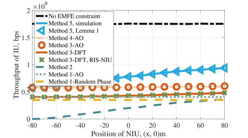
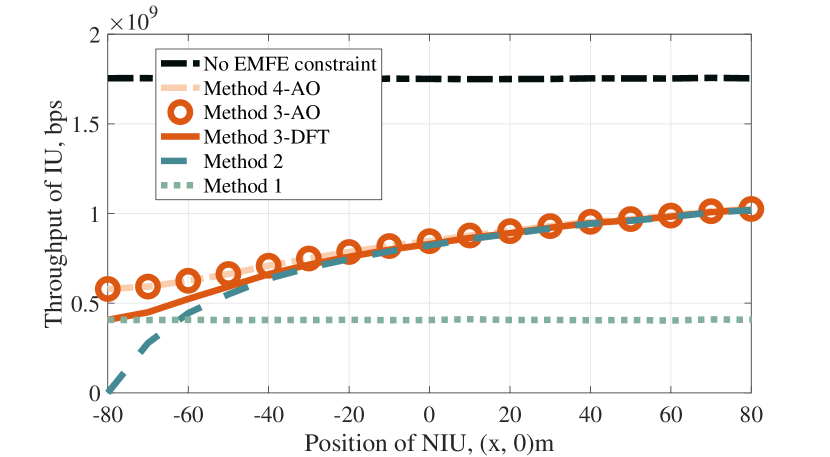
Figure 4 presents the IU throughput as a function of the position of NIU for Case 1, with the EMFE constraint is set to 0.005 mW. Here, we consider the cases with Method 1 (RIS only), Method 2 (direct link only), Method 3 with both AO and DFT-based beam optimization (corresponding to Algorithm 1 and 2, respectively), Method 4 with exhaustive power allocation using AO, Method 5 as an upper bound from both simulation and Lemma 1, and the case without EMFE constraint and transmit with the BS-IU direct link. The interference from RIS to NIU is considered in the case ”Method 3-DFT, RIS-NIU”. As an additional benchmark, the performance with random phase RIS is also presented. Then, in Fig. 5, with a more relaxed EMFE constraint ( 0.5 mW), we focus on the comparison of Methods 1-4 as well as AO and DFT-based beam optimization.
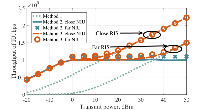
To study the performance of Case 2 where the NIU is alongside the IU, in Fig. 6, we plot the IU throughput versus the transmit power. Here, the EMFE constraint set to 0.1 mW and the AoD for the close and far NIU are set to and , respectively. We consider the cases with Method 1 (RIS only), Method 2 (direct link only), and Method 3 with DFT-based optimization (Algorithm 2). Finally, to evaluate the impact of the deployment of the RIS, both close and far RIS with respect to the IU are considered, and they have coordinates as (-70, 10)m, and (-30, 10)m, respectively.
According to these simulation results, the following conclusions can be drawn:
- •
-
•
For the considered two cases, i.e., the NIU between the BS and the IU (Case 1) and alongside the IU (Case 2), the system performance is affected by various parameters such as the strength of the EMFE constraint, the position of RIS, the total transmit power, as well as the relative distance between the NIU and IU.
-
•
With the EMFE constraint being considered, it is still beneficial to fully exploit the potential of the direct BS-IU path (which normally has better propagation conditions in terms of, e.g., path loss compared to the RIS path), with the help of NIU. As shown in a power-limited system in Figs. 4-5, the performance of only using the direct path increases with smaller EMFE constraints, i.e., further NIU. On the other hand, with an increased transmit power budget in Fig. 6, RIS-assisted link could eventually overperform even with a far-deployed RIS.
- •
- •
-
•
As can be seen in Figs. 4-5, the proposed DFT-based scheme (Algorithm. 2) could reach a close performance compared to the AO method, especially with a more relaxed EMFE constraint, and it does not require explicit CSI when optimizing the beams. Also, random phase RIS would result in a performance loss compared to AO.
V Conclusions
In this paper, we studied the EMFE-limited RIS-assisted system with two new types of constrained positions. Specifically, we reveal that with the help of NIUE detection, it is beneficial in terms of the system throughput to fully utilize the better propagation path, which is normally the direct BS-IU link. Also, we evaluated the system performance with the proposed AO- and DFT-based scheme with various power allocation methods. The DFT-based method is shown to be efficient with limited channel information. In addition, the analytical contributions on the upper bound of the system as well as the preference of the direction in power allocation provide solid insights on the considered setups.
Acknowledgement
This work was supported by the EU H2020 RISE-6G project under grant number 101017011.
Appendix A
With power allocation factor , the throughput of IU (• ‣ III-B) can be written as
| (17) |
Then, the derivative of with respect to is
| (18) |
Setting (Appendix A) equal to zero the optimal power allocation for the upper bounded IU rate (• ‣ III-B) can be obtained as 11.
Appendix B
(6) with power allocation factor can be simplified as
| (19) |
Its derivative with respect to is
| (20) |
When , i.e., the direct link is better, the derivative is always positive. As a result, the maximum allowed power () should be allocated to the direct path.
References
- [1] F. W. Vook, A. Ghosh, and T. A. Thomas, “MIMO and beamforming solutions for 5G technology,” in Proc. IEEE MTT-S International Microwave Symposium, Tampa, FL, USA, Jun. 2014, pp. 1–4.
- [2] L. Chiaraviglio, A. Elzanaty, and M.-S. Alouini, “Health risks associated with 5G exposure: A view from the communications engineering perspective,” IEEE Open J. Commun. Soc., vol. 2, pp. 2131–2179, Aug. 2021.
- [3] International Commission on Non-Ionizing Radiation Protection (ICNIRP), “For limiting exposure to electromagnetic fields (100 KHz to 300 GHz) ,” Health Phys, vol. 118, no. 5, pp. 483–524, Jun. 2020, [Online]. Available at: https://www.icnirp.org/cms/upload/publications/ICNIRPrfgdl2020.pdf.
- [4] Global System for Mobile Communications Association (GSMA), “Arbitrary Radio Frequency exposure limits: Impact on 4G network deployment. Case Studies: Brussels, Italy, Li thuania, Paris and Poland,” 2014, [Online]. Avaliable at: https://www.gsma.com/publicpolicy/wp-content/uploads/2014/03/Arbitrary-Radio-Frequencyexposure-limits_Impact-on-4G-networks-deployment_WEB.pdf.
- [5] E. C. Strinati et al., “Reconfigurable, intelligent, and sustainable wireless environments for 6G smart connectivity,” IEEE Commun. Mag., vol. 59, no. 10, pp. 99–105, Oct. 2021.
- [6] G. C. Alexandropoulos et al., “Smart wireless environments enabled by RISs: Deployment scenarios and two key challenges,” in 2022 Joint European Conference on Networks and Communications & 6G Summit (EuCNC/6G Summit), Grenoble, France, Jun. 2022, pp. 1–6.
- [7] M. D. Renzo et al., “Smart radio environments empowered by reconfigurable AI meta-surfaces: An idea whose time has come,” Eurasip J. Wirel. Commun. Netw., vol. 2019, no. 1, pp. 1–20, May 2019.
- [8] E. Basar, M. Di Renzo, J. De Rosny, M. Debbah, M.-S. Alouini, and R. Zhang, “Wireless communications through reconfigurable intelligent surfaces,” IEEE Access, vol. 7, pp. 116 753–116 773, Aug. 2019.
- [9] M. Di Renzo et al., “Reconfigurable intelligent surfaces vs. relaying: Differences, similarities, and performance comparison,” IEEE Open J. Commun. Soc., vol. 1, pp. 798–807, Jun. 2020.
- [10] H. Ibraiwish, A. Elzanaty, Y. H. Al-Badarneh, and M.-S. Alouini, “EMF-aware cellular networks in RIS-assisted environments,” IEEE Commun. Lett., vol. 26, no. 1, pp. 123–127, Jan. 2022.
- [11] A. Zappone and M. D. Renzo, “Energy efficiency optimization of reconfigurable intelligent surfaces with electromagnetic field exposure constraints,” IEEE Signal Process. Lett., vol. 29, pp. 1447–1451, Jun. 2022.
- [12] D.-T. Phan-Huy, Y. Bénédic, S. H. Gonzalez, and P. Ratajczak, “Creating and operating areas with reduced electromagnetic field exposure thanks to reconfigurable intelligent surfaces,” in Proc. IEEE SPAWC, Oulu, Finland, Jul. 2022, pp. 1–5, [Online]. Available at: https://arxiv.org/abs/2206.06880.
- [13] N. Awarkeh, D.-T. Phan-Huy, and R. Visoz, “Electro-magnetic field (EMF) aware beamforming assisted by reconfigurable intelligent surfaces,” in Proc. IEEE SPAWC, Lucca, Italy, Sept. 2021, pp. 541–545.
- [14] N. Awarkeh, D.-T. Phan-Huy, R. Visoz, and M. D. Renzo, “A novel RIS-aided EMF-aware beamforming using directional spreading, truncation and boosting,” in 2022 Joint European Conference on Networks and Communications & 6G Summit (EuCNC/6G Summit), Grenoble, France, Jun. 2022, pp. 7–12.
- [15] N. Awarkeh, D.-T. Phan-Huy, and M. D. Renzo, “A novel RIS-aided EMF exposure aware approach using an angularly equalized virtual propagation channel,” in 2022 Joint European Conference on Networks and Communications & 6G Summit (EuCNC/6G Summit), Grenoble, France, Jun. 2022, pp. 500–505.
- [16] Y. Yu, R. Ibrahim, and D.-T. Phan-Huy, “Dual gradient descent EMF-aware MU-MIMO beamforming in RIS-aided 6G networks,” in 2022 Workshop on Sustainable Wireless Networking (SWirNet), accepted, Turino, Italy, Sept. 2022.
- [17] L. Chiaraviglio, S. Turco, G. Bianchi, and N. Blefari-Melazzi, “Cellular network densification increases radio-frequency pollution: True or false?” IEEE Trans. Wireless Commun., vol. 21, no. 4, pp. 2608–2622, Apr. 2022.
- [18] Q. Wu and R. Zhang, “Intelligent reflecting surface enhanced wireless network via joint active and passive beamforming,” IEEE Trans. Wireless Commun., vol. 18, no. 11, pp. 5394–5409, Nov. 2019.
- [19] H. Guo, Y.-C. Liang, J. Chen, and E. G. Larsson, “Weighted sum-rate maximization for reconfigurable intelligent surface aided wireless networks,” IEEE Trans. Wireless Commun., vol. 19, no. 5, pp. 3064–3076, May 2020.
- [20] A. Zappone, M. Di Renzo, F. Shams, X. Qian, and M. Debbah, “Overhead-aware design of reconfigurable intelligent surfaces in smart radio environments,” IEEE Trans. on Wireless Commun., vol. 20, no. 1, pp. 126–141, Jan. 2021.
- [21] H. Huang, X. Wang, C. Zhang, K. Qiu, and Z. Han, “Reward-maximization-based passive beamforming for multi-RIS-aided multi-user MISO systems,” in Proc. IEEE GLOBECOM, Madrid, Spain, Dec. 2021, pp. 1–6.
- [22] T. S. Rappaport, Y. Xing, G. R. MacCartney, A. F. Molisch, E. Mellios, and J. Zhang, “Overview of millimeter wave communications for fifth-generation (5G) wireless networks—with a focus on propagation models,” IEEE Trans. Antennas Propag., vol. 65, no. 12, pp. 6213–6230, Dec. 2017.
- [23] Y. Han, S. Jin, J. Zhang, J. Zhang, and K.-K. Wong, “DFT-based hybrid beamforming multiuser systems: Rate analysis and beam selection,” IEEE J. Sel. Top. Signal Process., vol. 12, no. 3, pp. 514–528, Jun. 2018.