Broadband Bragg Phenomenon in a Uniform Medium
Abstract
A new mechanism of Bragg reflection is identified, one that, remarkably, occurs in a uniform medium and relies on resonant tuning of the medium’s parameters. Due to uniformity, reflection ensues over a broad wavelength range, much like a metal, but it is polarization dependent: one circular state is reflected, whilst the other is transmitted. Such a medium can thus provide a broadband, low-loss polarization divider/combiner. Assessment of the required parameters suggests that manufacturing is within range of current metamaterials technology. By externally regulating the medium’s parameters, a highly efficient optical modulator is possible with potential applications across optics, optoelectronics, and photonics.
Keywords Birefringence Broadband devices Circular Bragg phenomenon Metamaterials Negative refraction Optical activity Polarization selectivity
1 Introduction
Bragg reflection is said to occur when successive reflections of monochromatic light from a spatially modulated dielectric add up coherently. Such photonic structures are extensively used in optics, finding application, for example, in distributed feedback lasers [1], in wavelength division multiplexers (WDM) [2], or as dispersion cancellation filters in optical waveguides [3]. Fabrication of Bragg gratings [4, 5] is often challenging owing to the necessity of matching the scale of the medium’s variation to the wavelength of light, say on the order of microns or less. In this letter, we identify a fundamentally new mechanism to achieve Bragg-like reflection that, remarkably, is independent of matching the wavelength to a spatial period, and relies solely on resonant tuning of the medium’s parameters. The optical response is similar to the well-studied circular Bragg phenomenon (CBP) in structurally chiral media [6], whereby circularly polarized incident light that is co-handed with the medium’s helicity is reflected, whilst contra-handed light is transmitted. The CBP has been observed naturally in iridescent beetle shells [7], as well as in nano-fabricated sculptured thin films [8]. However, unlike the traditional CBP, in our identified mechanism there is no “Bragg wavelength” as such, and polarization selective response occurs over a broad wavelength band, limited only by material dispersion. Evaluating the parameters necessary to achieve such optical response, we confirm that practical realisations are indeed within reach of current metamaterials technology.
2 Combining birefringence with optical activity
For a birefringent and optically active reciprocal medium, the temporal frequency domain constitutive relations combine a dielectric tensor with the Drude-Born-Fedorov model [9]
| (1) |
where , are the fundamental electromagnetic fields, , are the excitation fields, , , and are the free-space permittivity, permeability, and impedance, respectively, and is the relative permeability. The chirality parameter measures the length, in wavelengths, that a linearly polarized wave propagates before its -vector rotates through . Defining the auxiliary fields , , and , the constitutive relations of Eq. (1) simplify to
| (2) |
This notation assures that all fields are similarly dimensioned, so that all the medium’s parameters are relative. We may now express the fields as and , with a unit vector in the direction of the wavevector being perpendicular to , and partition so that
| (3) |
where , , and . Then, for a monochromatic plane wave , combining the projections of Maxwell’s macroscopic source-free curl relations yields
| (4) |
where and in Cartesian coordinates is interpreted as . The free-space wavenumber is , where is the speed of light in vacuum, and the wavenumber in the medium is . In a propagation coordinate system () with transverse coordinates () chosen to diagonalize , as , the supported by the medium refractive indices , turn out to be
| (5) |
where is the average transverse dielectric constant and measures the birefringence.
3 Wavelength-independent Bragg zones
For an idealized lossless medium with real parameters, Eq. (5) shows that is purely imaginary whenever
| (6) |
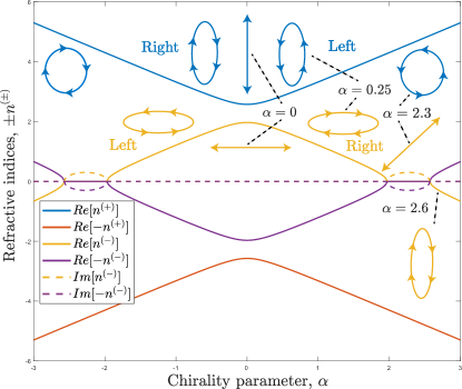
assuming ordering such that . Within these bands, centered at , one index is real and related to forward propagation, whilst the other is imaginary and related to evanescent waves. The sign of determines which is which: for , as illustrated in Fig. 1, is associated with a left-handed propagating eigenmode, while is associated with a right-handed eigenmode which becomes evanescent in the stopband region . In this band, the eigenmode corresponding to becomes linear, while the eigenmode corresponding to remains circular. Accordingly, for , as also depicted in Fig. 1, the emerging stopband refers to a left-handed linear eigenmode.
Both stopband edges signify extreme values of chirality, with being comparable to the average refractive index, . This resonance condition triggers the onset of negative refraction in a purely optically active medium [10, 11]. In fact, solving for optical activity, with a scalar , the characteristic eigenvalues are . For forward (backward) propagation, we must either choose or ( or ). Then, the corresponding eigenmodes describe, nominally, right- and left- handed spatial helices. For , the direction of phase advance and handedness of two of the modes are interchanged, but the Poynting vector does not change [12].
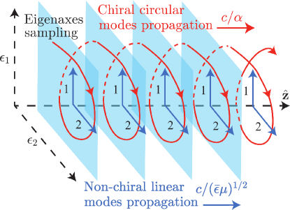
An intuitive picture of how such a stopband occurs is illustrated in Fig. 2. In the absence of optical activity (), the polarization eigenstates are linear and propagate with speeds , or on average . With optical activity present (, say), a circularly polarized wave propagating with speed will synchronously and alternately sample the co-propagating eigenaxes, provided that . For , the purely imaginary refractive index of the resonant polarization is , while the opposite-handed polarization, with refractive index , propagates too slowly to sample the alternation synchronously.
4 Coupled wave theory description of birefringent and optically active media
This interpretation is confirmed via coupled wave theory (CWT) [13]. To demonstrate this, we expand in terms of circularly polarized states, -left and -right, for which the forward and backward propagating electric field amplitudes are perturbed along the direction of propagation by the presence of birefringence, i.e.,
| (7) |
where
The relevant Helmholtz wave equation is found to be
| (8) |
Substituting Eq. (7) into Eq. (8), resolving along and , and phase-matching potentially synchronous terms, we obtain two systems of coupled wave equations, one for each polarization state, namely
| (9) |
with detuning parameters and coupling constant
| (10) |
respectively, where is the design wavelength. Crucially, on neglecting the dispersion of the average dielectric constant, the detuning parameters are wavelength-independent being solely determined by the medium’s parameters. The location of the resonances, each related to a specific polarization, can then be found by setting , leading to the regimes of Eq. (6).
When (), the () amplitudes remain constant, while the () evolve exactly as for a Bragg grating (see, e.g., [14]). Given a medium of length , these evolutions are described by the solutions to Eq. (9)
| (11) |
where
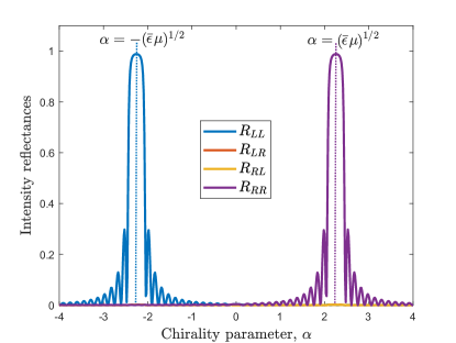
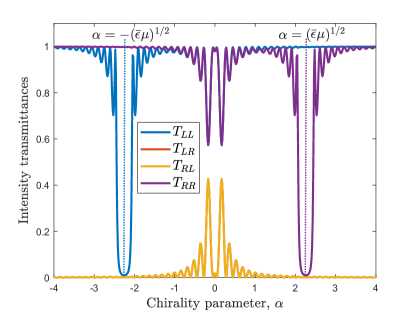
The optical response of a thin film of the considered medium to a normally incident plane wave may then be computed analytically (via the eigenmodes of Eq. (4) and field-matching at both interfaces of the film, noting the subtlety that for (), it is the eigenmode associated with () that carries energy away from the interface) or approximately (via CWT, as in [6]). The intensity reflectances and transmittances , where indicate reflection or transmission of the polarization for incident polarization, are demonstrated in Figs. 3 and 4, respectively. Bragg-like spectral features are evident at , whereby for broadband incident light of equal amounts of right and left circular polarizations (RCP and LCP), half is strongly reflected for one polarization, while the other half is transmitted for the orthogonal one. Therefore, the medium acts as a broadband polarization divider. For (), the range over which the fraction of reflected intensity into RCP (LCP) for incident RCP (LCP), (), is high (, say) is . Within this range, unit reflectance of incident RCP (LCP) results in the amplitudes of forward and backward RCP (LCP) light being equal within the medium, the superposition of these giving a net linear polarization. Indeed, for and just RCP light, combining Eq. (7) with Eq. (11) for , yields
| (12) |
Hence, the polarization is linear, which is logical as once exceeds , the wave is evanescent and must match the backward propagating reflected field.
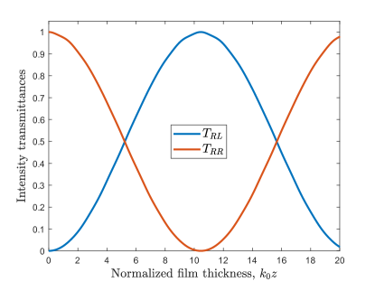
Interestingly, for , resolving along and , yet another pair of coupled wave equations emerges for the contra-handed forward (or backward) propagating waves. In terms of the circular components of the electric fields, and precisely at , both the exact and the CWT solutions agree to
| (13) |
This is a manifestation of the evolution of circularly polarized light in a linearly birefringent medium whereby and evolve, respectively, into and , being ‘unnaturally’ expanded on a circular basis. This continuous exchange of circular states between these transmissions with increasing film thickness is illustrated in Fig. 5. By contrast, Fig. 6 shows the characteristic Bragg-like evolution of into with increasing slab thickness, at , corroborating Eq. (11).

5 Material dispersion and practical realizations
The foundations of the proposed Bragg-like phenomenon lie in the stopbands occurring in the medium’s chirality domain dispersion, rather than that of wavelength. A natural question to address is whether considering material dispersion will affect the main features. Filling the medium under discussion with metallic spherical Mie resonators, uniformly distributed in space, as in [15], and assuming the relative permittivities to be equal and dispersive in both birefringent axes, the stopbands appear, shifted, as long as the electron density ,
| (14) |
where , are the electron mass and charge, respectively, refers to the design frequency, and to the operational half-bandwidth. If, for example, the design wavelength is µm, and the desired bandwidth µm, then by setting , the stopbands will be centred at with . Evidently, controlling via , provides a switching mechanism between resonant polarizations.
Although natural media that are simultaneously birefringent and optically active are known [16, 17], one with such extreme optical activity to satisfy is unlikely to be found in Nature. Turning to metamaterials, the giant optical rotatory power of , observed in [18], corresponds to a required refractive index of just at µm. Such extreme values have been observed in metamaterials at THz frequencies ( mm) with the remarkably high index of , achieving an optical rotatory power of in [11]. Recently, embedding a chiral medium into a non-chiral gold nanorod metamaterial, enhanced the circular dichroism [19]. Hence, the phenomena predicted here are within reach of a carefully designed meta-medium. To reduce the required optical activity we may lower the average refractive index. Actually, one of the founding meta-media consisted of orthogonal wire inclusions that present a lower effective refractive index through control of the plasma frequency [20, 21]. Utilizing wires of different diameters in the orthogonal directions will also provide the necessary birefringence.
6 Conclusion
Concluding, we have demonstrated that a uniform birefringent and optically active medium exhibits a broadband and polarization selective Bragg phenomenon, exclusively relying on matching the medium’s parameters rather than on wavelength matching. Current metamaterials technology provides the necessary parameters that are, moreover, in principle modulatable, leading to a very flexible broadband switch. Potential applications include: lasers (broadband, short-pulsed), optoelectronics (OLED displays, electron transport in organic semiconductors), waveguiding (add-drop WDM), or multi-use fiber sensors.
Acknowledgments
The authors acknowledge fruitful discussions with Dr. M. Foreman and Dr. K. Weir of Imperial College London.
References
- [1] H. Kogelnik and C. V. Shank. Coupled-wave theory of distributed feedback lasers. J. Appl. Phys., 43:2327–2335, 1972.
- [2] R. Zengerle and O. Leminger. Phase-shifted bragg-grating filters with improved transmission characteristics. J. Light. Technol., 13:2354–2358, 1995.
- [3] F. Ouellette. Dispersion cancellation using linearly chirped bragg grating filters in optical waveguides. Opt. Lett., 12:847–849, 1987.
- [4] K. O. Hill, B. Malo, F. Bilodeau, D. C. Johnson, and J. Albert. Bragg gratings fabricated in monomode photosensitive optical fiber by uv exposure through a phase mask. Appl. Phys. Lett, 62:1035–1037, 1993.
- [5] R. Kashyap. Fiber Bragg gratings. Academic press, 2nd ed. edition, 2010.
- [6] M. W. McCall. Simplified theory of axial propagation through structurally chiral media. J. Opt., 11:074006, 2009.
- [7] A. A. Michelson. On metallic colouring in birds and insects. Lond. Edinb. Dublin. Philos. Mag. J. Sci., 21:554–567, 1911.
- [8] A. Lakhtakia and R. Messier. Sculptured Thin Films: Nanoengineered Morphology and Optics. SPIE Optical Engineering Press, 2005.
- [9] C. F. Bohren. Introduction to complex mediums for optics and electromagnetics, volume 123. SPIE Optical Engineering Press, 2003.
- [10] S. Zhang, Y.-S. Park, J. Li, X. Lu, W. Zhang, and X. Zhang. Negative refractive index in chiral metamaterials. Phys. Rev. Lett., 102:023901, 2009.
- [11] M. Liu, E. Plum, H. Li, S. Li, Q. Xu, X. Zhang, C. Zhang, C. Zou, B. Jin, J. Han, and W. Zhang. Temperature-controlled optical activity and negative refractive index. Adv. Funct. Mater., 31:2010249, 2021.
- [12] M. W. McCall. What is negative refraction? J. Mod. Opt., 56:1727–1740, 2009.
- [13] A. Yariv and J. F. Lotspeich. Coupled-mode analysis of light propagation in optically active crystals. J. Opt. Soc. Am., 72:273–276, 1982.
- [14] M. W. McCall. On the application of coupled mode theory for modeling fiber Bragg gratings. J. Light. Technol., 18:236–242, 2000.
- [15] J. B. Pendry. A chiral route to negative refraction. Science, 306:1353–1355, 2004.
- [16] J. R. L. Moxon and A. R. Renshaw. The simultaneous measurement of optical activity and circular dichroism in birefringent linearly dichroic crystal sections. i. introduction and description of the method. J. Phys. Condens. Matter, 2:6807, 1990.
- [17] N. Ghosh, M. F. G. Wood, and I. Alex Vitkin. Mueller matrix decomposition for extraction of individual polarization parameters from complex turbid media exhibiting multiple scattering, optical activity, and linear birefringence. J. Biomed. Opt., 13:044036, 2008.
- [18] M. Kuwata-Gonokami, N. Saito, Y. Ino, M. Kauranen, K. Jefimovs, T. Vallius, J. Turunen, and Y. Svirko. Giant optical activity in quasi-two-dimensional planar nanostructures. Phys. Rev. Lett., 95:227401, 2005.
- [19] D. Vestler, I. Shishkin, E. A. Gurvitz, M. E. Nasir, A. Ben-Moshe, A. P. Slobozhanyuk, A. V. Krasavin, T. Levi-Belenkova, A. S. Shalin, P. Ginzburg, G. Markovich, and A. V. Zayats. Circular dichroism enhancement in plasmonic nanorod metamaterials. Opt. Express, 26:17841–17848, 2018.
- [20] W. Rotman. Plasma simulation by artificial dielectrics and parallel-plate media. IRE Trans. Antennas Propag., 10:82–95, 1962.
- [21] J. B. Pendry, A. J. Holden, W. J. Stewart, and I. Youngs. Extremely low frequency plasmons in metallic mesostructures. Phys. Rev. Lett., 76:4773–4776, 1996.