Coexistence of UAVs and Terrestrial Users in Millimeter-Wave Urban Networks
Abstract
5G millimeter-wave (mmWave) cellular networks are in the early phase of commercial deployments and present a unique opportunity for robust, high-data-rate communication to unmanned aerial vehicles (UAVs). A fundamental question is whether and how mmWave networks designed for terrestrial users should be modified to serve UAVs. The paper invokes realistic cell layouts, antenna patterns, and channel models trained from extensive ray tracing data to assess the performance of various network alternatives. Importantly, the study considers the addition of dedicated uptilted rooftop-mounted cells for aerial coverage, as well as novel spectrum sharing modes between terrestrial and aerial network operators. The effect of power control and of multiuser multiple-input multiple-output are also studied.
I Introduction
The interest is growing rapidly in unmanned aerial vehicles (UAVs) for applications such as monitoring, surveying, precision agriculture, construction, remote sensing, or product delivery [1, 2, 3, 4, 5]. Low-latency connectivity at high data rates is required for many of these applications and the millimeter wave (mmWave) frequency range offers bandwidths that can be instrumental to meet these requirements [6, 7, 8, 9, 10]. Also, links to UAVs are often line-of-sight (LOS), which is desirable due to the limited diffraction at these frequencies [11, 12].
There has been extensive work in UAV wireless communication and its interaction with cellular networks for frequencies below 6 GHz [13, 14, 15, 16, 17, 18]. Likewise, mmWave communication for terrestrial cellular networks has seen enormous progress [19, 20, 21], particularly with the development of the 3rd Generation Partnership Project (3GPP) 5G standard [22]. However, the coordination in the use of spectrum between aerial and terrestrial networks in the mmWave realm faces unique challenges. Chiefly, due to the directional nature of mmWave transmissions [23], the interference between aerial and terrestrial links is intricate, particularly in dense urban scenarios with substantial ground and building reflections.
In this paper, we investigate the coexistence of UAVs and terrestrial users (UEs) at mmWave frequencies under different spectrum sharing paradigms, thus bringing to the next level previous work that only focused on coverage [24]. To this end, we conduct extensive system-level simulations with 3GPP channel models and antenna patterns for terrestrial users [25, 26], and with data-driven aerial channel models along with realistic antenna patterns for UAVs [27].
We begin by considering a standard mmWave deployment, with a single operator providing connectivity to both UAVs and UEs, and investigate the UAV-UE interplay under single- (SU) and multiuser (MU) multiple-input multiple output (MIMO) operation. This first study shows that:
-
•
With SU-MIMO, UAV-to-UE interference is rather negligible because (i) urban LOS probability increases only marginally with the UAV height, (ii) the arrays of standard base stations (BSs) are downtilted, and (iii) highly directional mmWave transmissions provide considerable cell isolation.
-
•
With MU-MIMO, the data rates of both UAVs and UEs improve substantially as the interference remains low while multiple users are spatially multiplexed.
We further study a setup with two mobile network operators (MNOs) sharing the same spectrum: a terrestrial MNO running a standard mmWave network and an aerial MNO operating dedicated rooftop-mounted cells exclusively for UAVs. For this multi-MNO setup, we consider both closed access and open access paradigms, respectively confining UAVs to the aerial MNO and allowing UAVs to connect to whichever MNO offers the best service. This second study reveals that:
-
•
Ensuring UAV coverage under closed access requires high densities of dedicated cells, yet this does not significantly penalize UEs; the increased number of concurrent UAV interferers is balanced by the fact that UAVs can afford transmitting at lower power.
-
•
Under open access, dedicated cells are not crucial for coverage, but their addition improves the performance of both UEs and UAVs. Indeed, UEs can now access resources previously taken up by UAVs, and UAVs enjoy shorter links and better antenna gains.
II System Model
This work focuses on the uplink—the more data-hungry direction for UAVs—with the terrestrial UEs, UAVs, and BSs, all deployed in a area with wrap-around.
| Parameter | Value |
| Minimum UE-BS 2D distance () | |
| Minimum UAV-BS 3D distance () | |
| () | |
| Height of standard BSs () | |
| Height of dedicated BSs () | [10,30] |
| Bandwidth () | |
| Frequency () | |
| BS noise figure () | |
| UAV height () | |
| UAV and UE maximum transmit power () | |
| 3GPP vertical half-power beamwidth () | |
| 3GPP horizontal half-power beamwidth () | |
| Power control parameters, () and | -, |
| Number of associated users per cell |
II-A Deployment and Propagation Channel Features
Network Deployment
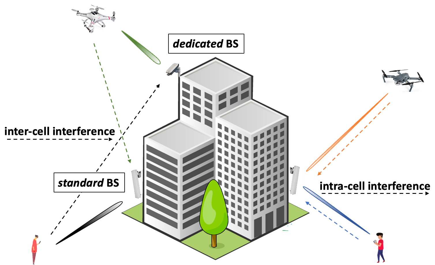
BSs are deployed following a homogeneous Poisson point process with a given average intersite distance (ISD), and they have three sectors, each corresponding to a cell and equipped with an uniform rectangular array (URA). Two types of BSs are considered: a standard deployment with antennas downtilted by , and a dedicated deployment with rooftop-mounted antennas uptilted by , as illustrated in Fig. 1. In turn, UAVs and terrestrial users feature URAs. Those mounted on UAVs are downtilted by while those at terrestrial UEs are distributed uniformly in azimuth with a fixed elevation of . All the parameters are summarized in Table I, following the simulation settings in [25]. The height of dedicated BSs, which is an additional parameter, is uniformly random between and m.
UAV Radiation Pattern
In order to incorporate the effects of the UAV frame on its radiation pattern, we simulated a quarter-wave monopole antenna (with bottom hemisphere coverage) placed under the UAV and used a software package [28] that utilizes geometrical optics, uniform theory of diffraction, and physical optics. Fig. 2 illustrates the effect of the UAV on the antenna radiation pattern. The fluctuations of the antenna gain are due to protruding parts of the UAV (e.g., landing skid, gimbal) that are within the field of view of the antenna [29]. Non-obviously, the effects of the UAV frame increase with the antenna directivity. We apply the obtained element radiation pattern to each UAV, whereas 3GPP antenna element patterns are adopted for BSs and UEs [26] .
Propagation Model
The 3GPP channel model reported in [25] is invoked to characterize the propagation between UEs and BSs (for urban microcells). To represent the mmWave propagation between UAVs and BSs, for which no calibrated model is available, the data-driven channel model developed in [27, 30] is invoked.

II-B Cell Selection and Beamforming
Each transmitter, UE or UAV, connects to the strongest BS. Both UAVs and UEs employ the open-loop power control policy specified in [31]. UAVs and UEs apply long-term transmit beamforming, aligning their beamforming vectors with the maximum-eigenvalue eigenvector of their channel covariance matrices [32]. After TX beamforming, we obtain a SIMO channel and signal to noise ration (SNR) from user and BS . With MU-MIMO, the minimum mean-square error (MMSE) receive vector for user at BS is given by [33]
| (1) |
where the summation is only active users scheduled in a particular time slot. The out-of-cell interference is represented with the sum over where is the number of active users in cell . As the channel matrices for other-cell users are not estimated by BS , their interference is regarded as spatially white. Accordingly, the overall gain from user to BS is
| (2) |
The interference experienced by user is then
| (3) |
where is the transmit power of user in cell , and are the transmit and receive antenna element gains on path , and is the pathloss along path between user and BS . Similarly, the received power from user is
| (4) |
Altogether, the SINR between UE and BS equals
| (5) |
where is the noise power spectral density and the bandwidth.
III UAV-UE Spectrum Sharing with
Standard mmWave Cells
We begin by considering a standard mmWave deployment. This is handled by a single terrestrial MNO that provides connectivity to both UAVs and terrestrial UEs. For this setup, we investigate the coexistence and interplay between the two populations of users under SU-MIMO and MU-MIMO. At this stage, no dedicated BSs are assumed.
III-A SU-MIMO mmWave Communication
To evaluate the amount of interference introduced by UAVs depending on their penetration rate and power control, we examine the three configurations reported in Table II, namely with (1) no UAVs in the network, (2) a fraction of 50% of UAVs employing fractional power control, and (3) a fraction of 50% UAVs transmitting at maximum power. Since the network operates in SU-MIMO mode, each BS schedules a single user at random on a given time-frequency physical resource block. In configurations (2) and (3), half of the scheduled users on average are UAVs.
| Configuration | UAV fraction | UAV power control |
| None | ||
| Open loop | ||
| Max ( dBm) |
Fig. 3 shows the distribution of SINR and interference-to-noise ratio (INR) for UEs. Under SU-MIMO, the interference observed is only of intercell origin. The low INR values suggest that the network is predominantly noise-limited and that, as a consequence, UAV power control improves the SINR of UEs by only 1-2 dB relative to full-power transmission (config 2 vs. config 3). The reasons why the interference generated by UAVs onto UEs is rather negligible at mmWave frequencies are as follows:
-
•
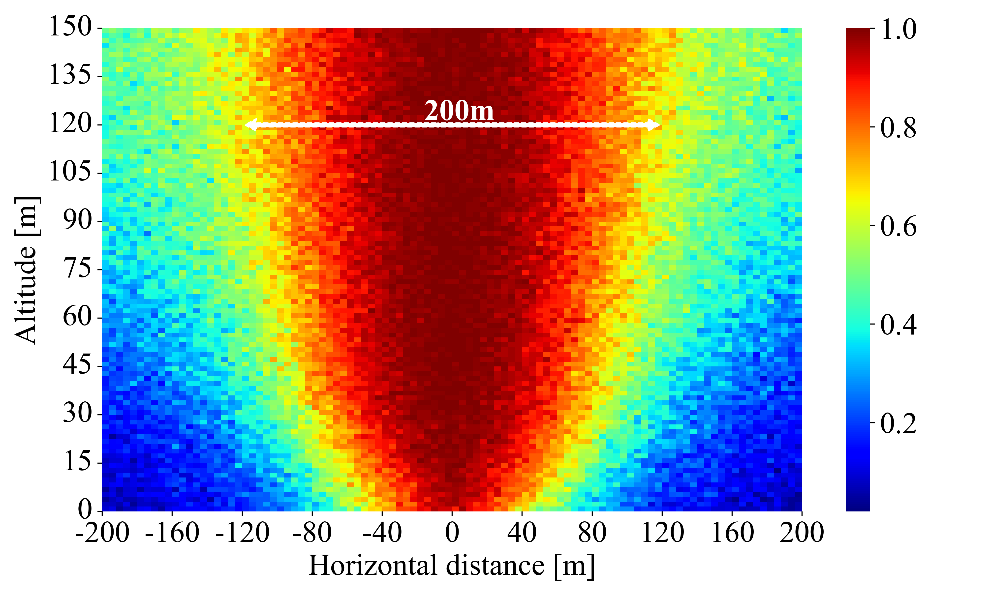
LOS probability in urban scenarios increases only marginally with the UAV altitude. Fig. 4 shows the LOS probability of the aerial channel model developed in [27]. Since UAVs are surrounded by buildings, the BS is highly visible by UAVs flying at m only within a horizontal distance of m. Hence, the chance to cause severe interference to UEs is low.
-
•
The arrays of standard BSs are downtilted by , mitigating the interference from UAVs due to the reduced antenna element gains.
-
•
Lastly, the increased pathloss and highly directional transmissions at mmWave frequencies result in a considerable attenuation of the interference.

III-B MU-MIMO mmWave Communication
There is a limited amount of prior work on exploiting MU-MIMO in mmWave networks [34, 35, 36]. In particular, there is no established research on spectrum sharing between UEs and UAVs with MU-MIMO. In this section, we tackle this issue by presenting the distribution of achievable data rates with an increasing number of simultaneous scheduled users. We consider associated users per cell, connected through the control channel but not necessarily scheduled in a particular time slot. In each time slot, the BS schedules users and hence each user is scheduled in a fraction of the time slots. We simulated a scenario with UAVs and UEs per BS, so the average value of . When scheduled, all users obtain access to the full bandwidth resulting in an average rate
| (6) |
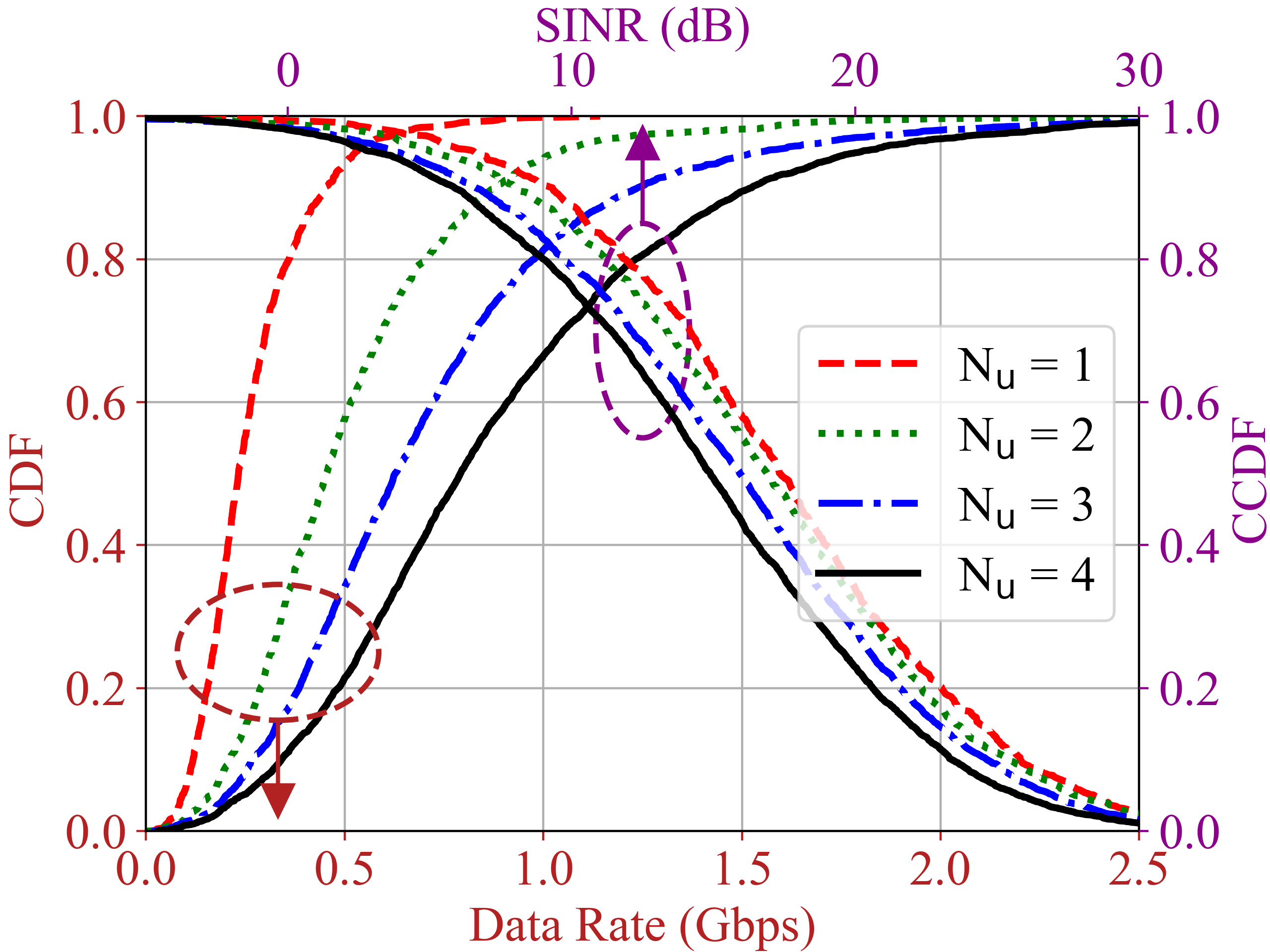
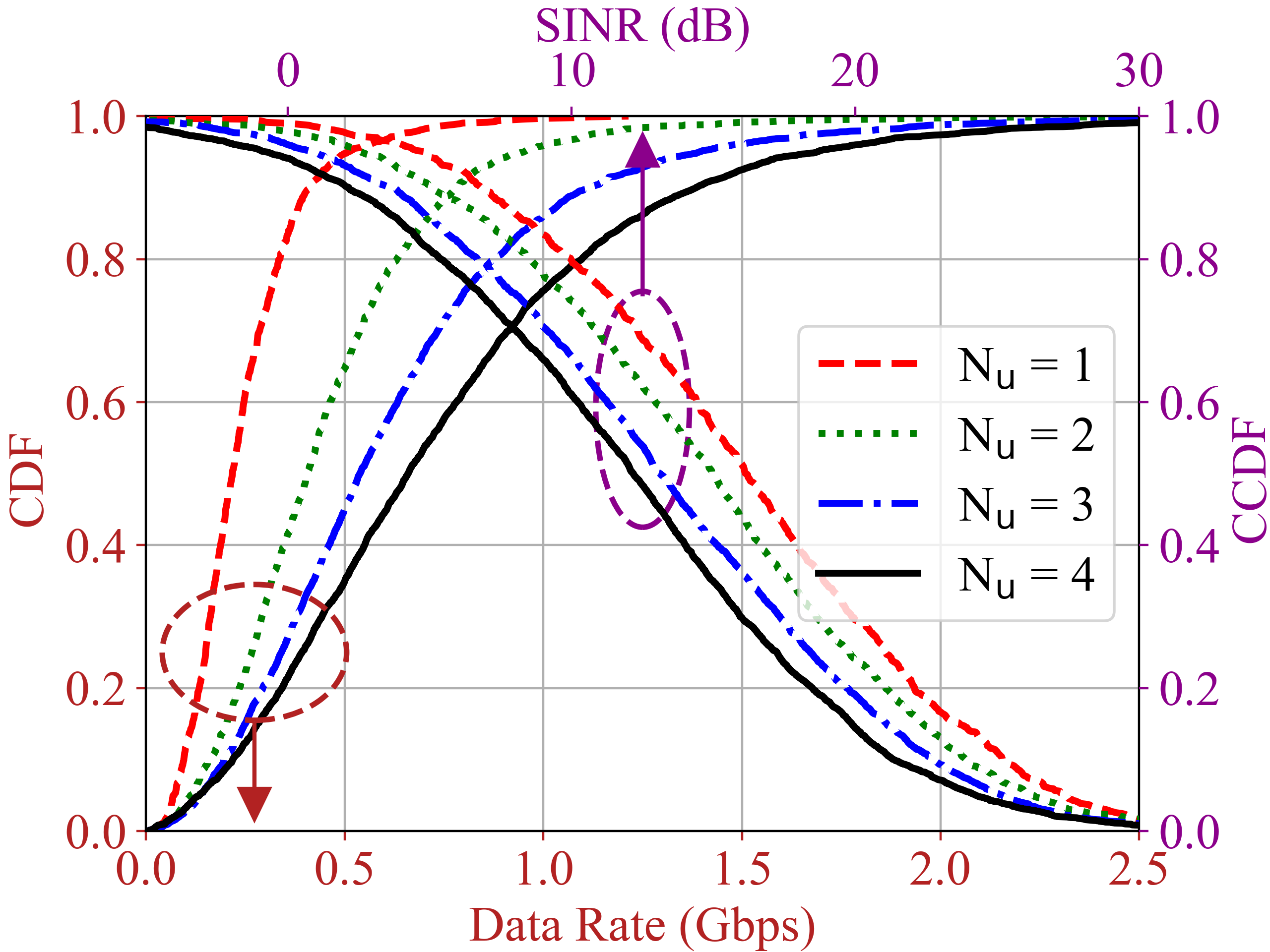
Fig. 5 shows the data rate and SINR distributions of UAVs and terrestrial UEs with increasing active users. Due to MU-MIMO, the achievable data rate of both UAVs and UEs improves substantially. Although the number of scheduled users increases, the interference is still minimal. As shown in Fig. 5, the SINR coverage for UEs and UAVs is still ensured with a higher number of scheduled users ().
IV UAV-UE Spectrum Sharing with
Dedicated Aerial mmWave Cells
| Single MNO | Multi MNO — Closed Access | Multi MNO — Open Access | |
| Spectrum reuse and efficiency | Low: No dedicated deployment; no spectrum reuse between aerial and terrestrial networks. | Medium: Suboptimal spectrum and infrastructure reuse due to restricted association and lack of synchronization. | High: Optimal spectrum and infrastructure reuse; seamless interference and user association coordination. |
| Coordination for resource allocation | None: Single operator running autonomously, no need for coordination. | Low: Requires monitoring inter-operator interference but scheduling, beamforming, and networking decisions are made individually. | High: Requires operators to manage aerial and terrestrial users jointly. |
In this section, we consider a hypothetical setup with MNOs operating in the same frequency band, namely:
-
•
A terrestrial operator, MNO, running a standard mmWave network as described in Section III.
-
•
An aerial operator, MNO, running a dedicated mmWave network consisting of rooftop-mounted, uptilted BSs that are reserved exclusively for UAV communication.
As the penetration of UAVs increases, terrestrial MNO may choose to share—under some leasing agreement—their spectrum with another MNO that only intends to provide aerial connectivity, giving rise to the above multi-MNO scenario [18]. For this scenario, we examine the performance of both UAVs and UEs under two spectrum sharing paradigms:
-
•
Closed access, where UAVs are only allowed to connect to dedicated BSs. On one hand, this paradigm requires low-to-no coordination for radio resource allocation, since all scheduling, beamforming, and networking decisions are performed individually by each MNO. On the other hand, such simplification comes at the cost of a suboptimal spectrum usage, owing to the restricted UAV association and lack of synchronization.
-
•
Open access, with UAVs allowed to connect to whichever BS offers the best quality of service, standard or dedicated. This enables a more efficient use of spectrum and network infrastructure. However, a high coordination between the MNOs is required to jointly manage radio resources for aerial and terrestrial users, possibly entailing MNO and MNO to belong to the same network provider.
Fig. 6 further summarizes the main features of the two multi-MNO spectrum sharing paradigms as compared to a single-MNO scenario. In the remainder of this section, we present the performance results obtained under the closed access and open access paradigms. We consider different dedicated BS densities by varying ISDd, and consider MU-MIMO with .
Fig. 8 shows the SINRs and data rates attained by UAVs and UEs under closed access, for various values of the dedicated BSs ISD. Since UAVs can only connect to dedicated BSs, the density of the latter greatly affects UAV coverage, with an ISD of 200 m or less required to keep the UAV outage at bay. As the density of dedicated BSs decreases, so does the number of concurrent UAV interferers seen by each standard BS. However, sparser dedicated deployments occasionally force UAVs to connect to far-flung dedicated BSs, thereby increasing their transmission power and generating stronger interference to standard BSs, an instance of the near-far problem. Overall, these two phenomena largely cancel one another, and the data rate experienced by UEs only marginally shrinks with the dedicated BS density.
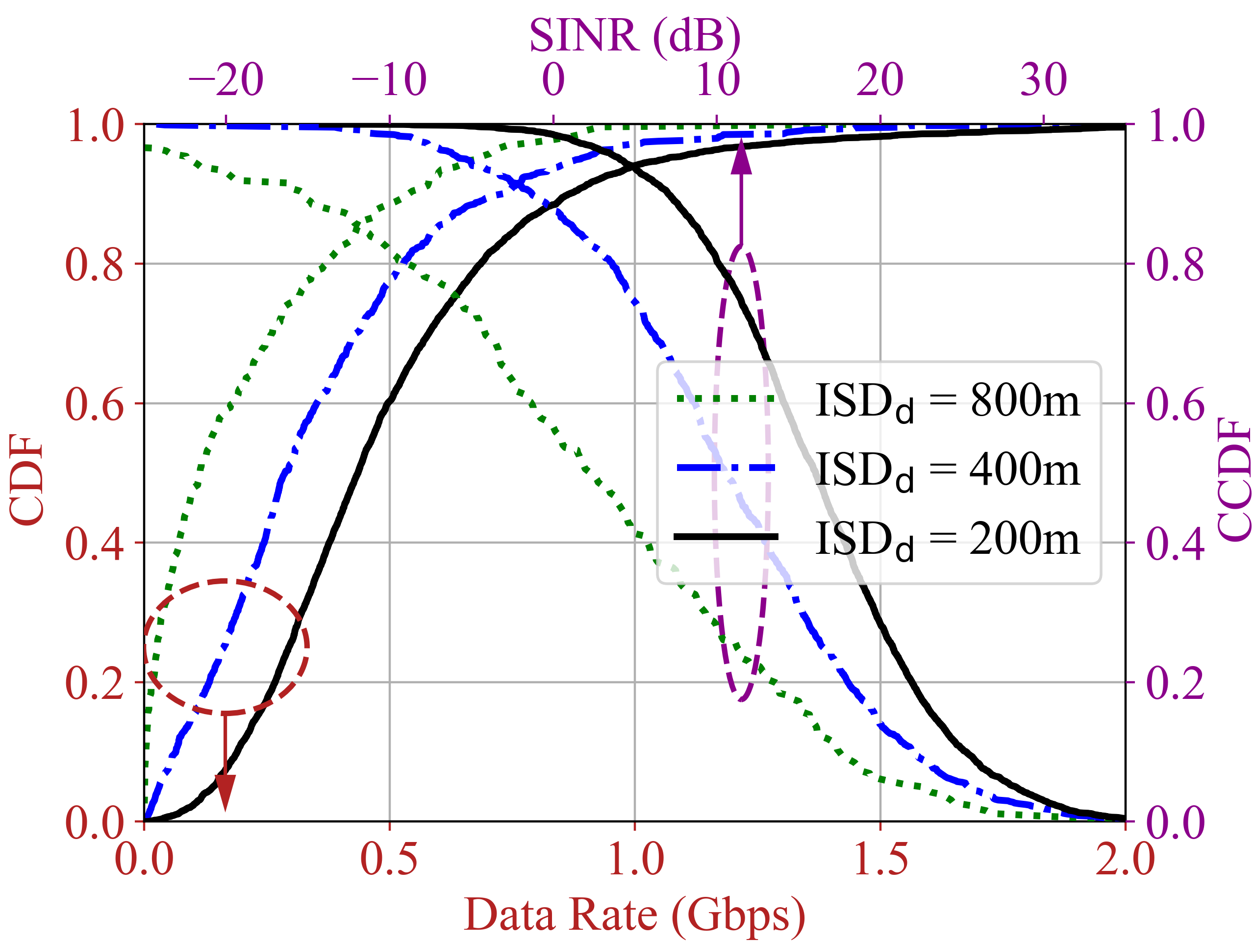

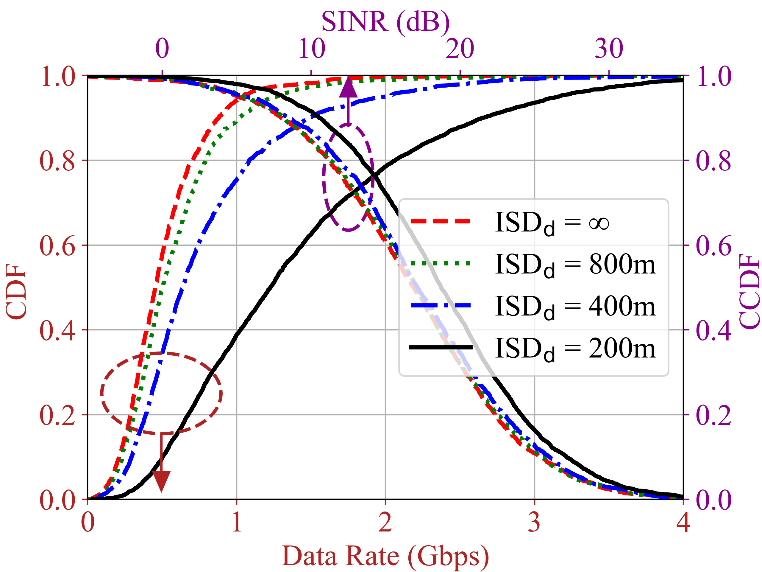
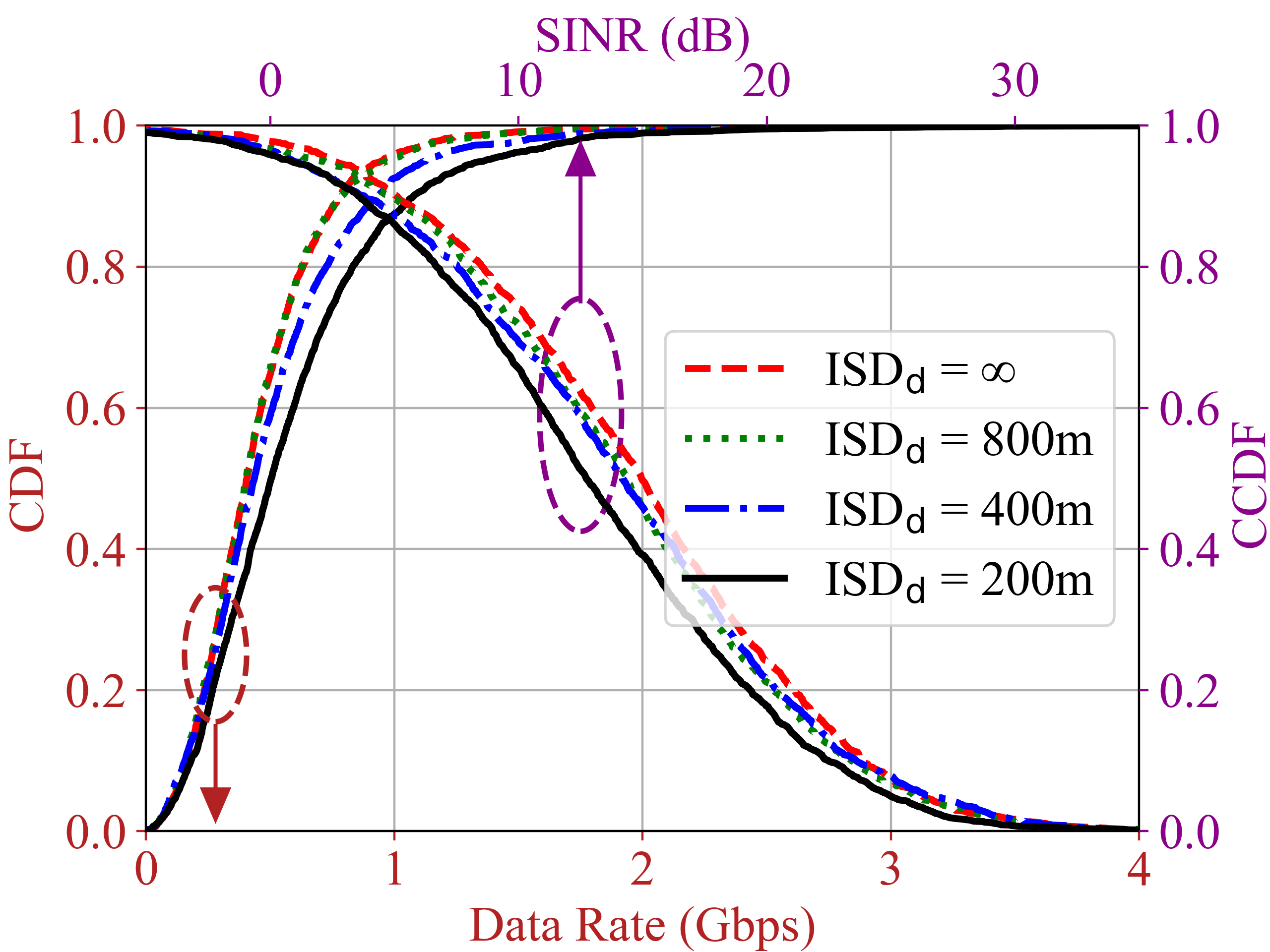
Fig. 8 shows the SINRs and data rates achieved by UAVs and UEs under open access, with UAVs allowed to connect to the BS providing the highest signal strength, thereby circumventing the near-far effect. The figure considers three values for the dedicated BSs ISD, as well as the baseline case without dedicated deployment, labeled as ISD. Despite introducing additional interference on the UEs—see SINR curves in Fig. 8(b)—, an increase in the number of dedicated BSs ultimately improves the data rates for both UEs and UAVs. Indeed, UEs can now access resources that were previously taken up by UAVs, as many of the latter are offloaded to dedicated BSs. In turn, UAVs achieve higher data rates because, when connecting to dedicated BSs, the link distance is reduced, uptilted arrays provide higher element gains, and resources are not shared with UEs.
V Conclusion
The goal of this paper was to understand the effect of mmWave spectrum sharing among UAVs and terrestrial users. To this end, an extensive campaign of simulations was launched, incorporating an accurate directional mmWave aerial channel model and UAV antenna patterns alongside 3GPP-based terrestrial mmWave channels and BS antenna patterns.
We considered multiple scenarios: (i) one with a single terrestrial operator running a standard mmWave network with SU-MIMO and MU-MIMO, (ii) another where a second aerial operator reuses the same spectrum independently to support UAVs via dedicated uptilted cells, (iii) and one last scenario where the two operators jointly offer connectivity to UAVs. Multiple insights have been drawn:
-
•
The interference generated by UAVs onto terrestrial UEs in standard mmWave networks is minimal, thanks to downtilted cells and high directionality.
-
•
Owing to the above intrinsic spatial separation, MU-MIMO is highly effective and data rates improve despite the additional concurrent interferers.
-
•
Co-channel uptilted BSs run independently by an aerial operator in closed access mode can provide satisfactory UAV coverage, provided they are densely deployed.
-
•
In open access—where UAVs can connect to either standard or dedicated uptilted cells—such uptilted cells are no longer crucial for UAV coverage, but their addition boosts the data rates of UAVs and UEs alike.
References
- [1] G. Geraci, A. Garcia-Rodriguez, M. M. Azari, A. Lozano, M. Mezzavilla, S. Chatzinotas, Y. Chen, S. Rangan, and M. Di Renzo, “What will the future of UAV cellular communications be? A flight from 5G to 6G,” IEEE Communications Surveys & Tutorials, pp. 1–1, 2022.
- [2] Y. Zeng, I. Guvenc, R. Zhang, G. Geraci, and D. W. Matolak (Eds.), UAV Communications for 5G and Beyond. Wiley – IEEE Press, 2020.
- [3] W. Saad, M. Bennis, M. Mozaffari, and X. Lin, Wireless Communications and Networking for Unmanned Aerial Vehicles. Cambridge University Press, 2020.
- [4] Y. Zeng, Q. Wu, and R. Zhang, “Accessing from the sky: A tutorial on UAV communications for 5G and beyond,” Proceedings of the IEEE, vol. 107, no. 12, pp. 2327–2375, 2019.
- [5] N. Cherif, W. Jaafar, H. Yanikomeroglu, and A. Yongacoglu, “3D aerial highway: The key enabler of the retail industry transformation,” IEEE Communications Magazine, vol. 59, no. 9, pp. 65–71, 2020.
- [6] Z. Xiao, P. Xia, and X.-G. Xia, “Enabling UAV cellular with millimeter-wave communication: Potentials and approaches,” IEEE Communications Magazine, vol. 54, no. 5, pp. 66–73, 2016.
- [7] C. Zhang, W. Zhang, W. Wang, L. Yang, and W. Zhang, “Research challenges and opportunities of UAV millimeter-wave communications,” IEEE Wireless Communications, vol. 26, no. 1, pp. 58–62, 2019.
- [8] M. Mozaffari, W. Saad, M. Bennis, and M. Debbah, “Communications and control for wireless drone-based antenna array,” IEEE Transactions on Communications, vol. 67, no. 1, pp. 820–834, Jan 2019.
- [9] J. Lee et al., “Spectrum for 5G: Global status, challenges, and enabling technologies,” IEEE Communications Magazine, vol. 56, no. 3, pp. 12–18, 2018.
- [10] M. Shafi, A. F. Molisch, P. J. Smith, T. Haustein, P. Zhu, P. De Silva, F. Tufvesson, A. Benjebbour, and G. Wunder, “5G: A tutorial overview of standards, trials, challenges, deployment, and practice,” IEEE Journal on Selected Areas in Communications, vol. 35, no. 6, pp. 1201–1221, 2017.
- [11] W. Khawaja, O. Ozdemir, and I. Guvenc, “UAV air-to-ground channel characterization for mmWave systems,” in Proc. IEEE VTC-Fall, 2017.
- [12] K. Heimann, J. Tiemann, S. Boecker, and C. Wietfeld, “On the potential of 5G mmWave pencil beam antennas for UAV communications: An experimental evaluation,” in Proc. ITG WSA, March 2018, pp. 1–6.
- [13] G. Geraci, A. Garcia Rodriguez, L. Galati Giordano, D. López-Pérez, and E. Björnson, “Understanding UAV cellular communications: From existing networks to massive MIMO,” IEEE Access, vol. 6, pp. 67 853–67 865, Nov. 2018.
- [14] X. Lin, V. Yajnanarayana, S. D. Muruganathan, S. Gao, H. Asplund, H.-L. Maattanen, M. Bergstrom, S. Euler, and Y.-P. E. Wang, “The sky is not the limit: LTE for unmanned aerial vehicles,” IEEE Communications Magazine, vol. 56, no. 4, pp. 204–210, 2018.
- [15] M. M. U. Chowdhury, I. Guvenc, W. Saad, and A. Bhuyan, “Ensuring reliable connectivity to cellular-connected UAVs with uptilted antennas and interference coordination,” arXiv:2108.05090, 2021.
- [16] A. Garcia-Rodriguez, G. Geraci, D. López-Pérez, L. Galati Giordano, M. Ding, and E. Björnson, “The essential guide to realizing 5G-connected UAVs with massive MIMO,” IEEE Communications Magazine, vol. 57, no. 12, pp. 84–90, Dec. 2019.
- [17] M. Benzaghta, G. Geraci, R. Nikbakht, and D. López-Pérez, “UAV communications in integrated terrestrial and non-terrestrial networks,” in Proc. IEEE Globecom, 2022.
- [18] G. Geraci, D. López-Pérez, M. Benzaghta, and S. Chatzinotas, “Integrating terrestrial and non-terrestrial networks: 3D opportunities and challenges,” arXiv:2207.10385, 2022.
- [19] S. Rangan, T. S. Rappaport, and E. Erkip, “Millimeter-wave cellular wireless networks: Potentials and challenges,” Proceedings of the IEEE, vol. 102, no. 3, pp. 366–385, March 2014.
- [20] T. S. Rappaport et al., “Millimeter wave mobile communications for 5G cellular: It will work!” IEEE Access, vol. 1, pp. 335–349, May 2013.
- [21] M. Agiwal, A. Roy, and N. Saxena, “Next generation 5G wireless networks: A comprehensive survey,” IEEE Communications Surveys & Tutorials, vol. 18, no. 3, pp. 1617–1655, 2016.
- [22] J. Andrews, S. Buzzi, W. Choi, S. Hanly, A. Lozano, A. Soong, and J. Zhang, “What will 5G be?” IEEE Journal on Selected Areas in Communications, vol. 32, no. 6, pp. 1065–1082, 2014.
- [23] W. Roh, J.-Y. Seol, J. Park, B. Lee, J. Lee, Y. Kim, J. Cho, K. Cheun, and F. Aryanfar, “Millimeter-wave beamforming as an enabling technology for 5G cellular communications: Theoretical feasibility and prototype results,” IEEE Communications Magazine, vol. 52, no. 2, pp. 106–113, 2014.
- [24] S. Kang, M. Mezzavilla, A. Lozano, G. Geraci, W. Xia, S. Rangan, V. Semkin, and G. Loianno, “Millimeter-wave UAV coverage in urban environments,” in Proc. IEEE Globecom, 2021, pp. 1–6.
- [25] 3GPP TR 38.901, “Study on channel model for frequencies from 0.5 to 100 GHz (Release 16),” Dec. 2019.
- [26] 3GPP TR 37.840, “Study of radio frequency (RF) and electromagnetic compatibility (EMC) requirements for active antenna array system (AAS) base station (Release 12),” Dec. 2013.
- [27] W. Xia, S. Rangan, M. Mezzavilla, A. Lozano, G. Geraci, V. Semkin, and G. Loianno, “Millimeter wave channel modeling via generative neural networks,” in Proc. IEEE Globecom Workshops, 2020, pp. 1–6.
- [28] “Wireless InSite 3D wireless prediction software,” available on-line at https://www.remcom.com/wireless-insite-em-propagation-software.
- [29] V. Semkin et al., “Lightweight UAV-based measurement system for air-to-ground channels at 28 GHz,” in Proc. IEEE PIMRC, 2021.
- [30] W. Xia, S. Rangan, M. Mezzavilla, A. Lozano, G. Geraci, V. Semkin, and G. Loianno, “Generative neural network channel modeling for millimeter-wave UAV communication,” IEEE Transactions on Wireless Communications, to appear. Available as arXiv:2012.09133, 2022.
- [31] 3GPP TS 36.213, “Technical specification group radio access network; evolved universal terrestrial radio access (E-UTRA),” Sep. 2011.
- [32] A. Lozano, “Long-term transmit beamforming for wireless multicasting,” in Proc. IEEE ICASSP, vol. 3, 2007, pp. 417–420.
- [33] R. W. Heath Jr. and A. Lozano, Foundations of MIMO Communication. Cambridge University Press, 2018.
- [34] T. Cuvelier and R. W. Heath Jr., “MmWave MU-MIMO for Aerial Networks,” in Proc. ISWCS, Aug 2018, pp. 1–6.
- [35] R. A. Stirling-Gallacher and M. S. Rahman, “Multi-user MIMO strategies for a millimeter wave communication system using hybrid beamforming,” in Proc. IEEE ICC, 2015, pp. 2437–2443.
- [36] F. Gómez-Cuba and M. Zorzi, “Optimal link scheduling in millimeter wave multi-hop networks with MU-MIMO radios,” IEEE Transactions on Wireless Communications, vol. 19, no. 3, pp. 1839–1854, 2019.