Multibeam Sparse Tiled Planar Array for Joint Communication and Sensing
Abstract
Multibeam analog arrays have been proposed for millimeter-wave joint communication and sensing (JCAS). We study multibeam planar arrays for JCAS, providing time division duplex communication and full-duplex sensing with steerable beams. In order to have a large aperture with a narrow beamwidth in the radiation pattern, we propose to design a sparse tiled planar array (STPA) aperture with affordable number of phase shifters. The modular tiling and sparse design of the array are non-convex optimization problems, however, we exploit the fact that the more irregularity of the antenna array geometry, the less the side lobe level. We propose to first solve the optimization by the maximum entropy in the phase centers of tiles in the array; then we perform sparse subarray selection leveraging the geometry of the sunflower array. While maintaining the same spectral efficiency in the communication link as conventional uniform planar array (CUPA), the STPA improves angle of arrival estimation when the line-of-sight path is dominant, e.g., the STPA with 125 elements distinguishes two adjacent targets with 20∘ difference in the proximity of boresight whereas CUPA cannot. Moreover, the STPA has a 40% shorter blockage time compared to the CUPA when a blocker moves in the elevation angles.
Index Terms:
6G, joint communication and sensing, tiled planar array, multibeam, phased array.I Introduction
In migration to 6G and connected smart networks, communication and sensing devices have to be co-designed to maintain the reliability of high data-rate connectivity and to have accurate information on the surrounding operation environment [1]. There are many open challenges for joint communication and sensing (JCAS), including the waveform design, the array aperture design, and the resource optimization [1, 2, 3]. In this paper, our interest lies in the base station (BS) array design. To situate both the communication and sensing functionality, we focus on enabling time division duplex (TDD) communication and a phased array radar in one array aperture.
Conventionally, the free-space radiation parameters, i.e., the directivity, half-power beamwidth and side lobe level (SLL) are the figure-of-merits for designing antenna arrays, which is valid for the channels with dominant line-of-sight (LOS) path in communication and radar. However, in case of channels with considerable non-line-of-sight (NLOS) paths or multi-user multiple-input-multiple-output (MIMO) communication, the spectral efficiencies of communication links are the reliable performance metrics [4, 5]. Therefore, the radiation pattern in the BS is determined by the channel dynamics and is configured for maximizing spectral efficiency of the communication link; it might be narrow or wide beamwidth, single or multi beams. Additionally, a phased array radar has a channel with a dominant LOS path, hence single beam with low SLL and narrow beamwidth is always beneficial for improving signal-to-noise ratio (SNR) and cross-range resolution [6]. In regard to JCAS, a dynamic radiation pattern in BS might be desired as either communication or sensing might dictate to react to the dynamic channel conditions. To enable JCAS, the antenna selection, i.e., the synthetic change in aperture size [7] could be necessary. But as far as the LOS path is dominant in JCAS, which is considered in this paper, the exploitation of all antennas in the BS is beneficial for increasing the SNR and performance of JCAS. It is stated in [8] that increasing the size of aperture while preserving the same antenna numbers does not improve the directivity, therefore directivity is not included in our study, and we focus on designing a JCAS array with low SLL and narrow beamwidth in the radiation pattern while maintaining a relatively appropriate number of radiating elements to lower the costs. In order to manage the number of array elements without deteriorating the performance of communication and sensing, array tiling [9, 10, 11, 12, 5, 4] sparse arrays [13] and modular design [8] are potential solutions.
I-A State-of-The-Art of Large Array Design for Communication or Sensing
I-A1 Array tiling
By grouping antennas into the so-called “tiles” and feeding each tile with one phase shifter, it guarantees a large aperture with minimum phase shifters and reduces the hardware cost. Until now, the investigations on array tiling and the discussions on the resultant performance are mainly for communication by phased array antennas [9, 10, 11, 12] or massive MIMO communication [5, 4], in which genetic algorithm, iterative convex programming or information-theoretic entropy concept are used for tiling the array. Among these solutions, authors in [9] have proposed that two adjacent antennas can be excited by the same phase shifter hence regarded as one domino tile, and if the phase centers of these dominoes are distributed with maximum entropy in the aperture, the radiation pattern has a low SLL. We choose this method due to its simplicity and manageable time cost in the optimization.
I-A2 Sparse modular subarray
A narrow beamwidth in radiation pattern of a phased array requires a large array aperture size. To decrease the complexity of large aperture, sparse modular arrays are studied in [8] where the positions of modular uniform subarrays are optimized for desired beamwidth and SLL. When sparse arrays are considered, clustering antennas is another solution to avoid complexity of transmission lines from the RF front-end to antennas, e.g., in [14] and [15], the BS antenna array is designed based on irregular clustering and sequential rotation where the optimization problem considers the inter-element spacing of elements, aperture size and modular layout design. Sparse subarrays are also proposed in non-terrestrial networks. For instance, due to a large transmission distances in satellite communications, a larger aperture is desirable to lower beamwidth; a sunflower sparse array of uniform hexagonal subarrays is designed for satellite application in [16, 13].
Depending on the separation [17] or sharing of waveforms [18] between communication and sensing, the requirements of apertures for JCAS are different, e.g., number and locations of antennas or interference mitigation, but in case of dominant LOS path, the sparse large array is beneficial for better angle of arrival (AoA) estimation [6, 8], therefore we intend to exploit the aforementioned solutions to design a large aperture with affordable number of phase shifters for a BS. We propose a sparse tiled planar array (STPA) with a shared waveform for JCAS. Firstly, a large aperture with uniformly distributed antennas is tiled by dominoes based on the maximum entropy of tile centers in the aperture. Then the sunflower array is exploited to locate the center of subarrays and lower the number of tiles. When the tiles in subarrays are chosen, the positions of the subarrays are optimized to lower SLL.
I-B Contributions of This Paper
As a solution for JCAS, we propose a single STPA which is exploited for both TDD communication and sensing, besides an auxiliary aperture for radar full-duplex operation. The main contributions of this paper are:
-
•
In literature, JCAS is studied by employing conventional uniform planar arrays (CUPA) for either downlink [19] or uplink communication [20], whereas in this paper, STPA is proposed for both downlink and uplink communication at a BS since a narrow beamwidth of the transmit beam (in downlink) or receive beam (in uplink) is required for proper AoA estimation in sensing. The numerical results are provided for downlink, however STPA can be adopted for uplink sensing by the method in [21].
-
•
The angular resolution of the JCAS aperture is improved by suitable adaptation of tiling and then sparse design. As it is stated in [22], the tiled array has the benefits of modular design and low SLL in wide scanning angles compared to solely sparse design. The narrow beamwidth of STPA compared to CUPA ensures illuminating and receiving from only the desired angle during downlink and uplink sensing, respectively. This narrow beamwidth is profitable for increasing the number of beams for multi-user communication as well. The narrow beamwidth is achieved with the cost of higher SLL compared to CUPA, however this drawback is tolerable in the channels with dominant LOS path.
-
•
Considering the large bandwidth in JCAS for 6G, the irregularity introduced by tiling and sparse subarray geometries, compared to the conventional uniform arrays, results in a low SLL in the radiation pattern over a larger frequency band [23]. The numerical results show that STPA has a proper SLL when the frequency is scaled up to 2.5 times the designed frequency of operation, which results in a 42% increase in the operational frequency of the array.
-
•
The narrow beamwidth of STPA is beneficial for decreasing the blockage time since the spectral efficiency is dropped when the blocker reaches the narrower communication beam, i.e., we show in a JCAS scenario that if a tracked target blocks the communication link, the designed STPA can have a shorter blockage time than CUPA in elevational movements of the blocker.
The following notations are used in this paper: and denote the transpose and conjugate transpose operator, respectively. is the Frobenius norm.
II Proposed Design Methodology
In this section, the structure of a BS with an analog beamforming array for JCAS is studied. After that, a realization of STPA is proposed via a flowchart and finally the metrics adopted for JCAS performance are introduced.
II-A Problem Formulation
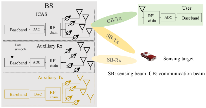
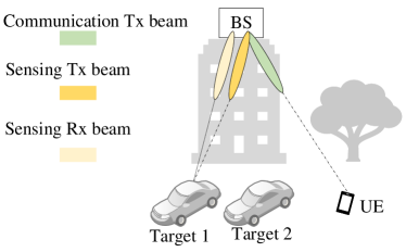
Let us consider a TDD base station based on fully connected analog array as in Fig. 1, where a JCAS aperture with antennas is supposed to communicate with a single-antenna user and illuminate the target via two beams. This aperture serves as the transmitter during downlink communication and as the receiver during uplink communication. Without loss of generality, we study the performance of only one RF chain of a fully connected analog array, since other RF chains are also connected to the same antennas. Due to long communication frames, full-duplex radar sensing functionality is mandatory for perpetual sensing of environment, therefore auxiliary apertures with antennas are needed to serve as radar receiver during downlink communication, and as radar transmitter during uplink communication111The reason for transmit antennas at the uplink is that sensing solely by the communication signal has the following problems, i.e., the power resources of communication users are limited so is the SNR for sensing, these users have also beamforming toward BS, therefore the environment is not illuminated for sensing, besides the sensing environment is dependent on the location of user which could be unknown, therefore transmit antennas at BS during uplink communication are beneficial for sensing [21].. The signal processing for downlink and uplink JCAS are different, i.e., reflected signals from sensing target and uplink communication signal from the user interfere at JCAS aperture which operates as the receiver, hence they need to be separated, whereas downlink sensing does not need such separation since the auxiliary Rx only receives the reflection from the target. In this paper, we choose downlink communication and sensing to demonstrate the performance of STPA. This performance is representative to the uplink communication and sensing, since the narrow beamwidth of the JCAS aperture as a receiver is beneficial for the sensing, and the spectral efficiency of uplink communication with the STPA is similar to the CUPA.
Radar has a two-way radiation pattern, and an ideal radar radiation pattern should be narrow in both transmit and receive pattern for optimal power usage, hence we study the challenging part where both communication and sensing are considered in a single JCAS aperture, the auxiliary arrays can be designed accordingly. One of the features of millimeter wave (mmWave) communication is the large number of antennas, which provides larger gain towards the user. Besides, the antennas in the JCAS aperture are used as transmitter for downlink sensing, therefore the transmit beam for sensing is already narrow and the auxiliary Rx can have less antenna numbers to decrease implementation costs, hence we assume . Therefore, the tiling is targeted only to the antennas at the JCAS aperture, and we simply choose and focus on the JCAS aperture for the performance study of STPA. We use communication signals with orthogonal frequency division multiplexing (OFDM) waveforms to communicate and sense.

II-B Realization of STPA
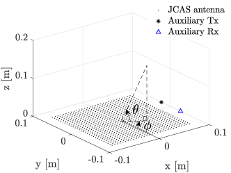
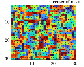
Note that the inherent problems of tiling of the JCAS aperture for the least SLL and a sparse aperture for the best AoA estimation are non-convex optimizations which are difficult to solve, therefore the optimization has to be based on the foreknowledge, hence local optimization is employed, as it is shown in the flowchart of Fig. 2. The main idea of this design is based on two scales of irregularity, namely the geometry of subarrays (local scale), and the phase centers of tiles in the whole aperture (global scale). Initially, a large CUPA is tiled for the minimum SLLs in the radiation pattern. The tiling problem is formulated based on maximum entropy in the distribution of the phase centers of the tiles in the array. In the JCAS aperture shown in Fig. 3, assume antennas are grouped in tiles and fed by power dividers. The center of mass of such a tile could be considered as the center of phase for the radiation from the whole tile. The irregularity in the distributions of these phase centers is measured with an information-theoretic entropy-based objective function, i.e., if the entropy of phase centers at each row and column of the aperture is maximized, then the resulting phased array aperture has a desired SLL while scanning. To obtain more mathematical insight into tiling based on the maximum entropy, refer to [24]. The resultant tiled array can still be thinned by grouping some tiles in subarrays and removing others. A subarray is determined by a circle circumventing its tiles, the centers of these circles (subarrays) are obtained by the geometry of the sunflower array since the positions of elements are controllable, although it is an aperiodic sparse array (see appendix A). The radius of a circle is a thinning parameter for the aperture, which can be tuned to reach the desired SLL with minimum number of tiles. It is assumed that the phase centers of tiles are still distributed with a maximum entropy after thinning of aperture, but the inter-distances among subarrays increase the SLL, however the resultant empty space among subarrays can be exploited to optimize the location of subarrays efficiently to decrease the SLL (see appendix B). Once the JCAS aperture with the minimum number of phase shifters, the desired SLL and beamwidth is achieved, its performance is compared to CUPA.
II-B1 Expanded Beam Pattern
In order to assure that the designed STPA bears the desired SLL and beamwidth in various scanning scenarios, the expanded beam pattern (EBP) is employed, which facilitates studying SLLs for all scanning angles in a single radiation pattern. The radiation field of an array with isotropic radiating elements in -space can be obtained by:
| (1) |
where is the number of radiating elements, and are the amplitude and phase of excitation, respectively. is the wave-number at the wavelength , and are the positions of antennas in Cartesian coordinates. is the elevation angle measured from -plane and is the azimuth angle measured from -axis. The radiation field in (1) can scan toward the angle by the proper weighting of amplitudes and phases. In case of conventional beamforming, which is based on only phase excitation in the elements, the weights are:
then the radiation pattern is:
| (2) |
In order to simplify studying the above radiation pattern for all s, the EBP is defined as [8]:
where , . The scanning of beam in the whole without grating lobes is not practical, therefore the desired angle of view is where is the minimum of angle . The SLL for is studied to ensure an appropriate SLL in all scanning angles.
II-C Performance Metrics
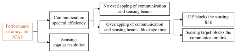
The performance metrics for communication and sensing are spectral efficiency and angular resolution, respectively, as it is shown in the flowchart of Fig. 4. The communication performance (CP) includes cases without and with overlapping of beams when the UE blocks the sensing link and also when the sensing target blocks the communication link. The overlapping occurs when:
| (3) |
where and are the angles of communication and sensing beams, respectively, and is the radius of the beamwidth in -space. In pursuit of simplicity, we suppose the user has no reflection of electromagnetic waves and all the energy transmitted in the communication beam of the BS is captured by the user.
II-C1 CP without overlapping communication and sensing beams
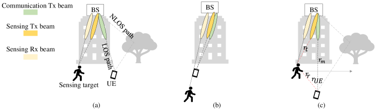
Let us consider the scenario in Fig. 5(a). A geometric model for both communication and sensing including multipath signals with the angle of departure and AoA is assumed, then the time varying channel would be:
| (4) |
where is the complex value modelling signal attenuation, is the propagation delay and is the Doppler frequency. and are the steering vectors for transmit and receive arrays. The channel (4) might also include the LOS path for communication. The multibeam weighting vector at the JCAS aperture is [18]:
| (5) |
where is the power allocation factor between beams which equals to 0.5 in this paper, is the weighting vector for communication and denotes the weighting vector for sensing to a desired direction . For simplicity, is considered as the right singular vector of the channel corresponding to the maximum singular value of with whereas . In this paper, the performance metric for communication is spectral efficiency, and when Gaussian symbols are transmitted in a mmWave channel, the spectral efficiency is [25]:
| (6) |
where denotes the variance of a zero-mean Gaussian noise.
II-C2 CP with overlapping beams when the UE blocks the sensing link
When the UE blocks the sensing link, the two beams are united and the whole energy is captured by the UE, then the spectral efficiency is increased. This happens either in the scanning mode of sensing or the tracking mode with the range of target being larger than the range of UE as in Fig. 5(b). The model for this case, due to its simplicity, is not considered here and will only be shown via simulation.
II-C3 CP with overlapping beams when the sensing target blocks the communication link
Let us study the overlapping when the range of the target is smaller than the range of a single-antenna UE, as in Fig. 5(c). It is supposed that the target occupies only one angle step, is tracked, and the sensing beam is aligned with the angle of the target. When this target moves toward the communication link, the beams are overlapping, the LOS link is vanished and blockage occurs. In order to model the blockage, the following channel model is considered with and without blockage [26, 27]:
| (7) |
where:
| (8) |
where is the same channel (4) as described in section C.1, and denote the channel of BS-target-UE before or after the blockage and during the blockage, respectively. and are the distance between the target and the BS, and the target and the UE, respectively. Let us suppose a human as the target, therefore which models the reflection and scattering is calculated by [26]:
| (9) |
where is the incident angle on the body, is the complex permittivity of the body and a zero-mean Gaussian random variable with a standard deviation of models the non-flat body and swinging limbs. Besides, when the human blocks the LOS link, the result is dB attenuation of power at the receiver UE [28], therefore which denotes the diffraction coefficient, simply equals to at the operation frequency of GHz. We assume the target moves in a line perpendicular to the LOS path where and only the angle varies, and its Doppler effects on are negligible. The channel modeled in is used for calculating the spectral efficiency.
II-D Sensing performance of JCAS aperture
The main sensing feature of the designed JCAS BS in Fig. 5(a) is the angular resolution due to its narrow beamwidth, which will be demonstrated by two angularly adjacent targets. The sensing here is based on the phased array where at each angle, the range and velocity are estimated. Similar to [18], the same OFDM waveform is used for JCAS and sensing should be performed during multiple sets of symbols; symbols are required for the coherent processing for Doppler estimation at each angle, where and are the number of elevation and azimuth angles, respectively, resulting in angles for full sensing of space. Here, we suppose that self-interference is already cancelled by a combination of passive [29] and active methods [21, 30], therefore the received signal at the auxiliary Rx is simplified by:
| (10) |
where is the received signal at th subcarrier when sensing the angle indexed by where , and . While is the symbol duration, . is the noise sample and is the baseband signal for subcarrier . It is assumed that the communication beam is constant during , the time of one communication packet. At each scanning angle, and consequently in (5) are calculated, then the inverse discrete Fourier transform (DFT) and DFT are applied to the received signal to extract the range and Doppler of targets, respectively.
III Numerical Analysis
III-A JCAS Array Aperture – A Design Example
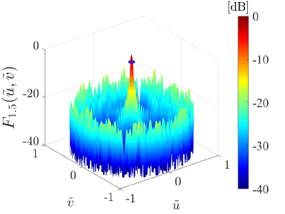
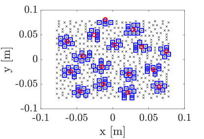
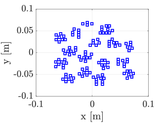
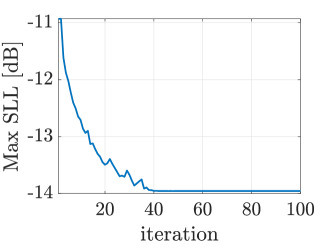
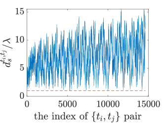
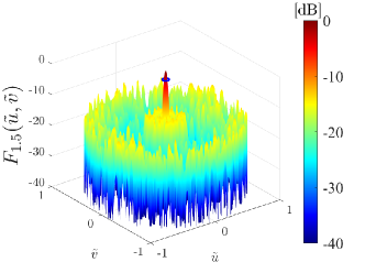
Let us consider a uniform array for the JCAS aperture with , with inter-element distance where is the wavelength at the center frequency of operation GHz. Firstly, these antennas are tiled with dominoes based on the maximum entropy, as in Fig. 6(a). In order to show the capability of this large tiled array when scanning to according to 5G base station requirements [12], its EBP which corresponds to the scanning by linear beamforming is shown in Fig. 6(b), where the maximum SLL is dB and the beamwidth is . Then, the sunflower array is used to thin these dominoes. In order to cover the whole aperture, the distance between elements of the sunflower array is , while the angle steps of these elements are golden ratio . The domino tiles which are in distance from the elements of sunflower are chosen for the subarrays and the thinning rate depends on this . The simulation showed that provides the best performance for low SLL and minimum required tiles, which results in overall 125 dominoes as shown in Fig. 7. This elimination of dominoes increases maximum SLL, and reaches dB, however the locations of subarrays can also be optimized for improving the SLL via iterative convex optimization (see appendix B). The parameters in the position optimization of subarrays for an EBP with are for the main beamwidth and for the maximum of position steps. The angles and are swept with . The objective function is to minimize the maximum SLL in the EBP. As is shown in Fig. 8(a)-(b), the optimization reaches a maximum SLL of dB. For mutual coupling and implementation considerations, the inter-distances of each tile in a subarray with the adjacent tiles in other subarrays are checked to be larger than which is shown in Fig. 8(c). The EBP of the final geometry, has an SLL of dB (due to the linear approximation in the optimization) while having a beamwidth of as it is shown in Fig. 8(d). This final array geometry in Fig. 8(a) will be employed as the JCAS aperture.
III-A1 Robustness of STPA to wideband operation
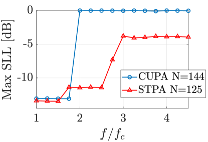
The array factor is the radiated field of the array when antennas are isotropic, and is critical for wideband operation. Fig. 9 demonstrates how this designed aperture performs with an increase in the frequency of operation. Where the EBP of STPA at still shows a maximum SLL of -11.44 dB, the CUPA with 144 antennas suffers from high SLL (grating lobes). Considering 1.75 and 2.5 as maximum frequencies for CUPA and STPA, respectively, STPA contributes to 42% improvement in maximum operational frequency of the array.
III-A2 Practical STPA design
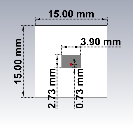
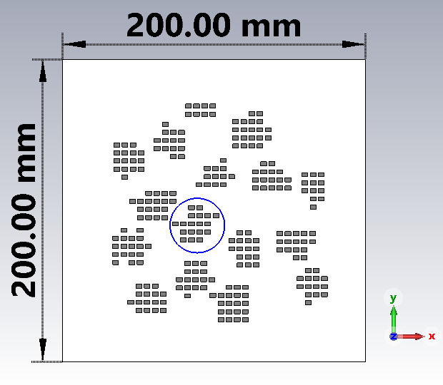
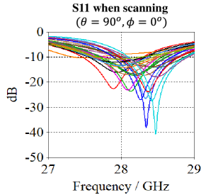
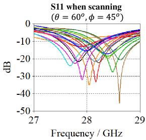
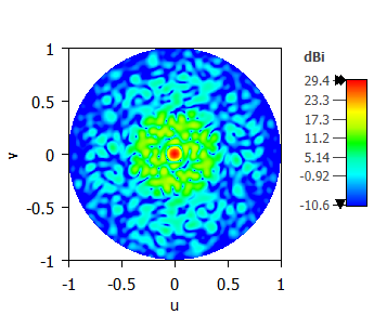
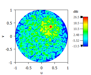
An example of an STPA is simulated in CST Studio. The radiating elements are patch antennas as in Fig. 10(a) and designed on the Rogers RO3003 substrate with thickness of mm, relative permittivity of , copper cladding thickness of 35 m and excited by a discrete port. At GHz, the 10dB-bandwidth is MHz and 3dB-beamwidth is for various s. Upon the knowledge of the positions of phase centers for tiles as shown in Fig. 8(a) and the orientation of dominoes (horizontal or vertical), the STPA has obtained and shown in Fig. 10(b). The radiation from the STPA can be simulated by simultaneous excitation of the two horizontally or vertically juxtaposed patch antennas (corresponding to a tile) with the same phase. The number of patch antennas is 250 whereas the number of phase shifters and tiles is 125. As an example, the S11 parameters of 18 antennas (9 dominoes) at subarray 1 are shown in Fig. 10(c) when all antennas are excited simultaneously for scanning and Fig. 10 (d) for scanning . The changes in the resonance frequency and magnitude of S11 are noticeable due to the mutual coupling effects. The radiation from the STPA at the frequency of GHz and beamformed to boresight is shown in Fig. 10(e) where the maximum directivity is dBi, the 3dB-beamwidth is and the maximum SLL is dB, whereas in case of beamformed towards , the maximum directivity is dBi, the maximum SLL reaches dB and beamwidth to as shown in Fig. 10(f). The decrease of directivity and SLL suppression in the full-wave simulations is due to the non-isotropic radiation of patch antennas, the mutual coupling effects and the asymmetric radiations of horizontal and vertical tiles.
III-B Performance metrics
Once the practicality of STPA is demonstrated by full-wave simulation, we will proceed with simple isotropic modelling of radiating elements for analyzing the performance for the communication and sensing in comparison with CUPA.
III-B1 CP without overlapping communication and sensing beams
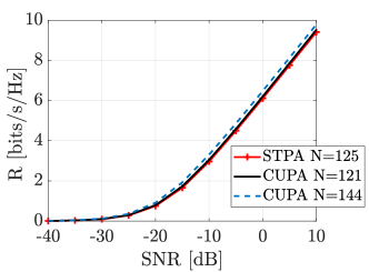
We consider the situation Fig. 5(a) and assume a user is at the range of m and the angle of . The channel in (4) from the JCAS aperture to the user is modeled by a dominant LOS path, besides NLOS paths which include clusters each with rays and having 10 dB power less than the LOS path. The overall power of the channel, including LOS and NLOS path, is normalized for the channel as in [12]. The scatters are distributed uniformly within all elevations and azimuth angles. The channel from BS to the user via the target is also considered in the NLOS path. Based on the estimated channel and desired scanning angles, and based on that, the spectral efficiency can be calculated. The average of from 200 channel realizations is obtained for the designed STPA. We intend to compare the performance of STPA with a symmetrical CUPA, so the closest numbers of antennas of CUPA are and . As it is shown in Fig. 11, all three antenna configurations (STPA and 2 times CUPA) have similar performances, where CUPA with and has slightly better spectral efficiency due to their higher directivity.
III-B2 CP with overlapping communication and sensing beams when the UE blocks the sensing link
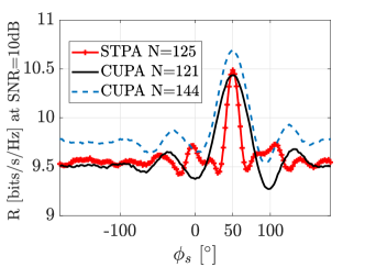
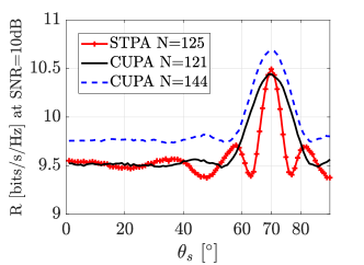
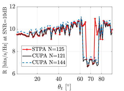
As the same waveform is used for both beams, when overlapping occurs either in the scanning mode, or in the tracking mode with the range of the tracking target being larger than the range of the UE, which is the case in Fig. 5(b), the signal power at the UE is increased, therefore spectral efficiency is supposed to increase. Let us consider the user is at the angle , the sensing is in the scanning mode and the sensing beam first scans over azimuth at the elevation and then over elevation at azimuth angles. The average spectral efficiencies at an SNR of 10 dB is presented in Fig. 12(a) and (b). The deviation from the spectral efficiency without overlapping is noticeable for the STPA only when the difference of communication angle and scanning angle is , whereas this number for the CUPA with and antennas is . The Fig. 12(a) and (b) and above discussion are also valid for the tracking mode of a target with larger range than the UE, e.g., m and m. Regarding sensing performance in these cases, the received signal at the BS from the scanning beam when it reaches the angle of the UE, is zero due to zero reflection. In the overlapping when the tracked target is behind the UE, the received reflected signal at the BS is again zero and the target is also lost. The spectral efficiency of the communication link increased since the sensing and communication beam have the same waveform, if one intends to use separate waveforms in separate beams then beam overlapping is detrimental for the SNR at the user.
III-B3 CP with overlapping communication and sensing beams when the sensing target blocks the communication link
The range for UE is considered to be m, the target body moves at the constant azimuth of , perpendicular to the LOS path and crossing it at m as in Fig. 5(c). The parameters for the body in (9) are assumed as , dB [26] and the incident angle on the body . The variation of spectral efficiency at an SNR of 10 dB for the STPA and CUPAs are shown in Fig. 13. There is an increased oscillation in the spectral efficiency just before and after blockage occurrence, which is due to constructive addition of and [31]. The most noticeable difference between the STPA and CUPAs is the time of blockage where the STPA, due to its narrower beamwidth, has shorter time. In these scenarios, the blockage time is proportional to the overlapping angles of communication and sensing beam, hence it is observed in Fig. 13 that the STPA has a 40 shorter blockage time than CUPAs in the elevation sensing.
| Parameter | Value | Description |
|---|---|---|
| 28 GHz | Carrier frequency | |
| 40 MHz | Bandwidth | |
| 2048 | Number of subcarriers | |
| 51.2 s | Symbol duration | |
| 3.75 m | Range resolution | |
| 3.07 m/s | Velocity resolution | |
| 52.32 m/s | Maximum unambiguous velocity | |
| 7680 m | Maximum unambiguous range |
III-B4 Sensing performance of JCAS aperture
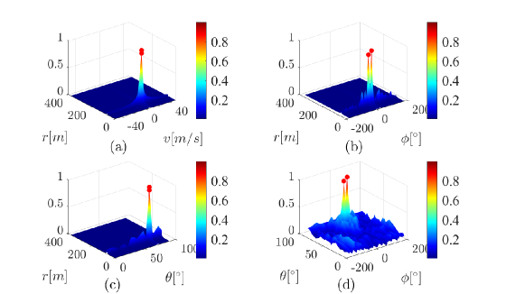
One of the key performance metric for sensing is the angular resolution in the scanning mode, which is studied for the STPA in comparison to CUPA with antennas. Let us consider an outdoor scenario as in Fig. 14 where, in the worst case, two targets are located at the same ranges of m, velocities of ms and the elevation of but in different azimuth angles. The OFDM simulation parameters are shown in the Table I. The radiation gain of JCAS tiles and auxiliary antennas, the radar cross-section of targets and the noise figure of the receiver are assumed to be unit, then the two-way channel gain in (4) is simply .
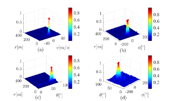
The coherent processing duration for Doppler estimation is where . A communication packet includes symbols, where is the number of elevation angles and scanning in azimuth is performed during communication packets, hence the elevation and azimuth angles are swept by . The variance of noise in (10) is considered to be 10 dB lower than the received target signal. As the emphasis here is on the angular resolution of JCAS aperture, we assume the angle differences of targets are only in azimuth and compare the angle estimation of targets between the STPA and the CUPA with . The range, velocity and elevation angle of targets are shown in Fig. 15(a) and (c) for the CUPA, and in Fig. 16(a) and (c) for the STPA. Both arrays provide a true estimation of these features of targets. However, comparing the results in Fig. 15(b) and (d) and Fig. 16(b) and (d) show that the designed STPA is capable of distinguishing two adjacent targets in and where the CUPA with more number of antennas cannot. Therefore, the STPA provides a high angular resolution image during the scanning mode of sensing.
III-C Discussion
In this paper, we assumed a scenario with a dominant LOS path, therefore the increase in the average SLL due to tiling and sparse design is not detrimental. The effect of interference on the JCAS performance of the STPA for NLOS case is still an open question. As future work, the aperture efficiency of the designed STPA should also be improved. This can be tackled by assigning tiles with different sizes to outer subarrays. Besides, this study can be extended to hybrid beamforming arrays combined with phased-MIMO radar concepts.
IV Conclusion
Analog beamforming arrays can increase the gain of radiation and overcome propagation attenuation in millimeter wave communication and sensing links, therefore in alliance with the fully-connected analog beamforming arrays, a tiled sparse planar array (STPA) is proposed with modular design, narrow beamwidth and decreased number of phase shifters for joint communication and sensing applications. The design is based on maximum entropy in the phase centers of the tiles in the array and sparse subarrays. The results show that an STPA with 125 domino tiles has stable radiation up to 2.5 times the center frequency of operation, , whereas the maximum frequency of operation is for CUPA with 144 antennas. A realistic radiation pattern of STPA, including antenna imperfections, is shown by full-wave simulation. When the sensing and communication beams are not overlapping, CUPA and STPA guarantee the same spectral efficiency in the communication link, whereas a better angular resolution in sensing is achieved by the STPA, e.g., two targets in the proximity of boresight are distinguished while their azimuth is 20∘ different. The analysis also includes the overlapping of communication and sensing beams and a blockage scenario by a tracked target. As the STPA has a narrower beamwidth than the CUPA, the blockage time is 40 shorter while the tracked target moves in the elevation angles.
V Acknowledgment
This work has received funding from the Dutch Sector Plan and the MSCA-IF-2020 V.I.P. project No. 101026885.
VI Appendix
VI-A Sunflower array
The sunflower array can demonstrate the same radiation pattern as a uniform array, but with a lower number of antennas. In polar coordinates, the th element of the sunflower array is obtained by [13]:
| (11) |
where is the inter-distance of elements, denotes the golden ratio and is the number of elements.
VI-B Position optimization
The positions of subarrays are optimized based on an iterative convex optimization. Let us consider the expanded radiation field of the array in -space as:
| (12) |
As it is discussed in [32], when the positions of antennas are optimization variables, the problem is nonlinear and non-convex, however it can be solved as a convex problem iteratively by first-order Taylor expansion as in:
| (13) |
where denotes the iteration index, and and are the movement in and axes at th iteration, respectively. and are the position in and axes at th iteration, respectively. (13) is a linear convex function that can be solved by Matlab CVX [33]. To enforce only subarray movements, s are equal for all antennas in a subarray. Finally, the optimization can be written as:
| (14) | ||||
| s.t. | ||||
where and . is the set of all side lobe angles and is a predetermined number. As the elements are domino tiles, there should be a distance of at least between the phase center of each domino at one subarray with the phase centers of other dominoes at adjacent subarrays for fabrication possibility. This could also be added as a constraint to (14) as discussed in [32].
References
- [1] C. De Lima, D. Belot, R. Berkvens, A. Bourdoux, D. Dardari, M. Guillaud, M. Isomursu, E.-S. Lohan, Y. Miao, A. N. Barreto et al., “Convergent communication, sensing and localization in 6g systems: An overview of technologies, opportunities and challenges,” IEEE Access, vol. 9, pp. 26 902–26 925, 2021.
- [2] H. Alidoustaghdam, Y. Miao, and A. Kokkeler, “Integrating tdd communication and radar sensing in co-located planar array: A genetic algorithm enabled aperture design,” in 2022 2nd IEEE International Symposium on Joint Communications & Sensing (JC&S), 2022, pp. 1–6.
- [3] J. A. Zhang, F. Liu, C. Masouros, R. W. Heath, Z. Feng, L. Zheng, and A. Petropulu, “An overview of signal processing techniques for joint communication and radar sensing,” IEEE Journal of Selected Topics in Signal Processing, 2021.
- [4] G. Oliveri, G. Gottardi, and A. Massa, “A new meta-paradigm for the synthesis of antenna arrays for future wireless communications,” IEEE Transactions on Antennas and Propagation, vol. 67, no. 6, pp. 3774–3788, 2019.
- [5] Y. Ma, F. Yang, K. Chen, S. Yang, Y. Chen, S.-w. Qu, and J. Hu, “An irregular tiled array technique for massive mimo systems,” IEEE Transactions on Wireless Communications, 2021.
- [6] F. Athley, C. Engdahl, and P. Sunnergren, “On radar detection and direction finding using sparse arrays,” IEEE Transactions on Aerospace and Electronic Systems, vol. 43, no. 4, pp. 1319–1333, 2007.
- [7] X. Meng, F. Liu, C. Masouros, W. Yuan, Q. Zhang, and Z. Feng, “Vehicular connectivity on complex trajectories: Roadway-geometry aware isac beam-tracking,” arXiv preprint arXiv:2205.11749, 2022.
- [8] A. Gupta, U. Madhow, A. Arbabian, and A. Sadri, “Design of large effective apertures for millimeter wave systems using a sparse array of subarrays,” IEEE Transactions on Signal Processing, vol. 67, no. 24, pp. 6483–6497, 2019.
- [9] Y. Ma, S. Yang, Y. Chen, S.-W. Qu, and J. Hu, “Pattern synthesis of 4-d irregular antenna arrays based on maximum-entropy model,” IEEE transactions on antennas and propagation, vol. 67, no. 5, pp. 3048–3057, 2019.
- [10] N. Anselmi, P. Rocca, M. Salucci, and A. Massa, “Irregular phased array tiling by means of analytic schemata-driven optimization,” IEEE Transactions on Antennas and Propagation, vol. 65, no. 9, pp. 4495–4510, 2017.
- [11] W. Dong, Z.-H. Xu, X.-X. Li, and S.-P. Xiao, “Low-cost subarrayed sensor array design strategy for iot and future 6g applications,” IEEE Internet of Things Journal, vol. 7, no. 6, pp. 4816–4826, 2020.
- [12] Y. Ma, F. Yang, M. Huang, C. Sun, Y. Chen, S.-W. Qu, and S. Yang, “A thinned irregular array synthesis approach based on benders decomposition,” IEEE Transactions on Antennas and Propagation, vol. 69, no. 7, pp. 3875–3885, 2020.
- [13] M. C. Viganó, “Sunflower array antenna for multi-beam satellite applications,” 2011.
- [14] Y. Aslan, J. Puskely, A. Roederer, and A. Yarovoy, “Synthesis of quasi-modular circularly polarized 5g base station antenna arrays based on irregular clustering and sequential rotation,” Microwave and Optical Technology Letters, vol. 63, no. 4, pp. 1278–1285, 2021.
- [15] Y. Aslan, A. Roederer, and A. Yarovoy, “System advantages of using large-scale aperiodic array topologies in future mm-wave 5g/6g base stations: An interdisciplinary look,” IEEE Systems Journal, 2021.
- [16] M. Vigano, G. Toso, G. Caille, C. Mangenot, and I. Lager, “Spatial density tapered sunflower antenna array,” in 2009 3rd European Conference on Antennas and Propagation. IEEE, 2009, pp. 778–782.
- [17] M. Temiz, E. Alsusa, and M. W. Baidas, “A dual-functional massive mimo ofdm communication and radar transmitter architecture,” IEEE Transactions on Vehicular Technology, vol. 69, no. 12, pp. 14 974–14 988, 2020.
- [18] J. A. Zhang, X. Huang, Y. J. Guo, J. Yuan, and R. W. Heath, “Multibeam for joint communication and radar sensing using steerable analog antenna arrays,” IEEE Transactions on Vehicular Technology, vol. 68, no. 1, pp. 671–685, 2018.
- [19] M. Temiz, E. Alsusa, and M. W. Baidas, “A dual-functional massive mimo ofdm communication and radar transmitter architecture,” IEEE Transactions on Vehicular Technology, vol. 69, no. 12, pp. 14 974–14 988, 2020.
- [20] Z. Ni, J. A. Zhang, X. Huang, K. Yang, and J. Yuan, “Uplink sensing in perceptive mobile networks with asynchronous transceivers,” IEEE Transactions on Signal Processing, vol. 69, pp. 1287–1300, 2021.
- [21] M. Temiz, E. Alsusa, and M. W. Baidas, “A dual-function massive mimo uplink ofdm communication and radar architecture,” IEEE Transactions on Cognitive Communications and Networking, 2021.
- [22] Y. Ma, S. Yang, Y. Chen, S.-W. Qu, and J. Hu, “Pattern synthesis of 4-d irregular antenna arrays based on maximum-entropy model,” IEEE Transactions on Antennas and Propagation, vol. 67, no. 5, pp. 3048–3057, 2019.
- [23] T. G. Spence and D. H. Werner, “Design of broadband planar arrays based on the optimization of aperiodic tilings,” IEEE Transactions on Antennas and Propagation, vol. 56, no. 1, pp. 76–86, 2008.
- [24] Y. Ma, S. Yang, Y. Chen, S.-W. Qu, and J. Hu, “High-directivity optimization technique for irregular arrays combined with maximum entropy model,” IEEE Transactions on Antennas and Propagation, vol. 69, no. 7, pp. 3913–3923, 2020.
- [25] O. El Ayach, S. Rajagopal, S. Abu-Surra, Z. Pi, and R. W. Heath, “Spatially sparse precoding in millimeter wave mimo systems,” IEEE transactions on wireless communications, vol. 13, no. 3, pp. 1499–1513, 2014.
- [26] A. Bhardwaj, D. Caudill, C. Gentile, J. Chuang, J. Senic, and D. G. Michelson, “Geometrical-empirical channel propagation model for human presence at 60 ghz,” IEEE Access, vol. 9, pp. 38 467–38 478, 2021.
- [27] R. Hersyandika, Y. Miao, and S. Pollin, “Guard beam: Protecting mmwave communication through in-band early blockage prediction,” 2022. [Online]. Available: https://arxiv.org/abs/2208.06870
- [28] U. T. Virk and K. Haneda, “Modeling human blockage at 5g millimeter-wave frequencies,” IEEE Transactions on Antennas and Propagation, vol. 68, no. 3, pp. 2256–2266, 2019.
- [29] B. Nuss, L. Sit, M. Fennel, J. Mayer, T. Mahler, and T. Zwick, “Mimo ofdm radar system for drone detection,” in 2017 18th International Radar Symposium (IRS). IEEE, 2017, pp. 1–9.
- [30] C. B. Barneto, T. Riihonen, M. Turunen, L. Anttila, M. Fleischer, K. Stadius, J. Ryynänen, and M. Valkama, “Full-duplex ofdm radar with lte and 5g nr waveforms: Challenges, solutions, and measurements,” IEEE Transactions on Microwave Theory and Techniques, vol. 67, no. 10, pp. 4042–4054, 2019.
- [31] S. Wu, M. Alrabeiah, C. Chakrabarti, and A. Alkhateeb, “Blockage prediction using wireless signatures: Deep learning enables real-world demonstration,” IEEE Open Journal of the Communications Society, vol. 3, pp. 776–796, 2022.
- [32] Y. Aslan, J. Puskely, A. Roederer, and A. Yarovoy, “Multiple beam synthesis of passively cooled 5g planar arrays using convex optimization,” IEEE Transactions on Antennas and Propagation, vol. 68, no. 5, pp. 3557–3566, 2019.
- [33] M. Grant, S. Boyd, and Y. Ye, “Cvx: Matlab software for disciplined convex programming, version 2.0 beta,” 2013.