email: ]pengning@princeton.edu ††thanks: These two authors contributed equally
Maximum Electromagnetic Local Density of States via Material Structuring
Abstract
The electromagnetic local density of states (LDOS) is crucial to many aspects of photonics engineering, from enhancing emission of photon sources to radiative heat transfer and photovoltaics. We present a framework for evaluating upper bounds on the LDOS in structured media that can handle arbitrary bandwidths and accounts for critical wave scattering effects. The bounds are solely determined by the bandwidth, material susceptibility, and device footprint, with no assumptions on geometry. We derive an analytical expression for the maximum LDOS consistent with the conservation of energy across the entire design domain, which upon benchmarking with topology-optimized structures is shown to be nearly tight for large devices. Novel scaling laws for maximum LDOS enhancement are found: the bounds saturate to a finite value with increasing susceptibility and scale as the quartic root of the bandwidth for semi-infinite structures made of lossy materials, with direct implications on material selection and design applications.
I Introduction
The electromagnetic local density of states (LDOS), a measure of local response—the electric field from a dipolar current source—at a given point in space [1], plays a central role in many nanophotonic phenomena and applications, including spontaneous [2] and stimulated [3] emission, quantum information [4], surface enhanced Raman scattering [5, 6], photovoltaics [7], radiative heat transfer [8], non-linear frequency conversion [9], scintillation [10], to name a few. Enhancing the LDOS by nanostructuring bulk media, a persistent theme in photonics design, is often achieved through the creation of optical resonances [11]: a cavity or resonator supporting a single mode of quality factor and mode volume enhances the LDOS in proportion to the Purcell factor . Many classic design schemes rely on maximizing (ring resonators [12]), minimizing (plasmonic nanocavities [13, 14], bow-tie antennae [15]), or a combination thereof (photonic crystal cavities [16], metal-dielectric hybrid structures [17]). Going beyond the single mode picture, multi-mode and dispersion-based effects such as exceptional points [18, 19] and slow light devices [20] have also been explored. Recently, complex devices obtained by application of large-scale structural optimization appear to combine several confinement mechanisms [21, 22], providing further improvements on device performance.
Given its relevance in optics and the ever increasing structural freedom brought on by advances in nanofabrication [23], interest in assesing limits on achievable LDOS enhancement has grown over the past few decades [24]. Spectral sum rules [25, 26, 27] pin the frequency-integrated LDOS of any system but are of limited utility in practical settings involving finite and often narrow source bandwidths. Specialized results pertaining to achievable mode quality factors [28] or mode volumes in cavity settings [29] have proven useful in many applications but are not sufficiently general to account for multi-mode effects. Passivity requirements based on achievable material response were recently used to bound both single-frequency [30] and finite-bandwidth [31] LDOS. However, passivity alone cannot fully capture the wave nature of light as constrained by Maxwell’s equations, e.g., the necessity of phase matching to achieve resonance, leading to loose limits when contributions other than those coming from evanescent fields become relevant.
In this article, we generalize and lift several limitations imposed by these prior approaches to provide expressions and predictions for the largest spectral-integrated LDOS that may be achieved in a structured medium. The derived bounds incorporate wave and material constraints imposed by Maxwell’s equations over any desired length-scale and are geometry agnostic: besides specifying the material susceptibility , a frequency window of interest, and a bounding domain that the structured medium must reside within, no further assumptions are made on device topology. We consider sources both enclosed within and external to devices, obtaining bounds that generally come within an order of magnitude of complicated structures discovered through inverse methods [32]. Furthermore, we find that the mere requirement of energy conservation is sufficient to place tight limits on large devices; we exploit this fact to derive an analytical upper bound (13) along with integral expressions and asymptotic analysis for the particular scenario of a source above a semi-infinite, structured slab. The bounds show saturation to a finite value as and varying power-law scalings with respect to source bandwidth , with the maximum LDOS transitioning from a scaling to one as material absorption begins to limit the net enhancement that any one mode may contribute.
II Problem Formulation
Working in dimensionless units of , and considering only nonmagnetic materials, the partial LDOS at frequency and position along the direction can be shown to be, by Poynting’s theorem [33], directly proportional to the average power emitted by a harmonic dipole source at the same location,
| (1) |
where the electric field generated by the solves Maxwell’s equations,
| (2) |
Since real sources emit light over a finite bandwidth (e.g., the Planck spectrum of heated bodies or fluorescence/spontaneous emission linewidth of atoms [34]), we instead consider the more natural choice of a frequency average of over a Lorentzian lineshape centered at with bandwidth (corresponding source “quality factor” ):
| (3a) | ||||
As pointed out in [32], such a modified figure of merit not only captures the spectral lineshape of many practical sources [34], but also offers a computational and conceptual advantage: instead of evaluating the frequency integral in (3a) directly, one can instead carry out a complex- contour integral over the upper half plane and exploit causality to convert, using the residue theorem, the spectral average to the single complex-frequency and an electrostatic (zero-frequency) contribution:
| (4) |
Here , where is a unit amplitude electrostatic dipole and the field it generates; this electrostatic contribution leads to an all-frequency integrated sum rule in the wide bandwidth limit [27, 31]. In this paper we will be focusing on the practically important case of moderate or narrow source bandwidth with and thus will neglect the electrostatic term in (4) going forward.
Thus, the structural design problem for maximizing bandwidth-averaged LDOS can be formulated as
| (5a) | |||
| given the constraints | |||
| (5b) | |||
| (5c) | |||
where is a pre-specified design region that the structure resides within and the Fourier transform of the bulk material susceptibility evaluated at complex frequency . In later expressions we may suppress the dependence of time-harmonic variables for notation simplicity.
Due to the high dimensionality of the structural degrees of freedom and the non-convex dependence of the field on , it is generally not possible to solve for the global optimum of (5c) [35]. However, it is possible to exploit an alternative parametrization of the problem in which the polarization density rather than serve as optimizations degrees of freedom, to obtain bounds on applicable to any possible structure, given only the choices of design region and material susceptibility [24]. In this context, it becomes convenient to decompose the total field into the vacuum field emitted by the source and scattered field emitted by the polarization currents:
| (6) |
with denoting the vacuum dyadic Green’s function, the solution to
| (7) |
Note that our definition of the Green’s function has an extra global factor of compared to the standard definition. Similarly, the net power extracted from the dipole source can be decomposed into constant (structure-independent) vacuum and scattered-field contributions:
| (8a) | ||||
| (8b) | ||||
| (8c) | ||||
where in the second line of (8c) we made use of the fact that (the global phase of dipole source is irrelevant) and the reciprocity relation . They key to formulating a shape-independent bound on is to forgo the need for structural information by relaxing the requirement that satisfy Maxwell’s equations everywhere, imposing instead a smaller subset of wave constraints [24]. Such constraints can be indeed be derived from Maxwell’s equations through a complex frequency generalization of the time-harmonic Poynting’s theorem (see [24] and SI), giving
| (9) |
where is any spatial region within the design domain and we have defined the composite operator . Notably, (9) can be interpreted as a statement of the conservation of energy over each spatial region, requiring only specification of the allotted design footprint and available susceptibility . Note also that geometric information is contained only implicitly in , with material properties specified by the known complex scalar . The resulting optimization problem for the LDOS can be written as
| (10a) | |||
| such that | |||
| (10b) | |||
where is the projection operator into the region . Above, we employed Dirac bra-ket notation for brevity, with denoting the vector field over the design domain , is the conjugated inner product, and operator action . (10b) is a quadratically constrained linear program for . While direct optimization is still not guaranteed to find a global optimum due to the non-convexity of certain constraints in (10b), a bound on the problem can be computed efficiently via the Lagrange dual function [36, 24, 37], hereby referred to as the dual bound.
In principle, the maximum LDOS achievable in a structured medium is known to grow indefinitively in the single-frequency limit of . For instance, in lossless media, the whispering gallery modes of ring resonators and defect modes of photonic crystals exhibit exponential scaling in with increasing system size [38, 16], while their mode volumes either increase polynomially or remain constant, respectively, leading to exponential growth in the Purcell factor. Geometries with sharp tips can also give rise to field singularities and hence vanishing mode volumes [39]. However, in practice, finite source bandwidths, device footprint, and material losses limit the utility of diverging lifetimes, while fabrication imperfections and atomic-scale effects preclude realization of arbitrarily small features. As will be seen below, the imposition of finite and a minimum vacuum gap between source and medium regularizes such divergences, paving the way for investigations of LDOS growth characteristics in realistic settings. We also note that for finite the vacuum LDOS contribution diverges due to contributions from high frequencies. This is an artifact of the Lorentzian lineshape chosen and has little bearing on practical applications; the results presented will thus focus on the structural contribution which does remain finite.
To make explicit the scale invariance of Maxwell’s equations, all lengths are given in units of the center wavelength and normalized by the single-frequency vacuum dipole radiation .
III Numerical Results
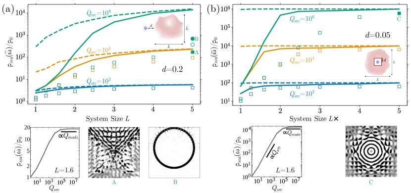
The dual bound can be obtained numerically for arbitrary domains via a suitable representation of the Green’s function and Maxwell operator. We do so for two standard settings: an external–dipole configuration where the dipole is adjacent to the structure, relevant for instance to gratings and solid-state defect couplers [40, 41]; and an enclosed–dipole configuration in which the dipole is surrounded by the structure, relevant to photonic crystal cavities [16], bullseye gratings [42], and bowtie antennas [15]. For computational convenience, all calculations are performed in 2d for both the out-of-plane (scalar) TM and in-plane (vectorial) TE electric-field polarizations. The finite-difference frequency-domain method is used to represent all relevant fields and operators (SI). Progressively tighter bounds were obtained by gradually increasing the number of constraint sub-regions down to the computational pixel level. Inverse designs were also obtained to compare against the bounds, following the topology optimization (TO) approach detailed in [32].
Results pertaining to maximum LDOS for both external and enclosed configurations are shown in Figure 1 as a function of the design footprint. Since the vacuum LDOS diverges when integrated against a Lorentzian lineshape [25, 32, 31], this and subsequent results pertain only to the structural contribution , defining the enhancement factor in relation to the single-frequency vacuum emission . In both settings the medium is assumed to be lossless, . For a fixed , the bounds are seen to grow exponentially before saturating with increasing domain size . Conversely, for fixed the bounds grow linearly before saturating with increasing . Both observations are consistent with a resonant enhancement mechanism: since the finite vacuum gap precludes field divergences in the vicinity of the dipole, thereby imposing an upper bound on its coupling to any mode, one would expect improvements in the Purcell factor to be mainly driven by growth in the modal lifetimes. Supposing a system with response dominated by a single mode of quality factor , (3a) yields a frequency-integrated LDOS that scales as
| (11) |
Thus, this modal picture predicts linear growth in (3a) so long as the system supports a sufficiently long-lived mode, , eventually saturating to a value whenever . In the absence of material dissipation, the highest achievable is constrained solely by radiative losses and, as confirmed by our bound calculations, known to scale at least exponentially with in ring-resonator and photonic-crystal cavities. Comparing our bounds (solid lines) against inverse designs (squares), one observes remarkable alignment, with bounds and designs often coming within an order of magnitude of each other. The biggest performance gaps occur at high in the external configuration and can at least be partially attributed to TO getting trapped in local optima that, regardless of exhaustive initial conditions, underperform simple ring resonator geometries. Even starting with ring resonators as initial seeds, TO was only able to make modest improvements. In contrast, Bragg–onion type structures discovered by TO in the cavity setting are seen to tightly approach corresponding bounds. Comparing the high degree of precision needed to specify the dimensions of the ring resonator against the relative robustness of photonic bandgap confinement [43], we hypothesize that attaining high-performing designs for the external configuration at narrow bandwidths requires resonances based on sensitive interference cancellation. This leads to an ill-behaved optimization landscape with many subpar local optima to get stuck in, with ring resonators as an example of a class of high-performing designs not easily discoverable via brute-force optimization.
Finally, the observed dependence of the dual bound on the number and size of subregion constraints (10b) reveals two important features: first, the necessity of imposing many subwavelength constraint regions (SI) for the bounds to exhibit saturation as ; second, the fact that a single, global energy-conservation constraint appears sufficient to produce tight bounds when either device sizes or source bandwidths become sufficiently large. This suggests that subregion constraints are necessary to adequately “resolve” wave effects, including phase-matching restrictions, that limit mode confinement in finite systems; conversely, when system sizes no longer limit the highest achievable in relation to , the latter and not the former becomes a bottleneck for further enhancements.
IV Large-size Semi-analytics
We now exploit the remarkable success of global energy conservation in describing large system behavior to obtain a semi-analytical bound on the maximum LDOS above a semi-infinite structure, i.e., the limit of the external–dipole configuration depicted in Figure 1a. As shown in SI, the solution of the dual problem under both resistive and reactive energy conservation constraints (10b) can be mapped to a family of solutions involving a unitary phasor parametrized by the single constraint angle , leading to the modified problem:
| (12a) | |||
| such that for , | |||
| (12b) | |||
where is the Hermitian anti-symmetric component of the operator . Owing to its simplicity, the solution to this dual bound for any given can be written explicitly as
| (13) |
which notably, depends only on the analytically known quantities , , and . The tightest dual bound consistent with (13) can thus be obtained numerically by carrying out an additional optimization over , restricted so that is positive definite (SI). Further analytical insight can be gleaned by expanding the operators and fields in a spectral basis conforming to the symmetry of the design domain: for a half-space enclosure, the natural choice is a Fourier basis parametrized by the wavevector parallel to the half-space surface. Carrying out this expansion for the incident field yields,
| (14a) |
where and . For each conserved , the inverse operator image can be similarly expanded and evaluated explicitly as the sum of two complex sinusoids, leading to
| (15) |
where the closed-form complex coefficients and decay constants are given in the SI.
The main challenge in evaluating (13) comes from the need to compute the inverse image of , which contains constraints on wave propagation via its dependence on the vacuum Green’s function . In that regard, it is useful to consider an expansion of (13) in orders of (after using the Cauchy-Schwartz inequality to relax the term involving (SI)):
| (16) |
The zeroth-order approximation given in (16) is especially simple to evaluate as it only depends on , and will hereafter be referred to as a material bound. A special yet sub-optimal value of in (16) recovers prior LDOS bounds based on passivity (SI) [31]. Notably, this zeroth order approximation becomes loose whenever is large as compared to ; this is the case for large or large design domains (e.g., the half-space) where dominates. Intuitively, terms containing the vacuum Green’s function capture physical limitations imposed by multiple scattering, screening, and the finite speed of light, which limit achievable LDOS.
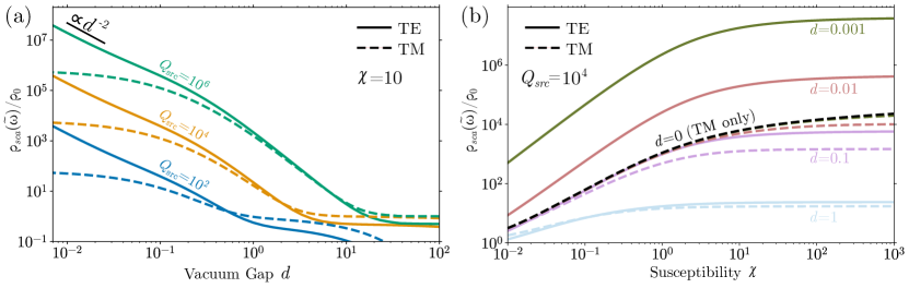
Figure 2 shows upper bounds on the LDOS for both TM and TE sources, obtained by evaluating (15). In the near-field limit of , the TM bounds are found to asymptote to a constant while the TE bounds scale , in agreement with a detailed asymptotic analysis of the evanescent behavior of the integrand in (15) (SI), and matching prior results based on passivity [31]. The constant asymptote observed for TM sources as they approach the device reflects a known artifact of 2d scalar electromagnetism, which precludes non-integrable field singularities at sharp corners [44]. In contrast, the scaling of TE sources confirms the known divergence in the energy concentration of a vector dipole in its near field, with the exponent of tied to the number of spatial dimensions; note that the maximum LDOS for a 3d source grows as (SI).
In the opposite far-field limit of and for finite , the bounds ultimately tend toward zero, reflecting a kind of space–bandwidth constraint on the ability of structuring to affect far-field emission over a finite bandwidth. One can, however, observe plateaus ocurring at intermediate regimes, , wherein structuring can efficiently reflect traveling planewaves back onto the dipole position. Achievable enhancements in this regime can be shown to decay , manifesting as plateaus in the various plots of Figure 2b. Only in the strictly single-frequency limit do far-field LDOS contributions tend toward constants, and for TE and TM sources, respectively, independently of separation. The importance of properly capturing relevant wave interference effects in these far-field regimes becomes evident when analyzing corresponding predictions for material bounds [31], which exhibit drastically inflated scaling in this half-space setting (SI).
Asymptotic analysis of (15) supported by Figure 2b reveal that LDOS enhancements saturate to finite values as (SI), in contrast to prior bounds which grow indefinitely with increasing material response [31]. This is somewhat surprising given that larger implies a larger (potentially infinite) density of states within the material itself; ultimately, multiple scattering and screening effects lead to restrictions on the possible field localization at the source location that cannot be overcome with clever structuring. Similar conclusions have been reached concerning the efficacy of hyperbolic metamaterials [45] at enhancing the LDOS in that particular geometry class. It is also worth noting that the saturation characteristics of the full bounds as a function of is distinct for the TM and TE polarizations. For TM, reducing increases the relative advantage of stronger materials; as whereas is finite as (SI). In contrast, for TE the saturation behavior for large scales uniformly with ; decreasing separation does not increase the relative advantage of stronger materials.
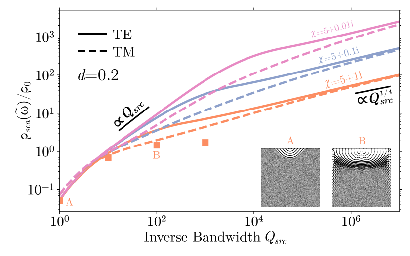
With regard to bandwidth scaling, the broad structural freedom afforded by an infinite design domain coupled with the lack of material dissipation allows for creation of resonances with arbitrarily small radiative loss rates, , leading to the same dependence observed in Figure 1. The situation changes in dissipative media where mode lifetimes contain both radiative and absorptive contributions, with denoting the proportion of stored energy dissipated in the medium per unit cycle. Hence, under finite absorption, sets a bound on the highest achievable mode lifetime, with (11) suggesting a saturating LDOS as .
In contrast, Figure 3 shows that the bounds exhibit a transition from the linear scaling of a wide-bandwidth source coupled to a single resonance toward diverging response as , with the transition taking place as . Intuitively, in this regime wherein the lifetime of a single resonance is capped, one might expect the optimal design strategy to shift toward exploiting degeneracies. One class of geometry capable of achieving high modal degeneracies are waveguides, e.g., coupled cavities or photonic crystal gratings, which at least in 1d are known to generate van Hove singularities in the density of states [46]. Generally, a spectral singularity of the form will yield a Lorentzian-averaged LDOS that scales as
| (17) |
The bounds for the 2d half-space configuration thus suggest the possibility of near-field absorbers supporting quartic “band-edge” dispersions capable of efficiently extracting evanescent fields, resulting in singularities of the form (anomalous quartic ”slow” group-velocity dispersions have been studied, for instance, in the context of waveguide solitons[47]). Indeed, TO discovers structures resembling adiabatic gratings (Figure 3 insets) and exhibiting the predicted quartic bandwidth scaling, though eventually saturating due to the finite computational domain (SI).
V Summary
We proposed an improved framework for evaluating upper bounds on the LDOS in structured media, and study in detail the effects of source bandwidth, material susceptibility, and device footprint. The bounds provide a strong top-down complement to bottom-up design in at least two ways: First, they are useful in quantifying the optimality of existing ”best” structures while diagnosing potential areas of improvement: as seen in narrow bandwidth regimes, existing formulations of inverse design fail to converge upon structures with performance close to the global optimum, often outperformed by traditional ring resonators. Second, they allow studies of fundamental scaling characteristics without prior assumptions on device topology.
For finite bandwidths, the quick saturation of the bounds with design size indicate that a device footprint of a few wavelengths is generally enough to achieve near-optimal performance. The observed saturation with increasing susceptibility has direct implications for material choice: a weak material response can be mitigated given sufficient design size and judicious structuring; conversely there are diminishing returns associated with seeking large absolute values of the susceptibility, raising the importance of other concerns such as material loss and dispersion characteristics. The impact of material loss was also evaluated in the context of maximum LDOS above a semi-infinite structure, showing a transition from the intuitive linear scaling expected of single-mode resonant enhancement to a less obvious dependence given absorptive materials, inviting further studies into the associated dispersion engineering mechanisms making such scaling possible. While only results for dielectrics () where shown in this paper, the framework can handle metals () just as well, yielding broadly similar conclusions.
VI Acknowledgments
This work was supported by the National Science Foundation under the Emerging Frontiers in Research and Innovation (EFRI) program, Award No. EFMA-164098 and the Defense Advanced Research Projects Agency (DARPA) under Agreements No. HR00111820046, No. HR00112090011, and No. HR0011047197. The views, opinions and findings expressed herein are those of the authors and should not be interpreted as representing the official views or policies of any institution. R.K.D. gratefully acknowledges financial support from the Princeton Presidential Postdoctoral Research Fellowship and from the National Academies of Science, Engineering, and Medicine Ford Foundation Postdoctoral Fellowship program.
References
- Novotny and Hecht [2012] L. Novotny and B. Hecht, Principles of Nano-Optics, second edition ed. (Cambridge University Press, Cambridge, 2012).
- Purcell [1969] E. M. Purcell, On the absorption and emission of light by interstellar grains, The Astrophysical Journal 158, 433 (1969).
- des Francs et al. [2010] G. C. des Francs, P. Bramant, J. Grandidier, A. Bouhelier, J.-C. Weeber, and A. Dereux, Optical gain, spontaneous and stimulated emission of surface plasmon polaritons in confined plasmonic waveguide, Optics Express 18, 16327 (2010).
- Barnes et al. [2020] W. L. Barnes, S. A. R. Horsley, and W. L. Vos, Classical antennas, quantum emitters, and densities of optical states, Journal of Optics 22, 073501 (2020).
- Michon et al. [2019] J. Michon, M. Benzaouia, W. Yao, O. D. Miller, and S. G. Johnson, Limits to surface-enhanced Raman scattering near arbitrary-shape scatterers, Optics Express 27, 35189 (2019).
- Gaponenko et al. [2021] S. V. Gaponenko, D. V. Guzatov, and N. D. Strekal, Strong Selective Anti-Stokes Raman Scattering Enhancement in Plasmonics Using Photon Density of States Engineering, The Journal of Physical Chemistry C 125, 27654 (2021).
- Wang and Menon [2014] P. Wang and R. Menon, Optimization of generalized dielectric nanostructures for enhanced light trapping in thin-film photovoltaics via boosting the local density of optical states, Optics Express 22, A99 (2014).
- Cuevas and García-Vidal [2018] J. C. Cuevas and F. J. García-Vidal, Radiative Heat Transfer, ACS Photonics 5, 3896 (2018).
- Lin et al. [2016a] Z. Lin, X. Liang, M. Lončar, S. G. Johnson, and A. W. Rodriguez, Cavity-enhanced second-harmonic generation via nonlinear-overlap optimization, Optica 3, 233 (2016a).
- Roques-Carmes et al. [2022] C. Roques-Carmes, N. Rivera, A. Ghorashi, S. E. Kooi, Y. Yang, Z. Lin, J. Beroz, A. Massuda, J. Sloan, N. Romeo, Y. Yu, J. D. Joannopoulos, I. Kaminer, S. G. Johnson, and M. Soljačić, A framework for scintillation in nanophotonics, Science 375, eabm9293 (2022).
- Vahala [2003] K. J. Vahala, Optical microcavities, Nature 424, 839 (2003).
- Armani et al. [2003] D. K. Armani, T. J. Kippenberg, S. M. Spillane, and K. J. Vahala, Ultra-high-Q toroid microcavity on a chip, Nature 421, 925 (2003).
- Baumberg et al. [2019] J. J. Baumberg, J. Aizpurua, M. H. Mikkelsen, and D. R. Smith, Extreme nanophotonics from ultrathin metallic gaps, Nature Materials 18, 668 (2019).
- Chikkaraddy et al. [2016] R. Chikkaraddy, B. de Nijs, F. Benz, S. J. Barrow, O. A. Scherman, E. Rosta, A. Demetriadou, P. Fox, O. Hess, and J. J. Baumberg, Single-molecule strong coupling at room temperature in plasmonic nanocavities, Nature 535, 127 (2016).
- Kinkhabwala et al. [2009] A. Kinkhabwala, Z. Yu, S. Fan, Y. Avlasevich, K. Müllen, and W. E. Moerner, Large single-molecule fluorescence enhancements produced by a bowtie nanoantenna, Nature Photonics 3, 654 (2009).
- Joannopoulos et al. [2008] J. D. Joannopoulos, J. G. Steven, J. N. Winn, and R. D. Meade, Photonic Crystals: Molding the Flow of Light, 2nd ed. (Princeton University Press, Princeton, 2008).
- Karamlou et al. [2018] A. Karamlou, M. E. Trusheim, and D. Englund, Metal-dielectric antennas for efficient photon collection from diamond color centers, Optics Express 26, 3341 (2018).
- Pick et al. [2017] A. Pick, B. Zhen, O. D. Miller, C. W. Hsu, F. Hernandez, A. W. Rodriguez, M. Soljačić, and S. G. Johnson, General theory of spontaneous emission near exceptional points, Optics Express 25, 12325 (2017).
- Lin et al. [2016b] Z. Lin, A. Pick, M. Lončar, and A. W. Rodriguez, Enhanced spontaneous emission at third-order Dirac exceptional points in inverse-designed photonic crystals, Physical Review Letters 117, 107402 (2016b).
- Dewhurst et al. [2010] S. J. Dewhurst, D. Granados, D. J. P. Ellis, A. J. Bennett, R. B. Patel, I. Farrer, D. Anderson, G. A. C. Jones, D. A. Ritchie, and A. J. Shields, Slow-light-enhanced single quantum dot emission in a unidirectional photonic crystal waveguide, Applied Physics Letters 96, 031109 (2010).
- Wang et al. [2018] F. Wang, R. E. Christiansen, Y. Yu, J. Mørk, and O. Sigmund, Maximizing the quality factor to mode volume ratio for ultra-small photonic crystal cavities, Applied Physics Letters 113, 241101 (2018).
- Albrechtsen et al. [2021] M. Albrechtsen, B. V. Lahijani, R. E. Christiansen, V. T. H. Nguyen, L. N. Casses, S. E. Hansen, N. Stenger, O. Sigmund, H. Jansen, J. Mørk, et al., Nanometer-scale photon confinement inside dielectrics, arXiv:2108.01681 (2021), arXiv:2108.01681 .
- Molesky et al. [2018] S. Molesky, Z. Lin, A. Y. Piggott, W. Jin, J. Vučković, and A. W. Rodriguez, Inverse design in nanophotonics, Nature Photonics 12, 659 (2018).
- Chao et al. [2022] P. Chao, B. Strekha, R. Kuate Defo, S. Molesky, and A. W. Rodriguez, Physical limits in electromagnetism, Nature Reviews Physics 4, 543 (2022).
- Barnett and Loudon [1996] S. M. Barnett and R. Loudon, Sum Rule for Modified Spontaneous Emission Rates, Physical Review Letters 77, 2444 (1996).
- Scheel [2008] S. Scheel, Sum rule for local densities of states in absorbing dielectrics, Physical Review A 78, 013841 (2008).
- Sanders and Manjavacas [2018] S. Sanders and A. Manjavacas, Analysis of the Limits of the Local Density of Photonic States near Nanostructures, ACS Photonics 5, 2437 (2018).
- Raman et al. [2013] A. Raman, W. Shin, and S. Fan, Upper Bound on the Modal Material Loss Rate in Plasmonic and Metamaterial Systems, Physical Review Letters 110, 183901 (2013).
- Zhao et al. [2020] Q. Zhao, L. Zhang, and O. D. Miller, Minimum Dielectric-Resonator Mode Volumes (2020), arXiv:2008.13241 [physics] .
- Miller et al. [2016] O. D. Miller, A. G. Polimeridis, M. T. H. Reid, C. W. Hsu, B. G. DeLacy, J. D. Joannopoulos, M. Soljačić, and S. G. Johnson, Fundamental limits to optical response in absorptive systems, Optics Express 24, 3329 (2016).
- Shim et al. [2019] H. Shim, L. Fan, S. G. Johnson, and O. D. Miller, Fundamental Limits to Near-Field Optical Response over Any Bandwidth, Physical Review X 9, 011043 (2019).
- Liang and Johnson [2013] X. Liang and S. G. Johnson, Formulation for scalable optimization of microcavities via the frequency-averaged local density of states, Optics Express 21, 30812 (2013).
- Jackson [1999] J. D. Jackson, Classical Electrodynamics, 3rd ed. (Wiley, New York, 1999).
- Hindmarsh and ter Haar [2014] W. R. Hindmarsh and D. ter Haar, Atomic Spectra: The Commonwealth and International Library: Selected Readings in Physics (Elsevier Science, Kent, 2014).
- Christiansen and Sigmund [2021] R. E. Christiansen and O. Sigmund, Inverse design in photonics by topology optimization: Tutorial, JOSA B 38, 496 (2021).
- Angeris et al. [2021] G. Angeris, J. Vučković, and S. Boyd, Heuristic methods and performance bounds for photonic design, Optics Express 29, 2827 (2021).
- Boyd and Vandenberghe [2004] S. P. Boyd and L. Vandenberghe, Convex Optimization (Cambridge University Press, Cambridge, UK ; New York, 2004).
- Marcatili [1969] E. a. J. Marcatili, Bends in Optical Dielectric Guides, Bell System Technical Journal 48, 2103 (1969).
- Budaev and Bogy [2007] B. V. Budaev and D. B. Bogy, On the electromagnetic field singularities near the vertex of a dielectric wedge, Radio Science 42, 10.1029/2006RS003578 (2007).
- Chakravarthi et al. [2020] S. Chakravarthi, P. Chao, C. Pederson, S. Molesky, A. Ivanov, K. Hestroffer, F. Hatami, A. W. Rodriguez, and K.-M. C. Fu, Inverse-designed photon extractors for optically addressable defect qubits, Optica 7, 1805 (2020).
- Wambold et al. [2021] R. A. Wambold, Z. Yu, Y. Xiao, B. Bachman, G. Jaffe, S. Kolkowitz, J. T. Choy, M. A. Eriksson, R. J. Hamers, and M. A. Kats, Adjoint-optimized nanoscale light extractor for nitrogen-vacancy centers in diamond, Nanophotonics 10, 393 (2021).
- Li et al. [2015] L. Li, E. H. Chen, J. Zheng, S. L. Mouradian, F. Dolde, T. Schröder, S. Karaveli, M. L. Markham, D. J. Twitchen, and D. Englund, Efficient Photon Collection from a Nitrogen Vacancy Center in a Circular Bullseye Grating, Nano Letters 15, 1493 (2015).
- Rodriguez et al. [2005] A. Rodriguez, M. Ibanescu, J. D. Joannopoulos, and S. G. Johnson, Disorder-immune confinement of light in photonic-crystal cavities, Optics Letters 30, 3192 (2005).
- Andersen and Solodukhov [1978] J. Andersen and V. Solodukhov, Field behavior near a dielectric wedge, IEEE Transactions on Antennas and Propagation 26, 598 (1978).
- Miller et al. [2014] O. D. Miller, S. G. Johnson, and A. W. Rodriguez, Effectiveness of thin films in lieu of hyperbolic metamaterials in the near field, Physical Review Letters 112, 157402 (2014).
- Ibanescu et al. [2006] M. Ibanescu, E. J. Reed, and J. D. Joannopoulos, Enhanced Photonic Band-Gap Confinement via Van Hove Saddle Point Singularities, Physical Review Letters 96, 033904 (2006).
- Blanco-Redondo et al. [2016] A. Blanco-Redondo, C. M. de Sterke, J. E. Sipe, T. F. Krauss, B. J. Eggleton, and C. Husko, Pure-quartic solitons, Nature Communications 7, 10427 (2016).