Readout of a quantum processor with high dynamic range Josephson parametric amplifiers
Abstract
We demonstrate a high dynamic range Josephson parametric amplifier (JPA) in which the active nonlinear element is implemented using an array of rf-SQUIDs. The device is matched to the 50 environment with a Klopfenstein-taper impedance transformer and achieves a bandwidth of 250-300 MHz, with input saturation powers up to dBm at 20 dB gain. A 54-qubit Sycamore processor was used to benchmark these devices, providing a calibration for readout power, an estimate of amplifier added noise, and a platform for comparison against standard impedance matched parametric amplifiers with a single dc-SQUID. We find that the high power rf-SQUID array design has no adverse effect on system noise, readout fidelity, or qubit dephasing, and we estimate an upper bound on amplifier added noise at 1.6 times the quantum limit. Lastly, amplifiers with this design show no degradation in readout fidelity due to gain compression, which can occur in multi-tone multiplexed readout with traditional JPAs.
Dispersive readoutWallraff et al. (2005) of superconducting qubits requires the use of near quantum limited superconducting amplifiers because of the severe limits placed by the quantum system on the allowed microwave probe powerSank et al. (2016). Resonant Josephson parametric amplifiers (JPA) have been popular in single qubit readout as they provide high gain, quantum-limited noise performance, tunable center frequency Vijay, Slichter, and Siddiqi (2011); Roch et al. (2012); Mutus et al. (2013); Aumentado (2020), and are simple to manufacture. However, larger quantum processors typically multiplex qubit measurement in the frequency domain, transmitting and receiving multiple probe tones using the same readout lineArute et al. (2019). This configuration requires a first stage amplifier with higher bandwidth and saturation power than the typical JPAs can provide.
The instantaneous bandwidth of resonant JPAs can be increased using impedance matching techniquesMutus et al. (2014); Roy et al. (2015); Duan et al. (2021); Naaman and Aumentado (2022), but their input saturation power remains low, dBm to dBm. High dynamic range JPAs using SQUID arrays have been demonstratedFrattini et al. (2018); Naaman et al. (2019), but while improving the input saturation power up to dBm, they still suffer from relatively narrow bandwidths, less than 200 MHz. Traveling wave parametric amplifiers (TWPA) can provide bandwidths in excess of 2 GHz and high saturation powerMacklin et al. (2015); O’Brien et al. (2014); Bockstiegel et al. (2014); Eom et al. (2012); Esposito et al. (2021), but are difficult to fabricate and typically have lower quantum efficiency than JPAs due to higher dissipative and intermodulation lossesPeng et al. (2022). Practical systems considerations, such as qubit frequency placement planBarends et al. (2014), Purcell filter bandwidthJeffrey et al. (2014), and mixer IF bandwidthArute et al. (2019), can additionally prevent the full utilization of the TWPAs multi-GHz bandwidth.
Here, we demonstrate a resonant Josephson parametric amplifier that achieves the bandwidth performance of a matched JPAMutus et al. (2014) and a hundred-fold increase in saturation power. The amplifier design is based on the impedance matched parametric amplifier (IMPA)Mutus et al. (2014), which is in widespread use in our lab for frequency multiplexed readout. Unlike the IMPA, and indeed most JPA implementations, in which the amplifier’s nonlinear inductance is provided by a single dc-SQUID (with critical currents of order of a few A), the amplifiers presented in this Letter use arrays of high critical current rf-SQUIDsNaaman et al. (2019). The substitution of an rf-SQUID array for each of the junctions in the JPA SQUID increases the saturation power of the amplifier while keeping the total inductance of the device roughly the same.
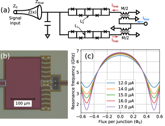
Figure. 1(a) shows a simplified diagram of the amplifier. The nonlinear inductance is composed of two rf-SQUID arrays arranged in parallel to form a compound SQUIDNaaman et al. (2019), with a total of unit cells. Each rf-SQUID consists of a junction with a critical current , and a linear inductance composed of two segments with inductance and one segment with inductance . The segments are shared between neighboring rf-SQUIDs, so that the structure as a whole forms a serpentine inductive spine of alternating and , bridged by Josephson junctions at each meander. We will refer to this structure as the ‘snake’, and to the amplifier as a whole as ‘snake-IMPA‘ or ‘SNIMPA’ for short. The parallel arrangement of the arrays enables us to flux-bias and pump the amplifier via a single superconducting split-coil spiral transformer as shown in the figure. The transformer primary coils are connected in parallel paths between the bias feedline and ground. The secondary coils are counter-wound to primarily couple the bias to the circulating current mode ( in the figure) of the compound SQUID loop formed by the two parallel portions of the snake (see Supplementary Material). The transformer mutual inductance is pH, and the self-inductance of the secondary coil is pH. Finally, the structure is shunted by a capacitor , and is connected to the signal port via a Klopfenstein taper as in Ref. Mutus et al., 2014. An optical micrograph of the shunt capacitor, compound snake-SQUID, and bias transformer is shown in Fig. 1(b).
The resonance frequency of the nonlinear circuit created by the capacitively-shunted snake is , where is given byNaaman et al. (2019, 2017) (see Supplementary Material)
| (1) |
, and is the equilibrium junction phase, which is dependent on the flux biasNaaman et al. (2019, 2017). is a stray inductance that includes a contribution from the bias transformer self-inductance. The calculated resonance frequency for typical circuit parameters is shown in Fig. 1(c) as a function of applied flux bias per junction (or per rf-SQUID) in the array.
To avoid hysteresis in the modulation curve, the snake must be designed such that . This means that, unlike a conventional dc-SQUID, the inductance of a snake-SQUID does not diverge at . Therefore has a limited tunability range compared to conventional JPAs, as seen in Fig. 1(c). We therefore choose the shunt capacitance such that the frequency tunability range overlaps the desired operating frequency of the amplifier, 4.5-5.0 GHz. The device is flux-pumped at frequency , which is twice the center frequency of the amplifier.
Here, we report on amplifiers having two design variants. The first, Design 1, has a nominal junction A and a shunt capacitance of pF, and the second, Design 2, has a nominal A and pF. Both designs have nominal snake inductances of pH and pH. From measurement of test junctions, we estimate that the actual critical current of the snake junctions is % lower than designed. The Klopfenstein taper that matches the low impedance SNIMPA resonator to the signal port is similar to that reported in Ref. Mutus et al., 2014, with a cutoff frequency of 2.6 GHz and a 50-section taper from to , resulting in a resonator loaded Q of about 4.5. The devices were built in a three-layer aluminum process with SiOx interlayer dielectrics and Al/AlOx/Al trilayer Josephson junctions. The first metal layer was used as a solid ground plane under the snake structure, and the upper two layers form the circuit elements of the amplifier (see Supplementary Material). In operation, the amplifiers’ dc flux bias amounts to approximately A carried in each of the bias transformer primary coils, well below the measured critical current of traces and vias in our process.
We have characterized the performance of the SNIMPA devices with a 54-qubit Sycamore processorArute et al. (2019). The processor consists of nine independent readout lines, each with six frequency-multiplexed readout resonators occupying a 4.6-4.8 GHz band. Each readout line has an on-chip Purcell filterJeffrey et al. (2014), and is connected to a SNIMPA amplifier through four circulators. The readout resonators and Purcell filters were designed with a target resonator ringdown time of ns. The readout lines are labeled A through I; lines A, C, E, and G had a SNIMPA with Design 1, and the rest had Design 2. All SNIMPA were packaged with a magnetic shield. In a separate cooldown, all readout lines were outfitted with standard dc-SQUID based IMPA, whose performance we use as a baseline for comparison.
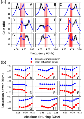
Figure. 2(a) shows the SNIMPA gain vs signal frequency (blue lines) on all readout lines as labeled. Each curve was measured at low power with a vector network analyzer, after manual tuneup of the amplifier’s flux bias, pump frequency, and pump power. The frequencies of the readout resonators associated with each line are indicated by the vertical dashed lines (red). All amplifiers achieve gains greater than 15 dB over the entire readout band, and most resonators can be read out with a gain exceeding 20 dB. The gain profile is not Lorentzian; this is because the complex impedance seen by the SNIMPA nonlinear resonator varies over the amplifier bandMutus et al. (2014). The multi-peak response is commonly seen in wider band parametric amplifiersMutus et al. (2014); Grebel et al. (2021); Ranzani et al. (2022), but impedance matching network synthesis techniques could be used to achieve better control of gain flatness and rippleNaaman and Aumentado (2022).
For the purpose of the present experiments we were focused on isolated qubit readout performance. In some cases, we allowed the center frequency of the amplifier to reside within the resonator band (e.g. line H). In simultaneous multi-qubit readout with degenerate parametric amplifiers, in which the signal (at frequency ) and idler (at ) share the same physical circuit, this can cause interference between a signal from one of the resonators and an idler generated by the readout of another. Therefore, in simultaneous multi-qubit readout, the pump should be tuned such that all readout resonator frequencies reside either below or above , meaning that only half the bandwidth is usefully available in practice.
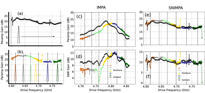
Figure 2(b) shows the input (squares) and output (circles) saturation power (1-dB gain compression) of each of the amplifiers, as a function of absolute signal detuning from the amplifier center frequency (half the pump frequency, ). The crosses in Fig. 2(a) denote the frequency and gain at which each point was measured. For this experiment we calibrate the signal power at the processor reference plane using ac Stark shift of the processor qubits. We first measure the dispersive shift (where and are the dressed resonance frequencies), and the resonator decay rate spectroscopically for each qubit in our processor. From the ac Stark shift, which is given (in the linear regime) by , we extract , the average resonator photon occupation for a given combination of resonator drive power and frequencySchuster et al. (2007). From the measured values of and we calculate the microwave power impinging on the resonatorVijay et al. (2012). Repeating this measurement at varying powers from the room-temperature signal generator allows us to calibrate the power delivered to the chip as a function of signal generator power. Figure 2(b) shows that the SNIMPA consistently achieve output saturation powers in the dBm to dBm range, up to 20 dB higher than our standard dc-SQUID based IMPA. While output saturation power, being ideally gain-independent, is the more fundamental quantity, the figure also reports the input saturation power to allow a more direct comparison with the bulk of the existing literature.
We do not measure the amplifier added noise directly. Instead, we focus on the overall readout efficiencyBultink et al. (2018), , which is a more relevant metric from a systems performance perspective (see Supplementary Material). Readout efficiency encapsulates all microwave losses, , between the readout resonators and the SNIMPA, as well as the noise temperature of the SNIMPA itself, , and the effective noise temperature, , of the cryogenic HEMT amplifier and the rest of the measurement chain following the SNIMPA. Since our amplifiers are operated in a phase preserving mode, the maximum possible efficiency is .
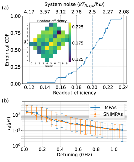
Fig. 3(a) shows the measured readout efficiency for all qubits in our Sycamore processor. The empirical cumulative distribution function of these data is shown in the main plot, with a median of corresponding to a system noise temperature of mK. The inset shows how these efficiencies are distributed across the qubit grid.
We measure the readout efficiency, , and signal-to-noise ratio (SNR) gain, , as a function of SNIMPA power gain, , for all qubits in our processor:
| (2) | ||||
| (3) |
where is the quantum noise at the readout frequency, and fit the data with both equations simultaneously. Since these fits cannot separate out contributions from and , we have to fix one of these parameters. If the SNIMPA were quantum limited and we fix , then fits to our data suggest an average insertion loss of , or dB, between the processor chip and the SNIMPA.
Independent, cryogenically calibratedWang et al. (2021) measurements of individual component losses (circulators and wiring) add up to a minimum of dB of loss between the processor chip and the SNIMPA (see Supplementary Material). If we therefore fix ( dB) in the fits, then we can extract a maximum SNIMPA noise temperature, K, roughly higher than the quantum limit. A cryogenically calibrated measurement of a representative integrated readout assembly shows an insertion loss that varies between dB and dB over the readout band (see Supplementary Material). These data put bounds on the average noise performance of the SNIMPA, as deployed, in the context of qubit readout of our processor. The data suggest that after accounting for component losses, the measured efficiencies are consistent with near quantum limited noise performance of the SNIMPA amplifiers.
A potential concern with the SNIMPA is that the snake inductor could increase back action on the qubit, compared to the standard dc-SQUID based amplifiers. This could be due to coupling of noise photons through the large bias transformer, pump leakage to the signal line, or the generation of spurious signals or noise during amplification. Figure 3(b) shows qubit dephasing time, , as measured using the CPMG (Carr-Purcell-Meiboom-Gill) methodBylander et al. (2011), vs qubit detuning away from their flux-insensitive point. The data, representing the median over all qubits in the processor, compare the performance measured with the SNIMPAs (orange) to that measured in a separate cooldown of the same processor with the standard IMPA amplifiers (blue). The data indicate that the SNIMPA have no adverse effect on qubit dephasing as compared to our standard dc-SQUID based amplifiers.
Finally, we performed multi-tone experiments to test the SNIMPA performance in an emulated simultaneous multi-qubit readout scenario. We chose to do so, instead of directly characterizing multi-qubit readout fidelity, to avoid confounding qubit-related physics at high readout powersSank et al. (2016) that can mask the underlying performance of the amplifiers. As a baseline, we first measure the amplifier signal power gain and SNR improvement (SNR gain) as a function of frequency with a single (‘isolated’), weak readout tone (approximately dBm), as shown in Fig. 4(a). We then repeat the measurement with five additional tones (emulating the six-qubit multiplexed readout in the Sycamore processorArute et al. (2019)), and with each tone having 10 dB higher power, as illustrated in Fig. 4(b). Here, each one of the readout tones is swept in turn across its corresponding frequency band (respective color) and we measure the signal and SNR gains while the others tones are on and are kept at the fixed frequencies indicated by the respective vertical dashed lines. Figure 4(c) and (d) show the gain and SNR improvement, respectively, for our standard dc-SQUID based IMPA, clearly showing a degradation in both quantities in the multi-tone experiment (color) compared with the low-power baseline (black). In contrast, no such degradation is observed with the SNIMPA, as shown in Fig. 4(e)-(f). In fact, we found it difficult to drive the SNIMPA to saturation with our standard readout electronics setup. These experiments demonstrate that the SNIMPA’s high saturation power offers sufficient headroom in a multi-qubit readout situation to enable more efficient readout multiplexing with higher number of qubits read-out simultaneously per channel. The SNIMPA can also accommodate higher power per readout tone, which may be required for high-fidelity, fast readout with greater qubit-resonator detuning or weaker qubit-resonator coupling.
In summary, we have demonstrated impedance matched Josephson parametric amplifiers with saturation powers up to two orders of magnitude higher than their standard dc-SQUID based counterparts. By combining an rf-SQUID array nonlinear element with an impedance matching taper, these amplifiers achieve sufficient instantaneous bandwidth to support 6:1 frequency-multiplexed readout of our Sycamore processors. We have measured a median readout efficiency of 20%, extracted an upper bound for the SNIMPA noise temperature at around 60% over the quantum limit, and found no excess amplifier-related dephasing compared to our standard IMPA-based setup.
I Supplementary Material
See supplementary material for details on the derivation of the snake inductance, transformer design, efficiency measurement, and loss budget estimates.
References
- Wallraff et al. (2005) A. Wallraff, D. Schuster, A. Blais, L. Frunzio, J. Majer, M. Devoret, S. Girvin, and R. Schoelkopf, “Approaching unit visibility for control of a superconducting qubit with dispersive readout,” Phys. Rev. Lett. 95, 060501 (2005).
- Sank et al. (2016) D. Sank, Z. Chen, M. Khezri, J. Kelly, R. Barends, B. Campbell, Y. Chen, B. Chiaro, A. Dunsworth, A. Fowler, et al., “Measurement-induced state transitions in a superconducting qubit: Beyond the rotating wave approximation,” Physical review letters 117, 190503 (2016).
- Vijay, Slichter, and Siddiqi (2011) R. Vijay, D. Slichter, and I. Siddiqi, “Observation of quantum jumps in a superconducting artificial atom,” Physical review letters 106, 110502 (2011).
- Roch et al. (2012) N. Roch, E. Flurin, F. Nguyen, P. Morfin, P. Campagne-Ibarcq, M. H. Devoret, and B. Huard, “Widely tunable, nondegenerate three-wave mixing microwave device operating near the quantum limit,” Phys. Rev. Lett. 108, 147701 (2012).
- Mutus et al. (2013) J. Mutus, T. White, E. Jeffrey, D. Sank, R. Barends, J. Bochmann, Y. Chen, Z. Chen, B. Chiaro, A. Dunsworth, et al., “Design and characterization of a lumped element single-ended superconducting microwave parametric amplifier with on-chip flux bias line,” Appl. Phys. Lett. 103, 122602 (2013).
- Aumentado (2020) J. Aumentado, “Superconducting parametric amplifiers: The state of the art in Josephson parametric amplifiers,” IEEE Microwave magazine 21, 45–59 (2020).
- Arute et al. (2019) F. Arute, K. Arya, R. Babbush, D. Bacon, J. C. Bardin, R. Barends, R. Biswas, S. Boixo, F. G. Brandao, D. A. Buell, et al., “Quantum supremacy using a programmable superconducting processor,” Nature 574, 505–510 (2019).
- Mutus et al. (2014) J. Mutus, T. White, R. Barends, Y. Chen, Z. Chen, B. Chiaro, A. Dunsworth, E. Jeffrey, J. Kelly, et al., “Strong environmental coupling in a Josephson parametric amplifier,” Appl. Phys. Lett. 104, 263513 (2014).
- Roy et al. (2015) T. Roy, S. Kundu, M. Chand, A. Vadiraj, A. Ranadive, N. Nehra, M. P. Patankar, J. Aumentado, A. Clerk, and R. Vijay, “Broadband parametric amplification with impedance engineering: Beyond the gain-bandwidth product,” Applied Physics Letters 107, 262601 (2015).
- Duan et al. (2021) P. Duan, Z. Jia, C. Zhang, L. Du, H. Tao, X. Yang, L. Guo, Y. Chen, H. Zhang, Z. Peng, et al., “Broadband flux-pumped Josephson parametric amplifier with an on-chip coplanar waveguide impedance transformer,” Applied Physics Express 14, 042011 (2021).
- Naaman and Aumentado (2022) O. Naaman and J. Aumentado, “Synthesis of parametrically coupled networks,” PRX Quantum 3, 020201 (2022).
- Frattini et al. (2018) N. Frattini, V. Sivak, A. Lingenfelter, S. Shankar, and M. Devoret, “Optimizing the nonlinearity and dissipation of a SNAIL parametric amplifier for dynamic range,” Physical Review Applied 10, 054020 (2018).
- Naaman et al. (2019) O. Naaman, D. G. Ferguson, A. Marakov, M. Khalil, W. F. Koehl, and R. J. Epstein, “High saturation power Josephson parametric amplifier with GHz bandwidth,” in 2019 IEEE MTT-S International Microwave Symposium (IMS) (2019) pp. 259–262.
- Macklin et al. (2015) C. Macklin, K. O’brien, D. Hover, M. Schwartz, V. Bolkhovsky, X. Zhang, W. Oliver, and I. Siddiqi, “A near–quantum-limited Josephson traveling-wave parametric amplifier,” Science 350, 307–310 (2015).
- O’Brien et al. (2014) K. O’Brien, C. Macklin, I. Siddiqi, and X. Zhang, “Resonant phase matching of Josephson junction traveling wave parametric amplifiers,” Phys. Rev. Lett. 113, 157001 (2014).
- Bockstiegel et al. (2014) C. Bockstiegel, J. Gao, M. Vissers, M. Sandberg, S. Chaudhuri, A. Sanders, L. Vale, K. Irwin, and D. Pappas, “Development of a broadband NbTiN traveling wave parametric amplifier for MKID readout,” J. Low. Temp. Phys. , 1–7 (2014).
- Eom et al. (2012) B. H. Eom, P. K. Day, H. G. LeDuc, and J. Zmuidzinas, “A wideband, low-noise superconducting amplifier with high dynamic range,” Nat. Phys. (2012).
- Esposito et al. (2021) M. Esposito, A. Ranadive, L. Planat, and N. Roch, “Perspective on traveling wave microwave parametric amplifiers,” Applied Physics Letters 119, 120501 (2021).
- Peng et al. (2022) K. Peng, M. Naghiloo, J. Wang, G. D. Cunningham, Y. Ye, and K. P. O’Brien, “Floquet-mode traveling-wave parametric amplifiers,” PRX Quantum 3, 020306 (2022).
- Barends et al. (2014) R. Barends, J. Kelly, A. Megrant, A. Veitia, D. Sank, E. Jeffrey, T. White, J. Mutus, A. Fowler, B. Campbell, et al., “Superconducting quantum circuits at the surface code threshold for fault tolerance,” Nature 508, 500–503 (2014).
- Jeffrey et al. (2014) E. Jeffrey, D. Sank, J. Mutus, T. White, J. Kelly, R. Barends, Y. Chen, Z. Chen, B. Chiaro, A. Dunsworth, et al., “Fast accurate state measurement with superconducting qubits,” Phys. Rev. Lett. 112, 190504 (2014).
- Naaman et al. (2017) O. Naaman, J. Strong, D. Ferguson, J. Egan, N. Bailey, and R. Hinkey, “Josephson junction microwave modulators for qubit control,” Journal of Applied Physics 121, 073904 (2017).
- Grebel et al. (2021) J. Grebel, A. Bienfait, É. Dumur, H.-S. Chang, M.-H. Chou, C. Conner, G. Peairs, R. Povey, Y. Zhong, and A. Cleland, “Flux-pumped impedance-engineered broadband Josephson parametric amplifier,” Applied Physics Letters 118, 142601 (2021).
- Ranzani et al. (2022) L. Ranzani, G. Ribeill, B. Hassick, and K. C. Fong, “Wideband josephson parametric amplifier with integrated transmission line transformer,” arXiv preprint arXiv:2208.02331 (2022).
- Schuster et al. (2007) D. I. Schuster, A. A. Houck, J. A. Schreier, A. Wallraff, J. M. Gambetta, A. Blais, L. Frunzio, J. Majer, B. Johnson, M. H. Devoret, S. M. Girvin, and R. J. Schoelkopf, “Resolving photon number states in a superconducting circuit,” Nature 445, 515–518 (2007).
- Vijay et al. (2012) R. Vijay, C. Macklin, D. Slichter, S. Weber, K. Murch, R. Naik, A. N. Korotkov, and I. Siddiqi, “Stabilizing Rabi oscillations in a superconducting qubit using quantum feedback,” Nature 490, 77–80 (2012).
- Bultink et al. (2018) C. C. Bultink, B. Tarasinski, N. Haandbæk, S. Poletto, N. Haider, D. Michalak, A. Bruno, and L. DiCarlo, “General method for extracting the quantum efficiency of dispersive qubit readout in circuit QED,” Applied Physics Letters 112, 092601 (2018).
- Wang et al. (2021) H. Wang, S. Singh, C. McRae, J. Bardin, S. Lin, N. Messaoudi, A. Castelli, Y. Rosen, E. Holland, D. Pappas, et al., “Cryogenic single-port calibration for superconducting microwave resonator measurements,” Quantum Science and Technology 6, 035015 (2021).
- Bylander et al. (2011) J. Bylander, S. Gustavsson, F. Yan, F. Yoshihara, K. Harrabi, G. Fitch, D. G. Cory, Y. Nakamura, J.-S. Tsai, and W. D. Oliver, “Noise spectroscopy through dynamical decoupling with a superconducting flux qubit,” Nature Physics 7, 565–570 (2011).