Large Impact of Small Vertex Cuts on the Mechanics of Origami Bellows
Abstract
For origami structures, perforating or cutting slits along creases is an effective method to define fold lines and alleviate stress concentrations at vertices. In this letter we show numerically and experimentally that for non-rigid-foldable origami bellows (e.g. Miura-ori, Kresling patterns) the introduction of small cut-outs at the vertices results in up to an order of magnitude reduction of the bellows’ stiffness under axial compression. Further, the cut-outs at vertices impact the nonlinear response, e.g. the position and magnitude of a force limit point and presence of bistable configurations. As the origami bellows are not rigid foldable, an axial compression will necessarily result in facet deformations; the small cut-outs at the vertices are found to provide an unexpectedly large stress alleviation, resulting in disproportionate changes in mechanical properties of the bellows. In order to accurately model the mechanics of origami bellows, such manufacturing details must therefore be captured accurately. Lastly, introducing vertex cut-outs can be offered as a novel approach to tailoring the stiffness of non-rigid foldable origami structures.
Keywords origami origami bellows non-rigid foldable origami modelling
1 Introduction
Origami, a traditional paper folding art, is a mapping of a flat sheet material to a three-dimensional object by folding along defined creases. Due to its inherent kinematics, programmable stiffness and self-foldability, origami has become an active research topic in fields such as deployable structures (Wang et al., 2022; Dang et al., 2022), robotics (Balkcom and Mason, 2008; Jeong and Lee, 2018), architected materials (Silverberg et al., 2014; Li et al., 2019) and energy absorption devices (Ma, 2011; Ming et al., 2021). Origami bellows are formed by folding origami patterns into closed cylindrical structures. The bellows can be classified according to their crease patterns, including the well-known Miura-ori and Kresling patterns (Reid et al., 2017). Origami bellows have been shown to provide a rich and tailorable nonlinear response, and have been explored for applications such as inflatable booms (Schenk and Guest, 2013), binary switches (Masana et al., 2020), mechanical memory(Jules et al., 2022), and soft robotics (Pagano et al., 2017; Chen et al., 2020; Wu et al., 2021).
For many applications, the mechanical properties of the origami bellows must be predicted accurately to achieve the desired functionality. Although multi-stability of the bellows can be predicted geometrically (Reid et al., 2017), most bellows are not rigid-foldable (Tachi, 2009) and the facet deformations must thus be captured when modelling their folding motion. A common simplifying assumption is that fold lines remain straight, allowing the origami bellows to be modelled analytically and numerically using axial bar elements placed along the fold lines of triangulated patterns (Guest and Pellegrino, 1996; Zhai et al., 2018). A revised model of the Kresling bellows also accounts for kinking of the folds observed in experiments (Masana and Daqaq, 2019). More general bar-and-hinge models simulate in-plane stretching using bar elements while capturing folding and out-of-plane bending of facets using rotational hinges (Schenk and Guest, 2011; Filipov et al., 2017; Liu and Paulino, 2018). This method has been shown to be effective in simulating Miura-ori sheets (Liu and Paulino, 2017), Miura–ori tubes (Grey et al., 2019), etc. In order to capture more detail and increase modelling fidelity the Finite Element Method (FEM) is commonly used (Moshtaghzadeh et al., 2022; Shen et al., 2022). Various researchers also focused on the modelling of fold lines. For instance, Shen et al. (Shen et al., 2021) replaced the crease area by hinge connectors with an equivalent constitutive model based on numerical simulations, whereas Jules et al. (Jules et al., 2019) formulated analytical expressions for fold stiffness based on experiments. Hernandez et al. (Hernandez et al., 2016) introduced smooth folds in origami structures, allowing for the analysis of origami structures using shell representations for the folds.
Origami engineers and researchers may introduce holes at vertices to avoid large stress concentrations or perforate the fold lines to define a crease; their effects on the mechanics of origami structures have also been investigated. For rigid-foldable origami such as the Tachi-Miura Polyhedron (Yasuda et al., 2013) and the Miura-ori tube (Grey, 2021), small vertex cuts show minimal influence on the structural stiffness. In contrast, for non-rigid origami, the impact of cuts may be significant. For instance, Yu et al. (Yu et al., 2021) identified that cutting a hole in a folded elastic disk could significantly impact the mechanical response, for example eliminating bistability. Hwang (Hwang, 2021) studied the impact of offset slots along the crease line on the mechanical properties of Kresling pattern origami bellows. They found that the length and spacing of the slots were significant factors in the nonlinear response, including presence of instability.
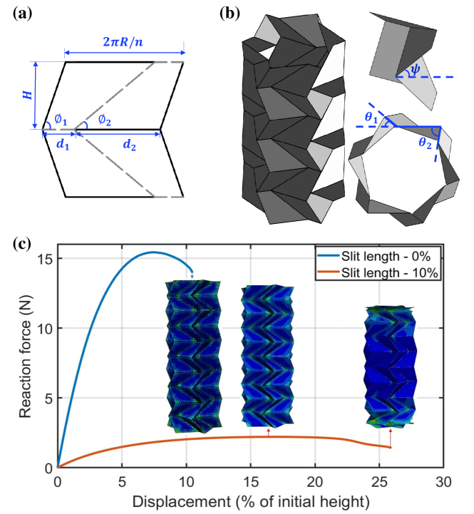
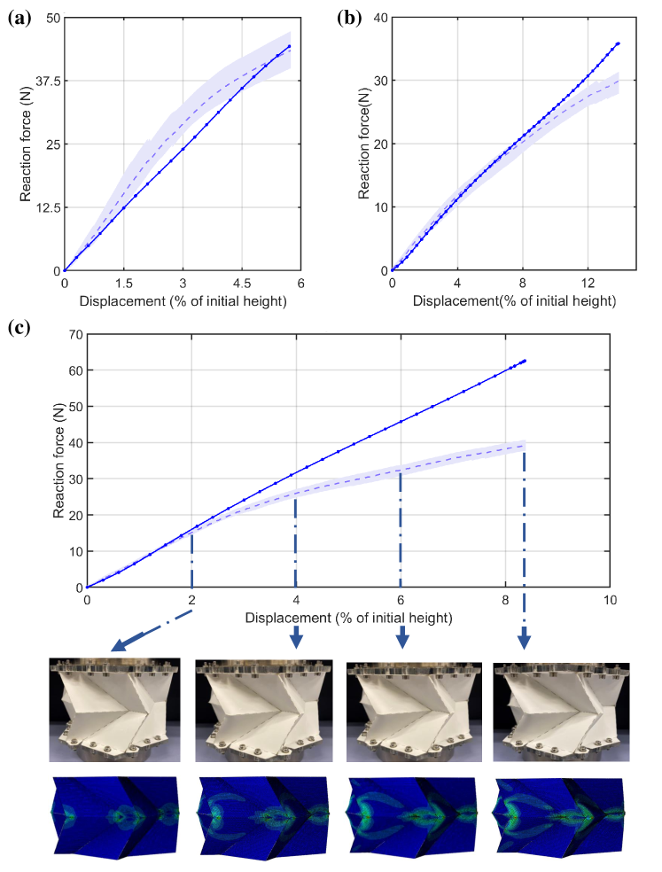
For non-rigid foldable origami such as origami bellows, detailed numerical models have thus been found to be essential since small changes and imperfections may significantly influence the mechanical properties (Ming et al., 2021; Yu et al., 2021; Hwang, 2021). In our work, we introduce small cuts (or slits) at the vertices and study the impact on the mechanics of origami bellows. As an illustrative example, consider the response of the Miura-ori bellows shown in Fig. 1. The loading boundary condition constrains the top/bottom ends to remain planar, but allows the cross-section to expand or contract during compression. As shown in Fig. 1(c), for the bellow without vertex cuts the response is nonlinear and the deformation is nominally uniform along the length of the bellow. Introducing slits at the vertices (slit length = of fold line) results in significant changes in response. Initially the deformation is uniform along the bellows, but this localises at the boundaries after reaching the load limit point. Moreover, the axial stiffness shows a decrease of over 90%. This preliminary result shows an unexpectedly large impact of small slits at the vertices; a total reduction of 20% of the fold line length results in a reduction of 90% in axial stiffness. Therefore, it is essential to investigate the influence of the vertex cuts on the mechanical response of origami bellows.
2 Numerical and Experimental Methods
Our aim is to model the axial compression of origami bellows. In addition to the pattern geometry and material properties, the bellows’ full mechanical response depends on the loading boundary conditions in combination with the number of layers, , as evidenced by the localisation of deformations observed in Fig. 1(c). Under the selected boundary conditions, the initial deformation is nominally uniform along the length of the bellows; for simplicity we therefore study a single layer () to reveal the impact of the vertex slit length on the mechanical response of the bellows.
2.1 Numerical Method
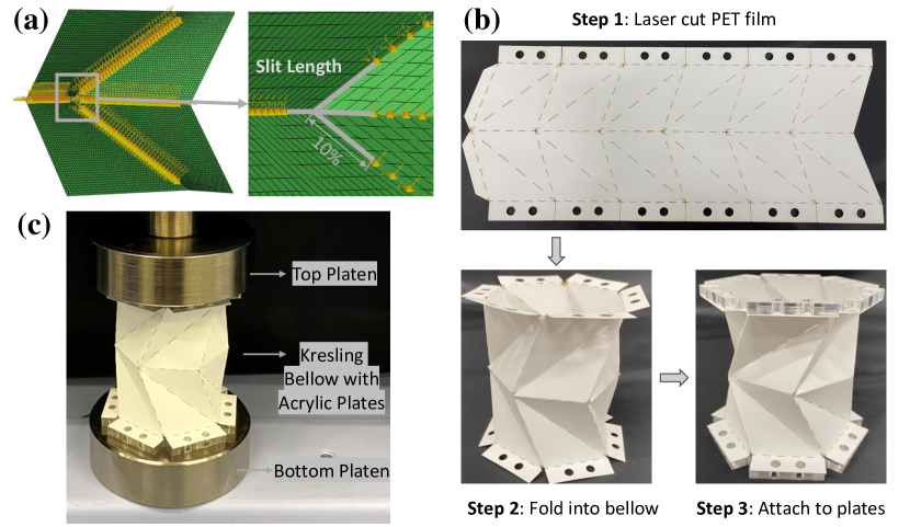
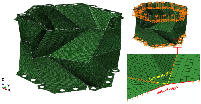
The origami bellows are modelled using the commercial finite element software Abaqus Dassault Systèmes (2018) in order to capture the details of the vertex cuts. The facets of Miura-ori bellows are meshed using quadrilateral shell elements (S4R) while triangular shell elements (S3R) are utilized for Kresling bellows. All simulations are geometrically nonlinear. After a mesh sensitivity study (Appendix C) a mesh size of elements per facet was selected. Hinge connectors (CONN3D2 elements) with zero width and constant torsional stiffness are used to connect pairs of nodes on adjacent facets to represent the fold stiffness. Adjacent to each vertex, several pairs of mesh nodes along the fold lines remain unconnected to represent the vertex cuts; see Fig. 2(a). The size of the vertex cuts is quantified as % of the fold line length. For bellows without slits, join connectors are used to connect the vertex at two adjacent facets.
Thermoplastic Polyethylene Terephthalate (PET) film is selected as the material for the bellows; the Young’s modulus, Poisson’s ratio and thickness are MPa, = 0.43, and mm, respectively. The fold stiffness per unit length of fold is taken to be N/rad based on experimental data (Grey et al., 2019; Grey, 2021; Grey et al., 2021). The fold stiffness depends on material properties as well as the crease type and manufacturing technique (e.g. perforation, scoring, hemming). However, our study shows that the compressive stiffness of the bellows is not sensitive to changes in (Appendix C). Note that the total stiffness along each fold line in the numerical models is kept constant, by increasing the fold stiffness proportionally. In folding a bellow from a flat sheet, self-stress is introduced at the fold lines, which may in turn affect its mechanical properties (Grey et al., 2020). The choice of PET has the additional benefit of being able to anneal the material to relax initial stresses at the fold lines Sargent et al. (2019). In our modelling, all fold lines are assumed to be stress free in the initial configuration.
To be representative of one layer in a multi-layer bellow, the loading boundary conditions are selected to allow free expansion/contraction of the bellow’s cross-section during axial compression. The top and bottom of the layer are further constrained to remain planar, and a compressive displacement of 30% of total height of the bellow is applied along the bellow’s cylindrical axis. All other degrees of freedom on the top and bottom cross-sections are left unconstrained. This boundary condition will be referred to as “Flexible BC”. In replicating the experimental results, the boundary conditions are changed to fix all translational degrees of freedom at the top/bottom cross-sections of the bellows; we refer to this as “Fixed BC”.
2.2 Experimental Method
The numerical simulations of the Miura-ori and Kresling bellows are compared against experimental measurements, for samples with vertex cuts of 0%, 5%, 10% and 20% of the fold line length. The bellows are folded from PET sheets (PicoFilm Tearproof Colour Laser Film) with a thickness of mm. The crease patterns are prepared using a Trotec Speedy 360 laser cutter. First, the pattern is cut out and fold lines are perforated with cuts of length CT = 1/9 of the fold line length (excluding slit length) spaced evenly at CT intervals to define the creases; see Fig. 2(b). For a slit length = 0% of the fold line there is no perforation at the vertices. Next, the crease pattern is folded to form a single-layer bellow, which is closed and sealed using double-sided tape on the end tabs. If the bellow is flat-foldable, it is compressed to the flat state and allowed to spring back to the initial stable configuration. Finally, the top and bottom of the bellow are attached to acrylic plates using double-sided tape and bolts (for Miura-ori bellows). The experimental set-up thus constrains all displacements at the top and bottom cross-section of the bellows, whilst allowing folding along the fold lines. Once assembled, the bellows are compressed using a Shimadzu universal testing machine with 1 kN load cell at a speed of 2 mm/min; see Fig. 2(c). Three samples are manufactured and tested for each vertex cut size, and the averaged results are presented in Fig. 3.
3 Results and Discussion
3.1 Experimental Validation of Numerical Models
The numerical and experimental results for Kresling and Miura-ori bellows with different vertex slit lengths are presented in Fig. 3. It is evident that the vertex cuts significantly impact the nonlinear response of the origami bellows; in particular, we highlight the sensitivity of the bellows’ compressive stiffness to the introduction of a small vertex cut. The compressive stiffness is calculated using a least-squares fit over displacements from % of the initial height.
The experimental and numerical results for the Kresling bellows match well, and the relative error for the compressive stiffness is within 20% (Appendix E). The discrepancy between the simulation and the experiment can be attributed to factors such as self-weight, self-stress and imperfections which were not modelled; further, the slits along the fold lines at the top and the bottom of the bellows where the boundary condition is applied are not captured. Moreover, the deformations also show a good qualitative match. Figure 3(b) shows the deformed configurations for a Kresling bellow with a slit length = 5%. The experimentally observed localised kinking of the fold lines near the vertices is accurately captured in the numerical models.
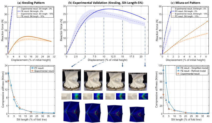
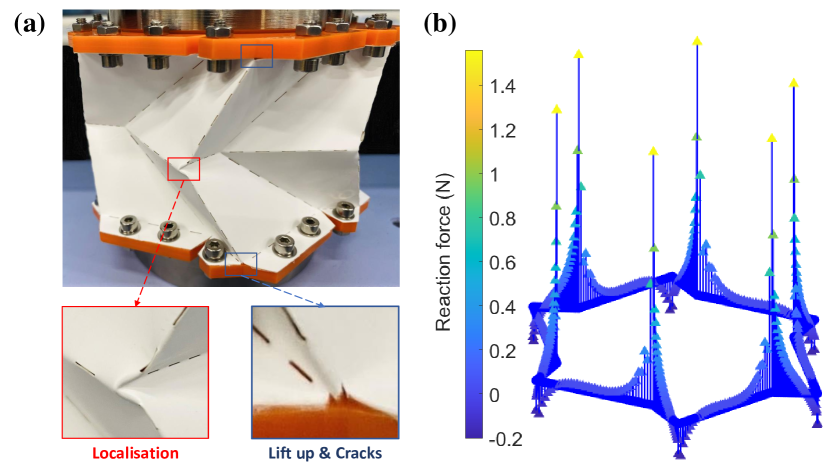
For the Miura-ori bellows, discrepancies in the compressive stiffness were found for small vertex cuts (up to 5% of the fold length), with the experimental results being much more compliant than the numerical simulations. Upon closer inspection, as highlighted in Fig. 4(a), it was noticed that at certain vertices the bellows would “lift up” from the end plates, resulting in more compliant boundary conditions than those imposed in the simulations. This is the result of unexpected tensile reaction forces (i.e. the bellows pulling away from the plates) at these vertices, despite the bellows being loaded in compression; see Fig. 4(b). To capture this effect, a more refined FE model included the details of the end tabs and enabled “lift up” at these vertices (see Appendix D for further details). As shown in Fig. 3(c) the refined model provides a good match for slit length = 5% (and greater) with a relative error within 20%, but not for slit length = 0% of the fold line, where the predicted stiffness is approximately twice the experimental value. It is hypothesised that small tears and cracks (see Fig. 4(a)) generated during the manufacturing or folding process will propagate during the compression procedure, serving as slits, and thus leading to a further reduction in stiffness. The cracks are randomly distributed at several fold lines and are approximately mm (% of the fold line) in length; the measured compressive stiffness for slit length = 0% of the fold line falls between the numerical results of slit length = 0% and 2.5% of the fold line (refined FE model), which supports this assumption.
Overall, the numerical results show a good match with experimental results, allowing us to explore the nonlinear response of origami bellows further.
3.2 Effect of Vertex Slit Length
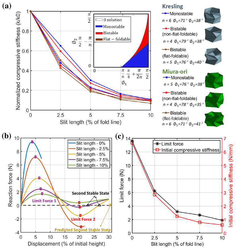
The experimental and numerical results show that the compressive stiffness of the Kresling and Miura-ori bellows decreases sharply when the vertex slit length increases from 0% to 10% of the fold line length. This result is found to hold for a wide range of Kresling and Miura-ori bellows geometries. Figure 5(a) shows the normalised axial stiffness vs vertex slit length for bellows patterns selected from across the feasible geometric design space (Reid et al., 2017). This includes origami bellows that are monostable, bistable flat-foldable and bistable non-flat-foldable. Introducing slits at vertices of merely 2.5% of the fold line length will lead to an almost 50% decrease in stiffness compared to models with no slits; increasing the cut-out to 10% of the fold line length will lead to a stiffness reduction by an order of magnitude.
The introduction of vertex cuts not only affects the compressive stiffness of the origami bellows, but also their nonlinear response. The force-displacement response of a bistable, non-flat-foldable Kresling model is shown in Fig. 5(b). For increasing slit length, the magnitude of the force limit point decreases and the location of the second stable state changes. What is more, for a slit length of 10% of the fold line, the second stable point disappears, thus eliminating the predicted bistability. Miura-ori bellows display a similar change in magnitude and location of the force limit point. For example, the force limit point of a flat-foldable bistable Miura-ori bellow with varying vertex cut length is shown in Fig. 5(c), and it is compared against the corresponding initial compressive stiffness. The trends of both curves is the same: the limit force also shows a decrease of over an order of magnitude when the slit length increases to 10% of the fold line.
In summary, the introduction of a small vertex cut has been found to have an unexpected and disproportionate effect on the mechanics of origami bellows. The reduction in stiffness of the bellows is much greater than could be explained simply by the reduction in fold line length (and thus total fold stiffness). This suggests that the effect is due to the fact that the bellows are not rigid-foldable, and an axial compression therefore introduces in-plane loads in the facets. This hypothesis is supported by the analysis of a rigid-foldable Miura-ori unit cell (Appendix B) as well as previous work where vertex cut-outs were used in rigid-foldable Miura-ori tubes and sheets (Grey et al., 2019; Grey, 2021). Nonetheless, the sensitivity to the vertex slit length remains unexpectedly large. Hwang (Hwang, 2021) described a similar effect, with a significant change in stiffness and nonlinear response of Kresling bellows as a result of perforations along the fold line. In that work, however, the shear stiffness of the fold line is drastically reduced as a result of the perforation pattern, which could account for the change in mechanical properties of the bellows.
4 Conclusions
In this letter we investigate the impact of introducing vertex cuts in non-rigid foldable origami bellows. The mechanical response of the bellows (e.g. axial compressive stiffness, nonlinear response) is found to be highly sensitive to the size of the cut-outs; the numerical results were validated against experiments. This effect is robust to different bellows patterns such as the Miura-ori and Kresling, as well as modelling approaches for the fold lines such as torsion springs and smooth folds (the implementation is discussed in Appendix F). This phenomenon has not been reported in previous studies, and the impact of cut-outs is not present in rigid-foldable patterns such as Miura-ori sheets.
Specifically, increasing the vertex slit length results in a disproportionate decrease in compressive stiffness of the origami bellows. As the slit length increases from 0 to 2.5% of the fold line, the compressive stiffness drops by over 50%. Once the slit length increases to 10%, the stiffness decreases by an order of magnitude compared to the original bellows. The magnitude and location of force limit points in the nonlinear response are similarly impacted by the size of the vertex cut. Moreover, the vertex cut also affects the second stable state and may lead to the disappearance of the predicted bistability. In the analysis of Miura-ori bellows, another interesting effect was observed: for a bellows under compression, a tensile reaction force was found at certain vertices, resulting in the bellows pulling away from the end plates at these locations.
In conclusion, for non-rigid foldable origami bellows where folding also induces facet deformations, it is critical to accurately model the cut-outs at vertices, since it could lead to a significant change in mechanical properties, such as axial stiffness, limit force and stability. The importance of capturing particular details is also evidenced by recent work on perforated fold lines (Hwang, 2021). These results may have wider implications for the applicability of reduced-order models (such as bar and hinge models), which cannot capture such details, for the analysis of non-rigid-foldable origami. On the other hand, tailoring the vertex slit length may provide an alternative method to manipulate stiffness and stability of origami bellows, and can therefore offer a promising approach to designing mechanical memory systems, graded-stiffness structures, etc.
Acknowledgement
Mengzhu Yang is supported through a China Scholarship Council (CSC)–University of Bristol joint scholarship.
References
- Wang et al. [2022] Sen Wang, Yinghao Gao, Hailin Huang, Bing Li, Hongwei Guo, and Rongqiang Liu. Design of deployable curved-surface rigid origami flashers. Mechanism and Machine Theory, 167:104512, 2022.
- Dang et al. [2022] Xiangxin Dang, Fan Feng, Paul Plucinsky, Richard D James, Huiling Duan, and Jianxiang Wang. Inverse design of deployable origami structures that approximate a general surface. International Journal of Solids and Structures, 234:111224, 2022.
- Balkcom and Mason [2008] Devin J Balkcom and Matthew T Mason. Robotic origami folding. The International Journal of Robotics Research, 27(5):613–627, 2008.
- Jeong and Lee [2018] Donghwa Jeong and Kiju Lee. Design and analysis of an origami-based three-finger manipulator. Robotica, 36(2):261–274, 2018.
- Silverberg et al. [2014] Jesse L Silverberg, Arthur A Evans, Lauren McLeod, Ryan C Hayward, Thomas Hull, Christian D Santangelo, and Itai Cohen. Using origami design principles to fold reprogrammable mechanical metamaterials. science, 345(6197):647–650, 2014.
- Li et al. [2019] Suyi Li, Hongbin Fang, Sahand Sadeghi, Priyanka Bhovad, and Kon-Well Wang. Architected origami materials: how folding creates sophisticated mechanical properties. Advanced materials, 31(5):1805282, 2019.
- Ma [2011] Jiayao Ma. Thin-walled tubes with pre-folded origami patterns as energy absorption devices. PhD thesis, University of Oxford, 2011.
- Ming et al. [2021] Shizhao Ming, Zhibo Song, Caihua Zhou, Tong Li, Kaifan Du, Shengli Xu, and Bo Wang. The energy absorption of long origami-ending tubes with geometrical imperfections. Thin-Walled Structures, 161:107415, 2021.
- Reid et al. [2017] Austin Reid, Frederic Lechenault, Sergio Rica, and Mokhtar Adda-Bedia. Geometry and design of origami bellows with tunable response. Physical Review E, 95(1):013002, 2017.
- Schenk and Guest [2013] Mark Schenk and Simon D Guest. Geometry of miura-folded metamaterials. Proceedings of the National Academy of Sciences, 110(9):3276–3281, 2013.
- Masana et al. [2020] R Masana, S Khazaaleh, H Alhussein, RS Crespo, and MF Daqaq. An origami-inspired dynamically actuated binary switch. Applied Physics Letters, 117(8):081901, 2020.
- Jules et al. [2022] Théo Jules, Austin Reid, Karen E Daniels, Muhittin Mungan, and Frédéric Lechenault. Delicate memory structure of origami switches. Physical Review Research, 4(1):013128, 2022.
- Pagano et al. [2017] Alexander Pagano, Tongxi Yan, Brian Chien, A Wissa, and S Tawfick. A crawling robot driven by multi-stable origami. Smart Materials and Structures, 26(9):094007, 2017.
- Chen et al. [2020] Wei-Hsi Chen, Shivangi Misra, Yuchong Gao, Young-Joo Lee, Daniel E Koditschek, Shu Yang, and Cynthia R Sung. A programmably compliant origami mechanism for dynamically dexterous robots. IEEE Robotics and Automation Letters, 5(2):2131–2137, 2020.
- Wu et al. [2021] Shuai Wu, Qiji Ze, Jize Dai, Nupur Udipi, Glaucio H Paulino, and Ruike Zhao. Stretchable origami robotic arm with omnidirectional bending and twisting. Proceedings of the National Academy of Sciences, 118(36):e2110023118, 2021.
- Tachi [2009] Tomohiro Tachi. Simulation of rigid origami. Origami, 4(08):175–187, 2009.
- Guest and Pellegrino [1996] Simon D Guest and Sergio Pellegrino. The folding of triangulated cylinders, part iii: experiments. Journal of Applied Mechanics, 63:77–83, 1996.
- Zhai et al. [2018] Zirui Zhai, Yong Wang, and Hanqing Jiang. Origami-inspired, on-demand deployable and collapsible mechanical metamaterials with tunable stiffness. Proceedings of the National Academy of Sciences, 115(9):2032–2037, 2018.
- Masana and Daqaq [2019] Ravindra Masana and Mohammed F Daqaq. Equilibria and bifurcations of a foldable paper-based spring inspired by kresling-pattern origami. Physical Review E, 100(6):063001, 2019.
- Schenk and Guest [2011] Mark Schenk and Simon D Guest. Origami folding: A structural engineering approach. Origami, 5:291–304, 2011.
- Filipov et al. [2017] ET Filipov, K Liu, Tomohiro Tachi, Mark Schenk, and Glaucio H Paulino. Bar and hinge models for scalable analysis of origami. International Journal of Solids and Structures, 124:26–45, 2017.
- Liu and Paulino [2018] K Liu and GH Paulino. Highly efficient nonlinear structural analysis of origami assemblages using the MERLIN2 software. Origami, 7:1167–1182, 2018.
- Liu and Paulino [2017] K Liu and GH Paulino. Nonlinear mechanics of non-rigid origami: an efficient computational approach. Proceedings of the Royal Society A: Mathematical, Physical and Engineering Sciences, 473(2206):20170348, 2017.
- Grey et al. [2019] Steven W Grey, Fabrizio Scarpa, and Mark Schenk. Strain reversal in actuated origami structures. Physical review letters, 123(2):025501, 2019.
- Moshtaghzadeh et al. [2022] Mojtaba Moshtaghzadeh, Ehsan Izadpanahi, and Pezhman Mardanpour. Prediction of fatigue life of a flexible foldable origami antenna with kresling pattern. Engineering Structures, 251:113399, 2022.
- Shen et al. [2022] Weijun Shen, Yang Cao, Xuepeng Jiang, Zhan Zhang, Gül E Okudan Kremer, and Hantang Qin. Experimental and numerical investigation on radial stiffness of origami-inspired tubular structures. Journal of Applied Mechanics, 89(3), 2022.
- Shen et al. [2021] Youqing Shen, Jing Zhang, Hongwei Guo, Rongqiang Liu, and Ziming Kou. Deployment simulation of membrane structures based on elastic-plastic behavior parameterization of the crease. Journal of Mechanical Science and Technology, 35(5):2083–2095, 2021.
- Jules et al. [2019] Théo Jules, Frédéric Lechenault, and Mohktar Adda-Bedia. Local mechanical description of an elastic fold. Soft matter, 15(7):1619–1626, 2019.
- Hernandez et al. [2016] Edwin A Peraza Hernandez, Darren J Hartl, Ergun Akleman, and Dimitris C Lagoudas. Modeling and analysis of origami structures with smooth folds. Computer-Aided Design, 78:93–106, 2016.
- Yasuda et al. [2013] Hiromi Yasuda, Thu Yein, Tomohiro Tachi, Koryo Miura, and Minoru Taya. Folding behaviour of Tachi–Miura polyhedron bellows. Proceedings of the Royal Society A: Mathematical, Physical and Engineering Sciences, 469(2159):20130351, 2013.
- Grey [2021] Steven William Grey. Embedded Actuation of Reconfigurable Origami. PhD thesis, University of Bristol, 2021.
- Yu et al. [2021] Tian Yu, Ignacio Andrade-Silva, Marcelo A Dias, and James A Hanna. Cutting holes in bistable folds. Mechanics Research Communications, page 103700, 2021.
- Hwang [2021] Hui-Yun Hwang. Effects of perforated crease line design on mechanical behaviors of origami structures. International Journal of Solids and Structures, page 111158, 2021.
- Dassault Systèmes [2018] Dassault Systèmes. Abaqus 2018 – Abaqus Analysis User’s Guide. Dassault Systèmes: Vélizy-Villacoublay, France, 2018.
- Grey et al. [2021] Steven W Grey, Fabrizio Scarpa, and Mark Schenk. Embedded actuation for shape-adaptive origami. Journal of Mechanical Design, 143(8):081703, 2021.
- Grey et al. [2020] Steven W Grey, Fabrizio Scarpa, and Mark Schenk. Mechanics of paper-folded origami: A cautionary tale. Mechanics Research Communications, 107:103540, 2020.
- Sargent et al. [2019] Brandon Sargent, Nathan Brown, Brian D Jensen, Spencer P Magleby, William G Pitt, and Larry L Howell. Heat set creases in polyethylene terephthalate (PET) sheets to enable origami-based applications. Smart Materials and Structures, 28(11):115047, 2019.
- Woo et al. [2008] Kyeongsik Woo, Kuldeep Nandukar, and Christopher H Jenkins. Effective modulus of creased thin membranes. Journal of Spacecraft and Rockets, 45(1):19–26, 2008.
Appendix A Geometry of Miura-ori Bellows
The crease pattern of Miura-ori bellows is illustrated in Fig. 1(a) with the corresponding three-dimensional model shown in Fig. 1(b). The pattern can be described by sector angles and , vertex spacing and , radius , layer height , number of unit cells around the circumference and number of layers along the length of the bellows . For Miura-ori bellows and satisfy:
| (1) |
and
| (2) |
The length parameters and the layer height are geometrically restricted to [Reid et al., 2017]:
| (3) |
If the bellow is flat-foldable, should satisfy:
| (4) |
Following Reid et al. [Reid et al., 2017], cylindrical closure conditions on and (see Fig. 1(b)) are introduced:
| (5) |
and
| (6) |
from which angle (Fig. 1(b)) can be calculated as:
| (7) |
To satisfy Equations 5 and 6, the design space of the bellows can be divided into three regions [Reid et al., 2017]: (i) invalid parameters, (ii) mono-stable region (iii) and bi-stable region. This definition of multi-stability does not depend on strain energy considerations, but rather geometric compatibility. According to above equations, design parameters can be simplified into , , , , , and — the remaining parameters can be derived. Moreover, when , the Miura-ori pattern reduces to the Kresling pattern.
Appendix B Impact of Slit Length on Miura-ori Sheet
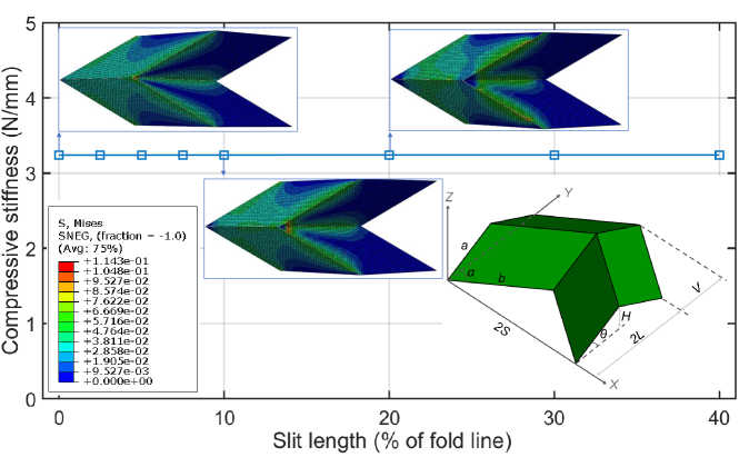
In previous work on a rigid-foldable Miura-ori tube, the size of the vertex cut-out had not been found to impact its mechanical response [Grey et al., 2019]. This observation is here demonstrated for a single planar Miura-ori unit cell.
The unit cell geometry is shown inset in Figure 6. Dimensions and are crease lengths, is facet angle, is the angle between the facets and the horizontal base; the remaining geometric parameters can be calculated [Schenk and Guest, 2013]. The material parameters are the same as those used in the main letter. The nodes in the -plane are constrained in the -direction, while a compressive displacement of is applied on the other end of the unit cell. All other degrees of freedom on both two ends are left unconstrained. The slit length changes from 0 to 40% of the fold line, and the total fold stiffness along each fold line maintains the same.
Figure 6 shows that the compressive stiffness of the unit cell remains nominally constant for increasing slit length at the vertex. This illustrates that for a rigid-foldable pattern, in contrast with the origami bellows, the effect of the slit length can in effect be neglected.
Appendix C Sensitivity of Bellows Axial Stiffness
In the main text, the compressive stiffness of the origami bellows is shown to be highly sensitive to the slit length; here we show that this phenomenon is not limited to the particular combination of fold stiffness and material thickness used in the main letter. And we also demonstrate the minimal sensitivity to fold stiffness and mesh density.
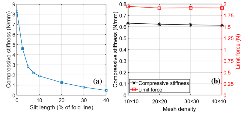
First, we increase the fold stiffness per unit length of fold to 0.5 N/rad and vary the slit length from 0 to 40%. The other parameters remain unchanged. The significant decrease in axial compressive stiffness with respect to slit length is again observed; see Fig. 7(a). Next, for the Miura-ori bellow with slit length = 2.5% of the fold line, we increase the fold stiffness per unit length of fold by 5%, 10% and 15%, namely , , , N/rad. The compressive stiffness increases 0.67%, 1.23% and 1.97% correspondingly, see Table 1, which shows that the influence of on the compressive behaviour is not distinct. Lastly, a mesh sensitivity study was conducted, increasing the mesh density from to elements per facet whilst keeping the slit length equal to 10% of the fold line length. Both Fig. 7(b) and Table 2 show that if the mesh density is finer than , the compressive stiffness as well as limit force are almost the same (maximum difference is within 3%) under different mesh sizes. However, in order to simulate fine slits such as slit length = 2.5% of the fold line, mesh density is chosen as elements per facet.
| (N/rad) | Increase (%) | (N/mm) | Increase (%) |
|---|---|---|---|
| 0.05 | - | 2.841 | - |
| 0.0525 | 5% | 2.860 | 0.67% |
| 0.055 | 10% | 2.879 | 1.23% |
| 0.0575 | 15% | 2.897 | 1.97% |
| Mesh density | (N/mm) | Change (%) | (N) | Change (%) |
|---|---|---|---|---|
| 0.632 | - | 1.948 | - | |
| 0.622 | -1.58% | 1.910 | -1.95% | |
| 0.617 | -2.37% | 1.913 | -1.80% | |
| 0.614 | -2.85% | 1.911 | -1.90% |
Appendix D Refined FE Model for Miura-ori
In experiments of Miura-ori bellows with slit length = 0% and 5% of fold line, debonding between plates and the ends of bellows is observed. This phenomenon is caused by the unique reaction force distribution at the bottom of the Miura-ori bellows; see Fig. 4(b). A positive reaction force is observed at the vertices at valley folds while reaction force at the vertices at mountain folds is negative (i.e. pulling upwards from base, despite global compression load on bellows). Our study also shows that this phenomenon is robust to different compressive displacements and slit lengths. Therefore, vertices at mountain folds have the trend to pull away from the plates.
In order to capture the debonding effect, the numerical model was refined to reflect the experimental configuration in more detail; see Fig. 8. At the vertices near the end plates, 40% of the edges of the end tabs and 10% of the fold lines are left unconstrained to facilitate the lifting up phenomenon; see Fig. 8. For the remaining edges of the end tabs, the translational motion on the z-axis is constrained; all translational degrees of freedom are constrained at the holes. A compressive displacement of 30% of the initial height of the bellow is applied along the bellows’ cylindrical z-axis at the edges of the end tabs and holes on the top.
Appendix E Experimental Validation Miura-ori
This section presents further experimental validations of simulation results for Miura-ori bellows (results for Kresling are presented in the main text). Fig. 9(a)-(c) depict the experimental and numerical force-displacement responses of Miura-ori bellows with different slit lengths. For bellow with slit length = 5%, 10% and 20%, the experimental results match well with the simulations, and the relative error for initial compressive stiffness is within 20%. The compression of the Miura-ori bellow with slit length= 10% is shown in Fig. 9(c) and the deformed configurations show good qualitative consistency.
| Slit length (%of fold line) | FE | Experiment | Relative error (%) |
|---|---|---|---|
| 0 | 20.14 | 16.32 | 18.97% |
| 5 | 7.01 | 8.31 | 18.54% |
| 10 | 2.48 | 2.96 | 19.35% |
| 20 | 0.97 | 0.78 | 19.59% |
| Slit length (%of fold line) | FE | Experiment | Relative error(%) |
|---|---|---|---|
| 0 | 108.07 | 47.59 | 55.96% |
| 5 | 12.08 | 11.49 | 4.88% |
| 10 | 9.16 | 7.49 | 18.23% |
| 20 | 2.87 | 2.79 | 2.79% |
Appendix F Smooth Fold Lines
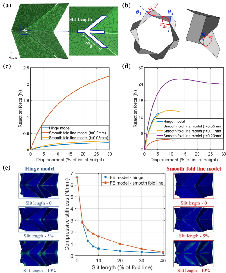
The modelling idealisation of a zero-width fold line with linear torsion spring was refined by introducing a smooth fold line: a cylindrical section joins the adjacent facets. A unit cell with a smooth fold line is shown in Fig. 10(a), where the radius of crease is 0.85 mm. The width of the smooth crease is dependent on the radius (see Figure 10(b)) , which can be calculated as:
| (8) |
In origami structures, the bending stiffness at the creases is lower than that of the facets to facilitate localised folding. This could be modelled by decreasing the material modulus at the crease [Woo et al., 2008]. Here, we achieve this by locally reducing the material thickness along the crease. One unit cell in the bellow (geometric and material parameters are the same as that in the main letter) without slits is taken to calibrate the thickness of creases to match the result of the hinge model; note that this single unit cell is rigid-foldable as the objective is to match the fold stiffness. The boundary condition is the same as that applied in Appendix B. It is found out that the thickness of creases should be reduced from 0.2 mm to 0.05 mm to match the result (Figure 10(c)). However, for one layer of a Miura-ori bellow without slits, applying crease thickness mm will underestimate the stiffness of the whole model. The discrepancy between the thickness can be explained by the introduction of crease shearing in the one layer model while the unit cell model can be regarded as rigid-foldable. Therefore, the thickness is adjusted to 0.11 mm (Figure 10(d)), and this value is used in the simulation.
As shown in Figure 10(e), the rapid reduction of compressive stiffness as a result of increasing slit length is observed in both the hinge model and smooth fold line model. This indicates that the influence of slit length is robust to different crease modelling methods.