22email: stefan.ploner@fau.de
A Spatiotemporal Model for Precise and Efficient Fully-automatic 3D Motion Correction in OCT
Abstract
Optical coherence tomography (OCT) is a micrometer-scale, volumetric imaging modality that has become a clinical standard in ophthalmology. OCT instruments image by raster-scanning a focused light spot across the retina, acquiring sequential cross-sectional images to generate volumetric data. Patient eye motion during the acquisition poses unique challenges: Non-rigid, discontinuous distortions can occur, leading to gaps in data and distorted topographic measurements. We present a new distortion model and a corresponding fully-automatic, reference-free optimization strategy for computational motion correction in orthogonally raster-scanned, retinal OCT volumes. Using a novel, domain-specific spatiotemporal parametrization of forward-warping displacements, eye motion can be corrected continuously for the first time. Parameter estimation with temporal regularization improves robustness and accuracy over previous spatial approaches. We correct each A-scan individually in 3D in a single mapping, including repeated acquisitions used in OCT angiography protocols. Specialized 3D forward image warping reduces median runtime to < 9 s, fast enough for clinical use. We present a quantitative evaluation on 18 subjects with ocular pathology and demonstrate accurate correction during microsaccades. Transverse correction is limited only by ocular tremor, whereas submicron repeatability is achieved axially (0.51 µm median of medians), representing a dramatic improvement over previous work. This allows assessing longitudinal changes in focal retinal pathologies as a marker of disease progression or treatment response, and promises to enable multiple new capabilities such as supersampled/super-resolution volume reconstruction and analysis of pathological eye motion occuring in neurological diseases.
Keywords:
Optical coherence tomography Motion compensation Non-rigid registration Forward warping.1 Introduction
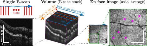
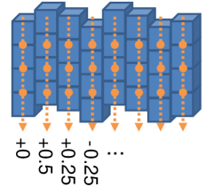
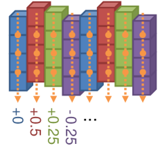
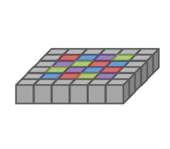
Imaging the eye is particularly challenging because three types of involuntary eye movements continuously occur even during fixation [16]: Microsaccades (occasional fast movements lasting < 25 ms), drift (slow, random walk-like motion causing distortion throughout), and tremor (aperiodic transverse vibration below the resolution of non-adaptive optics retinal imaging). Fixation capabilities decrease with age and in pathology. Optical coherence tomography (OCT) is a non-invasive 3D imaging modality and standard of care in ophthalmology [10]. By raster-scanning a laser beam across the retina, OCT assembles a volume of quasi-instantaneous depth profiles of backscattering (A-scans). A line of A-scans forms a 2D cross-sectional image (B-scan) with minimal distortion due to a millisecond acquisition (Figure 1). In contrast, volume acquisition requires seconds and is correspondingly more distorted in slow scan direction. Microsaccades appear as discontinuities and cause gaps if performed opposite to the slow scan direction. OCT angiography (OCTA) visualizes microvasculature by performing repeated B-scans at the same retinal location and detecting motion contrast from moving blood cells [20]. However, scan time and distortion are further increased.
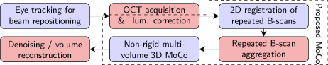
Previous motion correction methods are based on a three-step procedure outlined in Figure 2. Eye tracking compensates motion and, thus, gap size during acquisition, but is insufficient as typically only transverse motion is corrected, and accuracy is fundamentally limited by latency in the range of a microsaccade duration [19]. Secondly, repeated B-scans are affinely registered. This step is limited to correcting in-plane (2D) motion by its 2D nature [20]. Subsequently, repeated B-scans are aggregated by averaging (OCT) or variance computation (OCTA). Lastly, two or more volumes are coregistered, allowing latency-free 3D distortion correction. Additional scans increase acquisition time, but enable data fusion for gap filling and signal-to-noise ratio enhancement [20].
For the volumetric correction, typically a pair of volumes with orthogonally oriented B-scans is used. This allows correcting distortion along the slow scan direction with the B-scans of the orthogonal volume and vice-versa. The main challenges are lack of a distortion-free reference, and the spatial discontinuity in distortion due to raster-scanning. Brea et al. reviewed existing methods and concluded that current models are insufficient to accurately correct fine features [21]. More recently, Ploner et al. integrated utilization of OCTA data [17] into the method of Kraus et al. [11], which is in commercial use. A special feature of these methods is that they are reference-free: displacement fields for each scan are jointly estimated in an axial, followed by a 3D, iterative optimization. This avoids propagation of drift motion from a reference to the result. Axial undistortion is achieved reliably, but correction is limited by use of backward warping: B-scan shearing must be estimated and compensated in the initial axial optimization, but this introduces inaccuracies because it lacks correction of transverse motion. Discontinuities in the distorted inputs (pink markers in Figure 1) may cause spurious gradients in the similarity metric (during optimization). Furthermore, backward-warped displacements are defined at target grid voxels, limiting continuity regularization to target grid axes. However, B-scans acquired during slow scan direction motion or torsional eye motion (around the optical axis) are no longer axis-aligned with the target grid. This must be compensated by discontinuities in the displacement fields which violate the regularizer. Consequently, issues occur in datasets with head tilt (many volumes or widefield), and misregistration persists especially near slow scan direction microsaccades. While, e. g., the method of Athwal et al. compensates torsional motion [2], its local undistortion is limited (see discussion). The more promising forward warping was avoided for iterative OCT motion correction because the necessary scattered data interpolation was assumed computationally infeasible for clinical settings.
Contribution. We present the first spatiotemporal motion model and a corresponding fully-automatic, reference-free optimization strategy for volumetric distortion correction in OCT. Our approach introduces numerous advances over the state of the art: By using a displacement field parametrization with respect to time, discontinuities in optimization are remedied. Compared to prior work, a drastically reduced parameter density suffices without compromising accuracy, and smoothness regularization no longer contradicts with discontinuities. Two features are critical to enable time-continuous modeling: First, in order to infer consistent displacements despite distinct A-scan locations, motion is described for the eye as a whole, by a spatially rigid 3D transform. Remaining change is assumed to be of temporal origin. Secondly, to be able to derive the displacement of each A-scan based on its acquisition time, the transform must be defined at the input voxels, i. e. formulated via forward warping. While forward warping (FW) is fundamentally more complex to compute than backward warping, it enables image warping using a single, direct mapping. This allows estimation of all parameters in a single optimization, towards the (iteratively) fully corrected orthogonal dataset. A further advantage of FW is its correct handling of overlaps, which enables individual registration of repeated B-scans during volume registration. This not only removes the necessity for prior registration and intermediate averaging of B-scan repeats, but more importantly, enables their correction in all three spatial dimensions. Besides improving accuracy, this can substantially reduce gap size compared to prior in-plane registration methods. Finally, FW enables direct integration of head tilt compensation, effective compensation of displacement bias from resampling effects, and gradient computation in the iteratively motion-corrected targets, thereby bypassing spurious gradients in the input volumes. Our model is suited for volume-pair, many-volume and widefield imaging, and is more reliable, dramatically more accurate, and converges faster. As discussed at the end, a range of new applications is enabled. Lastly, by exploiting the structure of possible distortion in the model, we formulate a domain-specific, separable forward interpolation scheme to enable iterative optimization in clinically feasible runtimes. While adding all described advantages, previously reported runtimes are reduced by a factor of 5.
2 Methods
Our approach jointly motion corrects two or more volumes with orthogonal B-scans. The log-scale B-scans are preprocessed with a radius 1 px median filter and factor 2 axial downsampling. OCT volumes are displayed in a grid where x, y displacements are within the coronal plane and z corresponds to depth. We assume the image to be distorted by the 3D affine, temporally varying transform
| (1) |
Here, and are the 3D position and acquisition time of a voxel and is the vector of motion parameters for all scans. is the transverse (x,y) and axial (z) displacement of the retina. Depending on the fast scan direction, either or is nonzero and describes axial shearing of B-scans originating from scanning beam to pupil center alignment [11]. The transverse rotation corresponds to torsional motion [13], which we assume constant within each scan. For all other parameter types, parameters (e. g. ) are estimated for the time points corresponding to the centers of each B-scan repeat and then interpolated along time using a cubic hermite spline () to attain A-scan-specific values. To reduce displacement bias from equidistant resampling of the registration target grid to the axes-aligned moving B-scans [1], a constant is added. Lastly, besides other effects, illumination can vary with beam alignment / motion, and potentially confound registration. Therefore, based on a (log-scale) voxel intensity , change in illumination is modeled as
| (2) |
where is a spline given by parameters , is the indicator function, and is a threshold to ignore the background, which is not affected by illumination.
Parameters are optimized jointly by minimization of the objective function
| (3) |
comprised of data terms for all volumes , and a smoothness regularization term , which penalizes the squared difference between sequential parameters with parameter type-specific weighting factors. Optimization is performed via momentum gradient descent with parameter type-specific step sizes until the maximum change falls below a threshold. The constraint enforces parameters to have zero mean (by mean subtraction after each optimizer step). Optimization is performed in a 4-level coarse-to-fine multi-resolution pyramid of the (preprocessed) input, created by consecutive factor 2 downsamplings in axial direction. Axial displacement parameters are initialized to the average depth of the voxels of temporally neighboring A-scans, weighted by their cubed intensity. This aligns the bright horizontal band corresponding to the retinal pigment epithelium (see B-scan in Figure 1). Other parameters are initialized with zeros.
Each data term operates on the illumination-corrected voxels of a moving volume , where , , and are a voxel’s A-scan index, depth index, intensity and acquisition time. To compute the corresponding squared difference loss for each target , target volumes are interpolated to the voxel’s motion-corrected location , where is the original voxel position, via 3D cubic hermite spline interpolation :
| (4) |
Only volumes with orthogonal B-scan orientation (given by ) are used as targets. and are the number of A-scans and their depth. Target volumes are assumed constant within each data term evaluation, to limit computational demands of the gradient evaluation. The implementation for forward-warping the targets’ A-scans by is detailed later. Due to use of forward warping, gaps in are known. Consequently, is only defined if the neighborhood around the moving voxel’s location is valid, and ignored otherwise, as determined by . In the final multi-resolution level, the target volume is computed with similar resolution as the preprocessed input, and is reduced in factor 2 steps in all dimensions for the smaller levels. Again, to avoid displacement bias during resampling [1], pseudo-random subpixel offsets are introduced by a slightly lower transverse resolution and z-position offsets (detailed in supplementary Figure 6).
Besides accuracy, a primary concern for algorithm design was a small memory footprint, to allow joint registration of many volumes on a single GPU. Under these preconditions, the algorithm was designed for massively parallel computing throughout and implemented in CUDA 11.1. The most demanding step is the forward-resampling of the target volume. Naive mapping to a neighborhood in the target grid necessitates complex computations to determine each voxel-specific weight, rendering the method infeasible for clinical use. We utilize the absence of axial distortion within A-scans in two critical ways: First, we perform a cubic hermite spline-weighted warping only in axial direction of each A-scan, such that data points are axially aligned with the target grid voxels. This limits the complexity of scattered-data warping to the 2 transverse dimensions only, where we use a truncated Gaussian weighting (sidelength 4, , in target pixels). Secondly, we precompute and share coefficients across the axial direction. For a volume with sidelength , separability and precomputation dramatically reduce the number of coefficient computations from to .
3 Experiments and Results
A dataset of 18 patients was acquired on a prototype spectral domain OCT scanner with 128 kHz A-scan rate over a mm field with A-scans without B-scan repeats. The axial resolution was 3 µm FWHM, axial pixel spacing was 1.78 µm, A-scans had 775 pixels. For each subject, in one eye, 4 volumes were acquired at the fovea with alternating B-scan orientation. Eye tracking was not available. The study cohort is detailed in the supplementary material, Table 2. We used 6 subjects to tune hyperparameters, mainly step size and convergence tolerance, and report our results on the remaining 12 subjects.
Evaluation of OCT motion correction accuracy is challenging [21], ground truth motion is not available. Discontinuities limit the definition of landmarks, as well as error computation between backward displacements, to pixel accuracy. Positional ambiguities arise due to overlaps/gaps. This doesn’t apply to the axial direction, which was evaluated in [11] via reproducibility of segmented retinal layers, but localization accuracy (3 µm [9]) is worse than registration accuracy. In contrast, forward-warped displacements allow direct computation of exact differences. We register each scan to both orthogonally acquired scans independently. Local distortion is independent from the coregistered scan used, so both estimated displacement fields should be identical up to global differences from scanner-to-eye alignment, which must be compensated. We used two transforms: Eq. (1), fixed to a single time-point , only removes rigid movement in the optical setup, and describes (all) residual distortion. The affine-like transform removes two further types of global linear distortion, leaving only local distortion and providing a descriptor of misalignment. This transform, and prevention of bias from resampling effects, are described in the supplementary material.
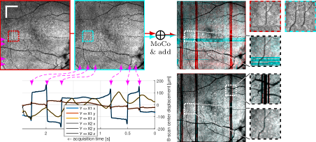
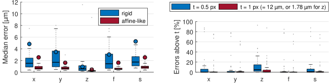
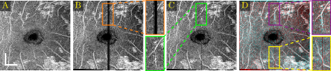
Images and estimated displacements are shown for a representative scan in Figure 3. Tiny discontinuities prove absence of overregularization, and consistent transverse vibration indicates partial correction of ocular tremor. For quantitative analysis, we computed the median distance between the aligned A-scan displacements, and the fraction of displacements with a distance above 0.5 (problematic for supersampling) and 1 pixels (misalignments). The first and last 5% of B-scans were excluded, because they might not overlap with the orthogonal data, preventing registration. As the distributions are heavily skewed, we present box plots in Figure 4. The three outliers in each direction in the right plot originate from the same subject, which is shown in supplementary Figure 6. It is critical to note that the parameter density (B-scan rate 205 Hz) of the hermite splines is insufficient to fully correct ocular tremor (frequency up to 100 Hz [16]). Therefore, this aperiodic, wave-like motion (amplitude 30′′ 1.6 µm on the retina [16]) cannot be fully corrected, and neither is fully represented in the reproducibility error. In the transverse directions, this puts a lower accuracy limit on the evaluation scheme, but it is small compared to the pixel spacing (12 µm). Using an Nvidia RTX 5000 GPU, the median and maximum runtime in the test set, excluding disk I/O which is irrelevant in clinical routine, was 8.6 s and 31.3 s. Table 1 compares average runtimes of various methods. Lastly, registration of individual B-scan repeats is demonstrated on a swept-source scanner in Figure 5.
4 Discussion
Using our spatiotemporal model, we achieve robust estimation of 3D motion traces of the retina in pathology even during fast microsaccadic eye movements. Registration accuracy is improved dramatically, to sub-micron residual axial distortion (0.51 µm median of medians) and even smaller local distortion (misalignment) of 0.20 µm median of medians. Transverse errors are only limited by ocular tremor (peak-to-peak amplitude less than µm px). At the same time, on single- or merged-B-scan-repeat data, the runtime of our approach outperforms published methods by a factor of 5 and more. Whereas runtime increases with additional B-scan repeats, the necessity for prior registration of repeated B-scans is removed. We presented the first metric/distance-based 3D error quantification in OCT motion correction. Due to lack of such evaluation of previous methods, a direct comparison is not possible (see section 3). However, by investigating algorithm properties, lower bounds for accuracy can be derived: Athwal et al. create a registration target by stitching saccade-free segments [2]. Drift motion in the reference segment is not corrected, resulting in residual transverse distortion in the range of 6′ 19.1 µm on the retina [16] and alignment is computed in whole-pixel steps only (12 µm in our dataset, typically µm). Axial registration is limited by segmentation accuracy (ca. 3 µm [9]) and reliability is limited in pathology [2]. In [11] and [17], performing the B-scan shear estimation before transverse motion compensation puts a limit on overall axial registration accuracy. 7.0 and 3.7 µm were reported for axial reproducibility and misalignment errors. However, the evaluation compared retinal layer positions, whose segmentation introduces additional error. As detailed in the introduction, these methods are further limited by model inaccuracies in the transverse directions, and are unreliable near microsaccades [17]. Incompatibility with head rotation limits applicability to many-volume and widefield registration [13]. Displacement bias from resampling was not discussed in prior 3D OCT registration literature.
The advances of our model open up various new possibilities for exploration that go beyond motion correction: Subpixel-accuracy and direct forward warping allow supersampling using repeated volume scans [8], enabling a new paradigm for high-density widefield OCT imaging that is more robust to saccadic eye motion. OCT-derived blood flow signals like OCTA [20] can not only be merged and analyzed at capillary vasculature scale, but the maintained temporal dependency allows cardiac cycle-aware 4D spatiotemporal analysis and reconstruction of flow speeds via Doppler-OCT [12] and VISTA-OCTA [18]. For both OCT intensity and derived signals, advanced 3D signal reconstruction allows probabilistic maximum a-posteriori modeling of the non-Gaussian noise distribution [4] in the reconstruction loss, or deblurring [5], directly based on raw voxel data. The reconstructed eye motion trace extends OCT with potential for accessible screening of neurological diseases that manifest in oculomotor dysfunction [6, 7, 15].
Given the variety of ocular pathologies and OCT scanners, performance should be reaffirmed in a larger cohort. Hardware tracking could be included to improve reliability and prevent longer runtimes in subjects with severe motion. To make optimal use of the motion correction, we are working on an iterative reconstruction and plan a release of the complete framework in the future.
4.0.1 Acknowledgements.
DFG MA 4898/12-1, NIH 5-R01-EY011289-35.
References
- [1] Aganj, I., Yeo, B.T.T., Sabuncu, M.R., Fischl, B.: On removing interpolation and resampling artifacts in rigid image registration. IEEE Transactions on Image Processing 22(2), 816–827 (2013). https://doi.org/10.1109/TIP.2012.2224356
- [2] Athwal, A., Balaratnasingam, C., Yu, D.Y., Heisler, M., Sarunic, M., Ju, M.: Optimizing 3D retinal vasculature imaging in diabetic retinopathy using registration and averaging of OCT-A. Biomed. Opt. Express 12(1), 553–570 (2021). https://doi.org/10.1364/BOE.408590
- [3] Cheng, Y., Chu, Z., Wang, R.K.: Robust three-dimensional registration on optical coherence tomography angiography for speckle reduction and visualization. Quantitative Imaging in Medicine and Surgery 11(3) (2021). https://doi.org/10.21037/qims-20-751
- [4] Dubose, T.B., Cunefare, D., Cole, E., Milanfar, P., Izatt, J.A., Farsiu, S.: Statistical models of signal and noise and fundamental limits of segmentation accuracy in retinal optical coherence tomography. IEEE Transactions on Medical Imaging 37(9), 1978–1988 (2018). https://doi.org/10.1109/TMI.2017.2772963
- [5] Farsiu, S., Robinson, M., Elad, M., Milanfar, P.: Fast and robust multiframe super resolution. IEEE Transactions on Image Processing 13(10), 1327–1344 (2004). https://doi.org/10.1109/TIP.2004.834669
- [6] Fletcher, W.A., Sharpe, J.A.: Saccadic eye movement dysfunction in alzheimer’s disease. Annals of Neurology 20(4), 464–471 (1986). https://doi.org/10.1002/ana.410200405
- [7] Gitchel, G.T., Wetzel, P.A., Baron, M.S.: Pervasive Ocular Tremor in Patients With Parkinson Disease. Archives of Neurology 69(8), 1011–1017 (2012). https://doi.org/10.1001/archneurol.2012.70
- [8] Greenspan, H.: Super-Resolution in Medical Imaging. The Computer Journal 52(1), 43–63 (2008). https://doi.org/10.1093/comjnl/bxm075
- [9] He, Y., Carass, A., Liu, Y., Jedynak, B.M., Solomon, S.D., Saidha, S., Calabresi, P.A., Prince, J.L.: Fully convolutional boundary regression for retina oct segmentation. In: Shen, D., Liu, T., Peters, T.M., Staib, L.H., Essert, C., Zhou, S., Yap, P.T., Khan, A. (eds.) Medical Image Computing and Computer Assisted Intervention – MICCAI 2019. pp. 120–128. Springer International Publishing (2019). https://doi.org/10.1007/978-3-030-32239-7_14
- [10] Huang, D., Swanson, E., Lin, C., Schuman, J., Stinson, W., Chang, W., Hee, M., Flotte, T., Gregory, K., Puliafito, C., Fujimoto, J.: Optical coherence tomography. Science 254(5035), 1178–1181 (1991). https://doi.org/10.1126/science.1957169
- [11] Kraus, M., Liu, J.J., Schottenhamml, J., Chen, C.L., Budai, A., Branchini, L., Ko, T., Ishikawa, H., Wollstein, G., Schuman, J., Duker, J., Fujimoto, J., Hornegger, J.: Quantitative 3D-OCT motion correction with tilt and illumination correction, robust similarity measure and regularization. Biomed. Opt. Express 5(8), 2591–2613 (2014). https://doi.org/10.1364/BOE.5.002591
- [12] Leitgeb, R.A., Werkmeister, R.M., Blatter, C., Schmetterer, L.: Doppler optical coherence tomography. Progress in Retinal and Eye Research 41, 26–43 (2014). https://doi.org/10.1016/j.preteyeres.2014.03.004
- [13] Lezama, J., Mukherjee, D., McNabb, R., Sapiro, G., Kuo, A., Farsiu, S.: Segmentation guided registration of wide field-of-view retinal optical coherence tomography volumes. Biomed. Opt. Express 7(12), 4827–4846 (2016). https://doi.org/10.1364/BOE.7.004827
- [14] Makita, S., Miura, M., Azuma, S., Mino, T., Yamaguchi, T., Yasuno, Y.: Accurately motion-corrected lissajous OCT with multi-type image registration. Biomed. Opt. Express 12(1), 637–653 (2021). https://doi.org/10.1364/BOE.409004
- [15] Mallery, R.M., Poolman, P., Thurtell, M.J., Full, J.M., Ledolter, J., Kimbrough, D., Frohman, E.M., Frohman, T.C., Kardon, R.H.: Visual Fixation Instability in Multiple Sclerosis Measured Using SLO-OCT. Investigative Ophthalmology & Visual Science 59(1), 196–201 (2018). https://doi.org/10.1167/iovs.17-22391
- [16] Martinez-Conde, S., Macknik, S., Hubel, D.: The role of fixational eye movements in visual perception. Nat Rev Neurosci 5(3), 229–240 (2004). https://doi.org/10.1038/nrn1348
- [17] Ploner, S.B., Kraus, M., Moult, E., Husvogt, L., Schottenhamml, J., Alibhai, A., Waheed, N., Duker, J., Fujimoto, J., Maier, A.K.: Efficient and high accuracy 3-D OCT angiography motion correction in pathology. Biomed. Opt. Express 12(1), 125–146 (2021). https://doi.org/10.1364/BOE.411117
- [18] Ploner, S.B., Moult, E.M., Choi, W., Waheed, N.K., Lee, B., Novais, E.A., Cole, E.D., Potsaid, B., Husvogt, L., Schottenhamml, J., Maier, A., Rosenfeld, P.J., Duker, J.S., Hornegger, J., Fujimoto, J.G.: Toward quantitative optical coherence tomography angiography. Retina 36, S118–S126 (2016). https://doi.org/10.1097/IAE.0000000000001328
- [19] Schwarzhans, F., Desissaire, S., Steiner, S., Pircher, M., Hitzenberger, C.K., Resch, H., Vass, C., Fischer, G.: Generating large field of view en-face projection images from intra-acquisition motion compensated volumetric OCT data. Biomed. Opt. Express 11(12), 6881–6904 (2020). https://doi.org/10.1364/BOE.404738
- [20] Spaide, R., Fujimoto, J., Waheed, N., Sadda, S., Staurenghi, G.: Optical coherence tomography angiography. Progress in Retinal and Eye Research 64, 1–55 (2018). https://doi.org/10.1016/j.preteyeres.2017.11.003
- [21] Sánchez Brea, L., Andrade De Jesus, D., Shirazi, M.F., Pircher, M., van Walsum, T., Klein, S.: Review on retrospective procedures to correct retinal motion artefacts in OCT imaging. Applied Sciences 9(13) (2019). https://doi.org/10.3390/app9132700
- [22] Zang, P., Liu, G., Zhang, M., Wang, J., Hwang, T.S., Wilson, D.J., Huang, D., Li, D., Jia, Y.: Automated three-dimensional registration and volume rebuilding for wide-field angiographic and structural optical coherence tomography. J. Biomed. Opt. 22(2), 26001 (2017). https://doi.org/10.1117/1.JBO.22.2.026001
Supplementary Materials
4.0.2 Global alignment.
| (5) |
Transverse () and diagonal axial sheering () are challenging to correct using orthogonal raster-scans, and constitute most residual distortion. This distortion is consistent among jointly registered scans. When comparing independently corrected scans, e. g. for follow-up, can be used for global alignment, making this distortion clinically irrelevant. After compensation, only local distortions remain. Due to orthogonal acquisition, these must be misalignments.
4.0.3 Potential bias during evaluation.
Registration is susceptible to overly favor solutions where the data is blurred by the interpolator, as can happen when sampling between data points, as this reduces the inconsistency among noisy samples and, consequently, the objective function. Aliasing effects during equidistant resampling of moving, interpolated targets add to this effect [1] (see also supplementary Figure 6). Although we did not observe this in the estimated motion traces, such effects could cause displacements to change not continuously, but “quantized” in pixel-steps. For identical registration targets, such artifactual steps could align consistently and therefore result in small reproducibility errors despite up to half-pixel residual distortion. Using the pseudo-random resampling that prevents these effects between the moving and target volumes in our method, we prohibit these effects also in the reproducibility evaluation, by using different target grid configurations in the two motion-corrections used to generate the compared displacement fields. We used / (), resolution factor / ( 1), and axial offsets (supplementary Figure 6) were offset by / in transverse directions. Potential pixel-steps in the displacements would not be aligned, and, after averaging, result in the expected error.
4.0.4 Unit conversions.
For conversion between rotation angles and distance on retinal surface, we assume a spherical retina with 22 mm diameter.
4.0.5 Author Contributions.
SP is the main author. Algorithm design, evaluation, implementations, initial writing: SP. Scanner design: SC. Data: JW, SC. Result analysis and presentation: SP, KB, SC, JW. Funding: AM, SP, JF. All authors contributed to the final manuscript.
| Set | Pathology | #patients | #eyes | Age | Female |
|---|---|---|---|---|---|
| Train | Age-related macular degeneration | 3 | 3 | 66% | |
| Non-proliferative diabetic retinopathy | 3 | 3 | 33% | ||
| Test | Age-related macular degeneration | 6 | 6 | 50% | |
| Non-/proliferative diabetic retinopathy | 6 | 6 | 50% |