Send correspondence to federico.battaini@inaf.it
The internal alignment and validation of a powered ADC for SOXS
Abstract
The Son Of X-Shooter (SOXS) is a two-channel spectrograph along with imaging capabilities, characterized by a wide spectral coverage (350nm to 2000nm), designed for the NTT telescope at the La Silla Observatory. Its main scientific goal is the spectroscopic follow-up of transients and variable objects. The UV-VIS arm, of the Common Path sub-system, is characterized by the presence of a powered Atmospheric Dispersion Corrector composed (ADC) by two counter-rotating quadruplets, two prisms, and two lenses each. The presence of powered optics in both the optical groups represents an additional challenge in the alignment procedures. We present the characteristics of the ADC, the analysis after receiving the optics from the manufacturer, the emerging issues, the alignment strategies we followed, and the final results of the ADC in dispersion and optical quality.
keywords:
SOXS, ADC, Alignment, AIV1 INTRODUCTION
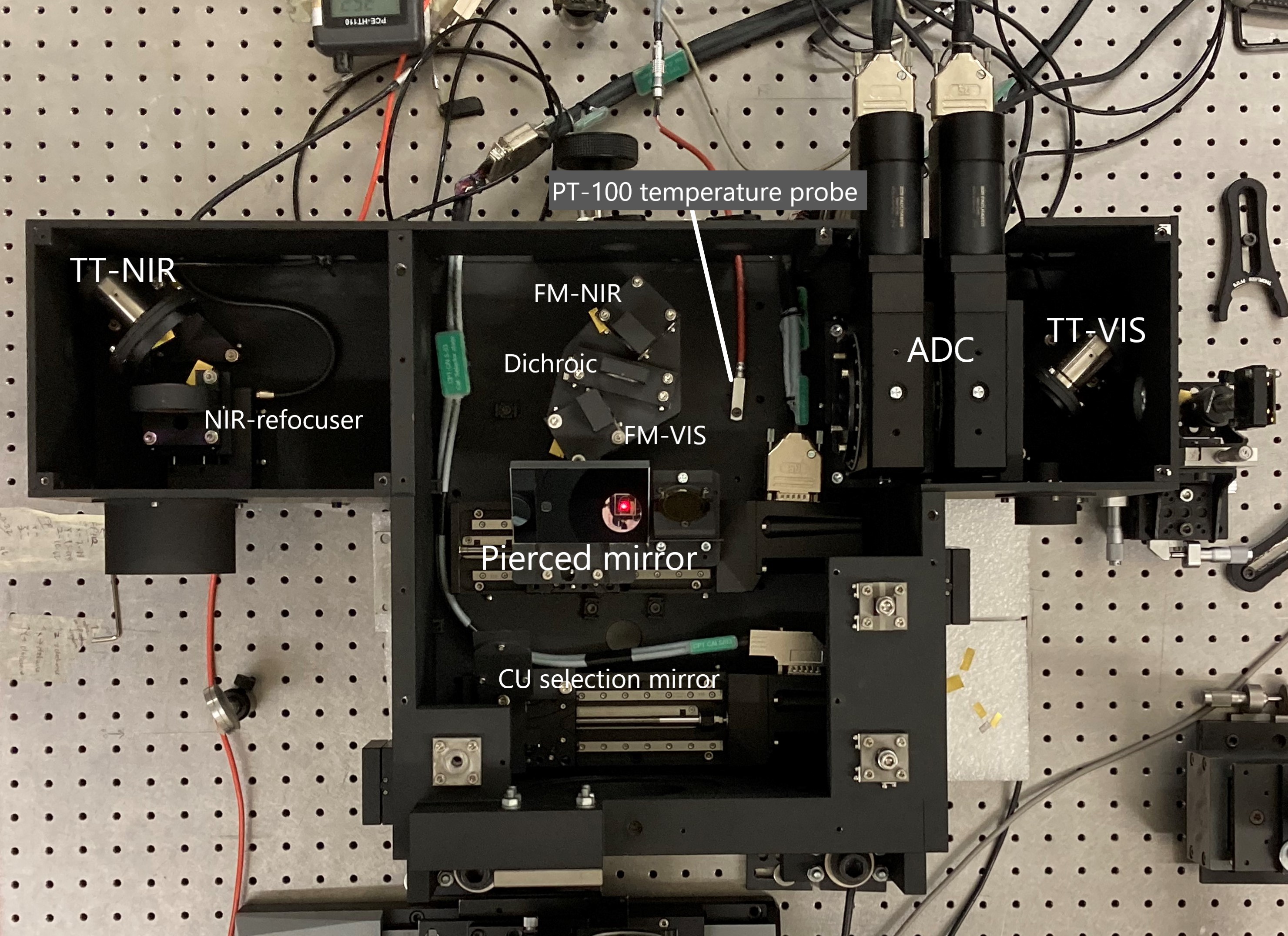
SOXS (Son Of X-Shooter) is a two-channel spectrograph, spanning UV-VIS (350-850nm) and NIR (800-2000nm) wavelength regimes[1]. The Common Path sub-system receives the F/11 telescope beam and splits the UV-VIS and NIR wavelengths and provide F/6.5 beams to the respective spectrographs[2]. In figure 1 is possible to see the Common Path fully populated.
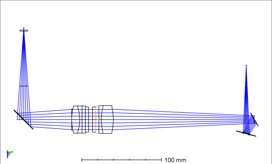
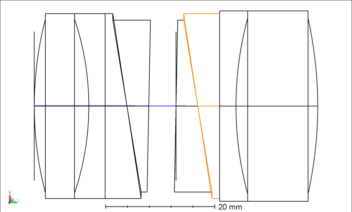
The UV-VIS arm (see Fig. 2) is characterized by the presence of a powered Atmospheric Dispersion Corrector (ADC) that includes both the dispersion elements and optics to reduce the f-number of the beam. The SOXS ADC composed of two counter-rotating quadruplets: each of them has two prisms and two lenses as show in Fig. 3[3]. ArcherOptx manufactured and delivered the two quadruplets inserted in the respective barrels and motors. In the AIV process[4],our analysis suggested re-alignment of the ADC unit to match the required optical performances. The presence of powered optics in both the ADC’s optical groups translates into need for tight tolerances. In order to proceed with the new alignment and to face some possible issues with glue used by the manufacturer we unglued the two quadruplets from their barrels, we performed a temporary alignment and finally we glued it again.
2 ALIGNMENT EVALUATION ON RECEIVING
We performed a series of tests to verify and validate the ADC mounting and alignment. Note that we name the first, in the optical path, quadruplet unit and the motor as ADC1, whose first lens is a CaF2 one, and the other as ADC2.
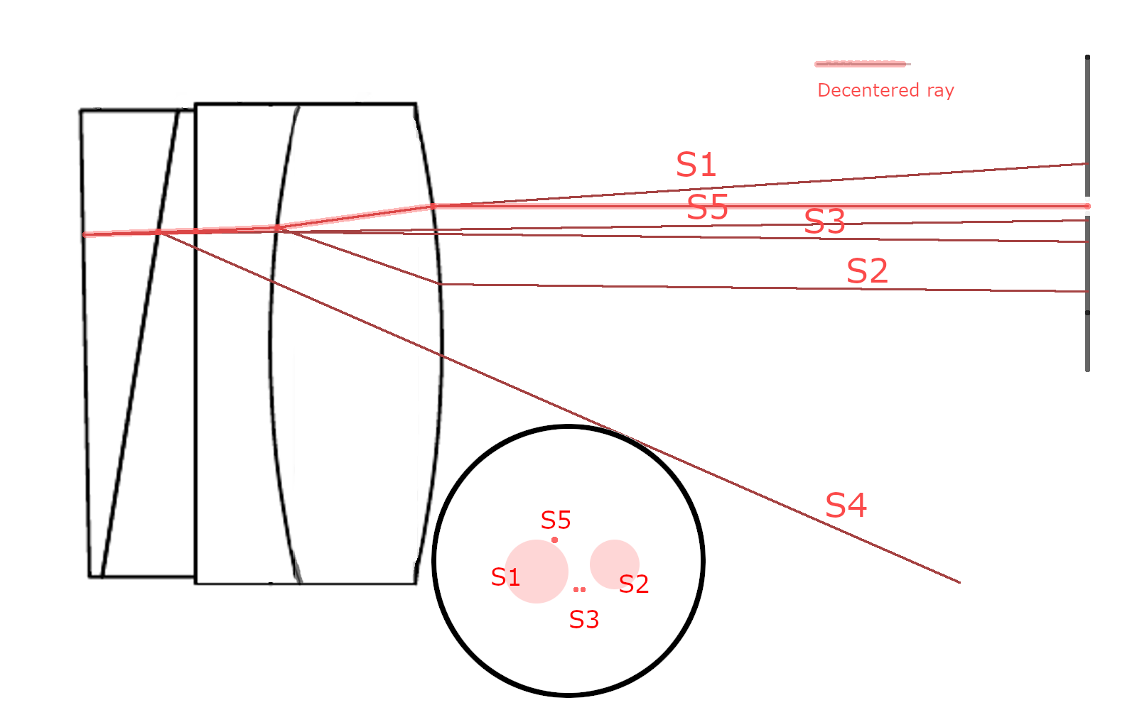
As the first step, we placed the ADC unit on a stage with 5 degrees of freedom X,Y,Z, Z-tilt (in optical axis direction), and rotation. We aligned the ADC unit to the incoming collimated 633nm laser beam using back-reflected ghosts from the ADC1 different surfaces, see fig. 5. We characterized the back reflections by the ray-tracing software and we were able to identify each spot we saw. In this way we used the rotation of these spot while rotating the motor to identify the rotational axis and measuring the tilt of the optics (in particular looking at the angular distance between the S3 reflected beam (Fig. 5) with respect to the rotational axis.
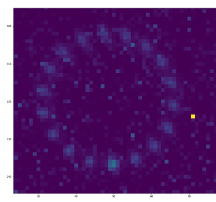
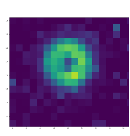
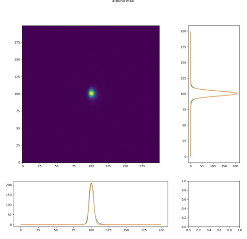
Also, we inspected the spots’ movement at a CCD positioned at the focal plane as the individual motors were rotated. The images stacked in a single frame of the spot with the motors at several different positions are visible in Fig. 4.
-
•
We estimated a misalignment between the optical axis of the ADC1 quadruplet and the rotational axis of the ADC1 motor close to 1.5 degrees.
-
•
We aligned the ADC1 quadruplet optical axis to the incoming beam axis through back reflections. Then we rotated the ADC1 motor 360 deg taking an image at the CCD placed at the focal plane (transmitted through ADC1 and ADC2) every 20deg, keeping ADC2 at fixed position. We see that the spot makes a circle at the CCD with a diameter of 30um (see Fig. 1 left-panel), this value was acceptable.
-
•
In the same optical configuration as the previous point, we rotated the ADC2 motor 360 deg taking an image at the CCD (transmitted through ADC1 and ADC2) every 20deg, keeping ADC1 at fixed position. We see that the spot makes a circle at the CCD with a diameter of 150um (see Fig. 1 right-panel). Unfortunately, this value was too large to be accepted.
-
•
Reversing the ADC position (that is ADC2 facing the incoming beam), we estimated a misalignment between the optical axis of the ADC2 quadruplet and the rotational axis of the ADC2 motor close to 1 degree.
3 METHODS FOR THE NEW ALIGNMENT
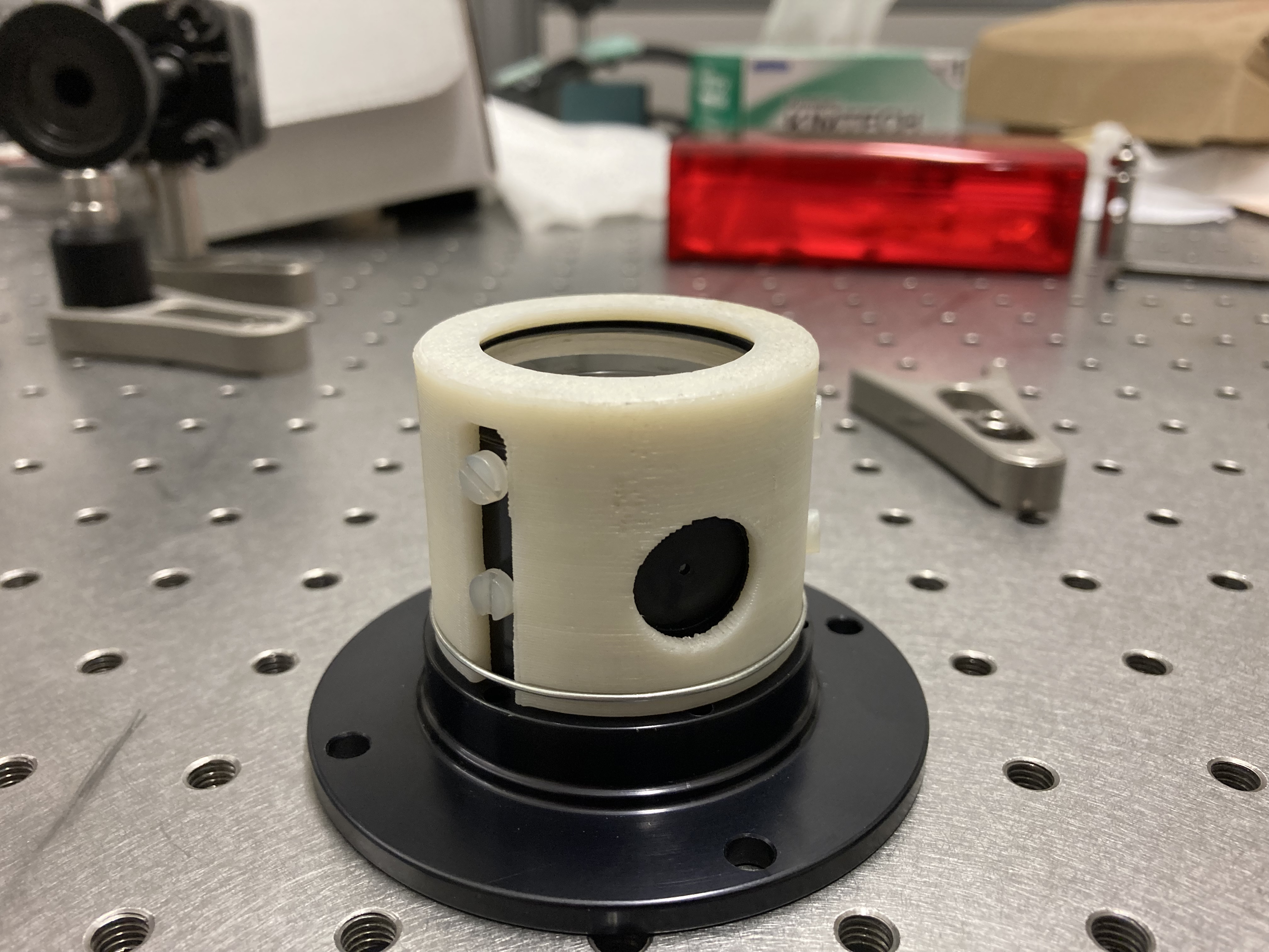
In order to control the tilt of the quadruplet inside the barrel we drilled threaded holes on two rows. The holes can host M3 teflon screws positioned 120° to each other, see Fig. 6.
We also produced two 3D printed holders to prevent any risk of falling off of the quadruplets, see Fig. 6 left panel.
We proceeded with the single unit internal alignment. We used both back reflection from the various surfaces and transmission effect on a 633 nm laser beam and on a telescope simulator beam. We obtained acceptable results at the end of December 2021.
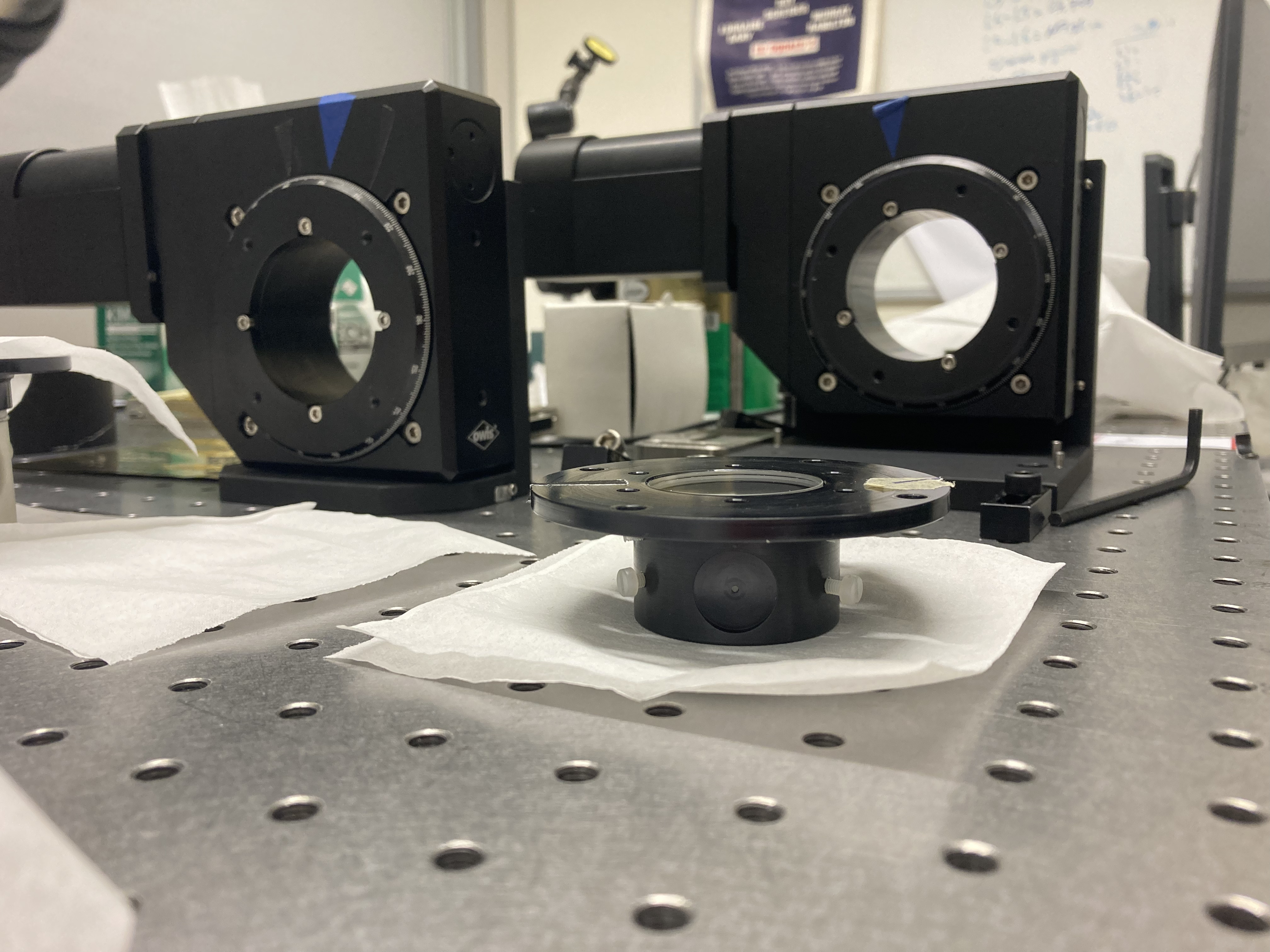
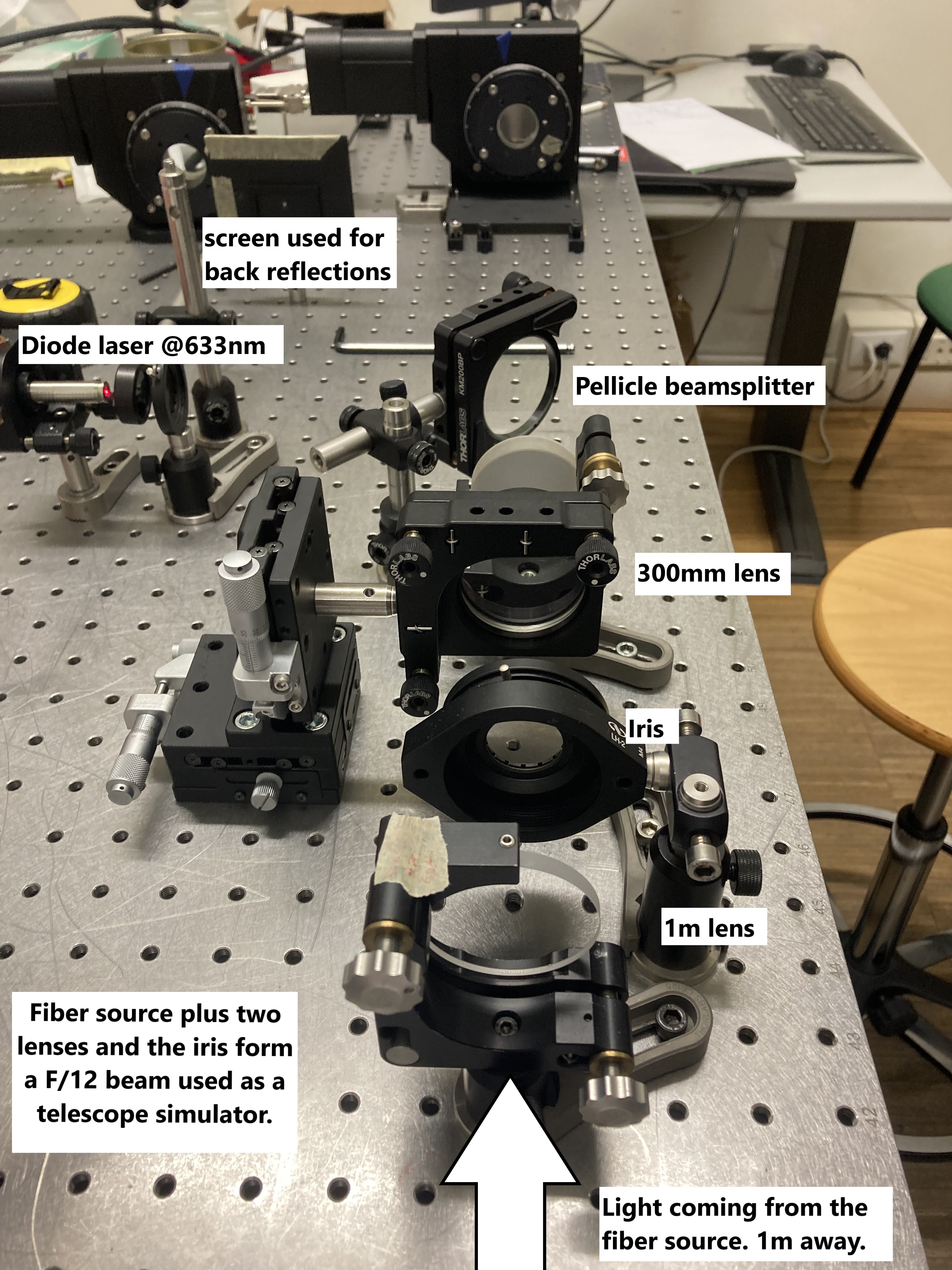
We built a set-up with both a laser reference and an on-axis telescope simulator feed by a Thorlabs SLS201L/M lamp with the possibility to insert narrow band filters. We aligned each subunit wrt the incoming beam using different autocollimation configurations.
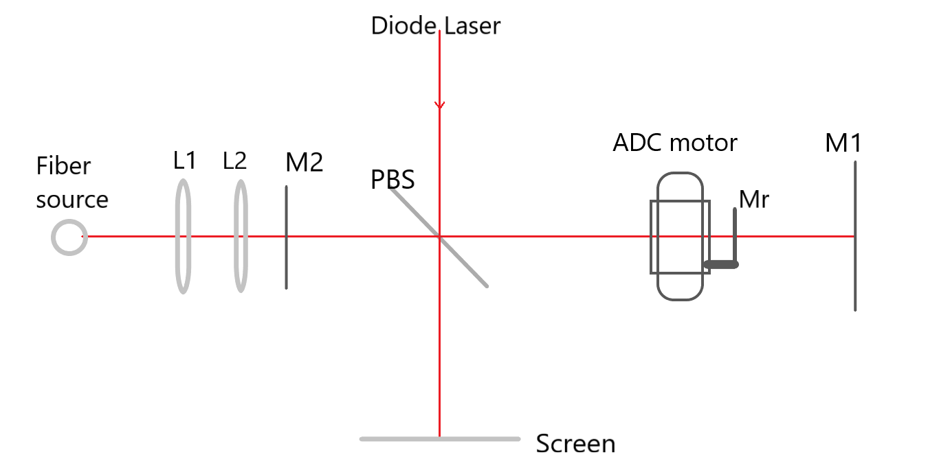
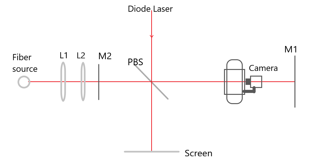
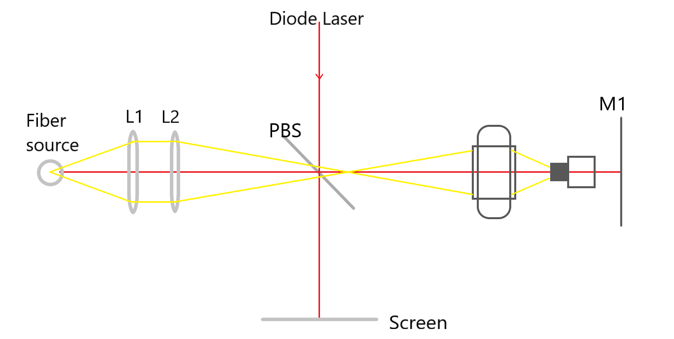
A mirror and then a service camera were used screwed to the rotor to correct tilt and decenter of the motor, see Fig. 8 for a picture of the bench set-up and 7 for a schematic representation of the setup. See figure to
We then aligned the two ADC sub-units (quadruplets) in their modified barrels. In order to assess the alignment and optical performance of the sub-units and the whole ADC we used the following observables:
-
•
Laser back-reflection from the S3 planar surfaces (see Fig. 5) of each quadruplets;
-
•
Movement of the transmitted laser beam while rotating the motors, expected to be close to zero by design at 633nm;
-
•
Dispersion introduced by the quadruplet measured by the diameter of the circle drawn by the on-focus spot using different narrow band filters;
-
•
Psf quality, encircled energy and FWHM.
4 RESULTS AND CONCLUSIONS
We performed a first evaluation of the optical quality in the temporary configuration where the quadruplets were hold in place by the strength of the six teflon screws. The results were good so we proceeded with the re-gluing process. We used an M3 2216 glue that took one week curing time at room temperature.
After a new centering of the barrels in the same way presented in the previous section we integrated the two subunits and and than we moved the ADCinside the Common Path of SOXS. ADC is the only powered optics in the UV-VIS arm inside the CP.
In table 1 we reported the data of alignment obtained for the two sub units.
| Quadruplet tilt | Quadruplet decenter | Tolerances | |
|---|---|---|---|
| ADC 1 | <50” | <20 µm | 180” and 50 µm |
| ADC 2 | <50” | <20 µm | 180” and 50 µm |
We measured the overall optical quality and the dispersion of the ADC. In Table 2 we summarized the data about FWHM and the encircled energy. PSFs have been acquired in white light for a grid of positions centred on on-axis. For each position 10 images have been averaged; to the obtained image, the dark image (obtained averaging the 50 images of dark) has been subtracted. Each obtained PSF has been fitted with a Gaussian. In the following table FWHM along one direction and the perpendicular one is reported as well as the e70,80 and 90 that are the radius containing the 70, 80 and 90% of energy, in microns.
| Zemax simulation[] | Mesured [] | |
|---|---|---|
| FWHM | 21 | 12-16 |
| E70 | 10 | 10-11 |
| E80 | 13 | 11-14 |
| E90 | 17 | 16-21 |
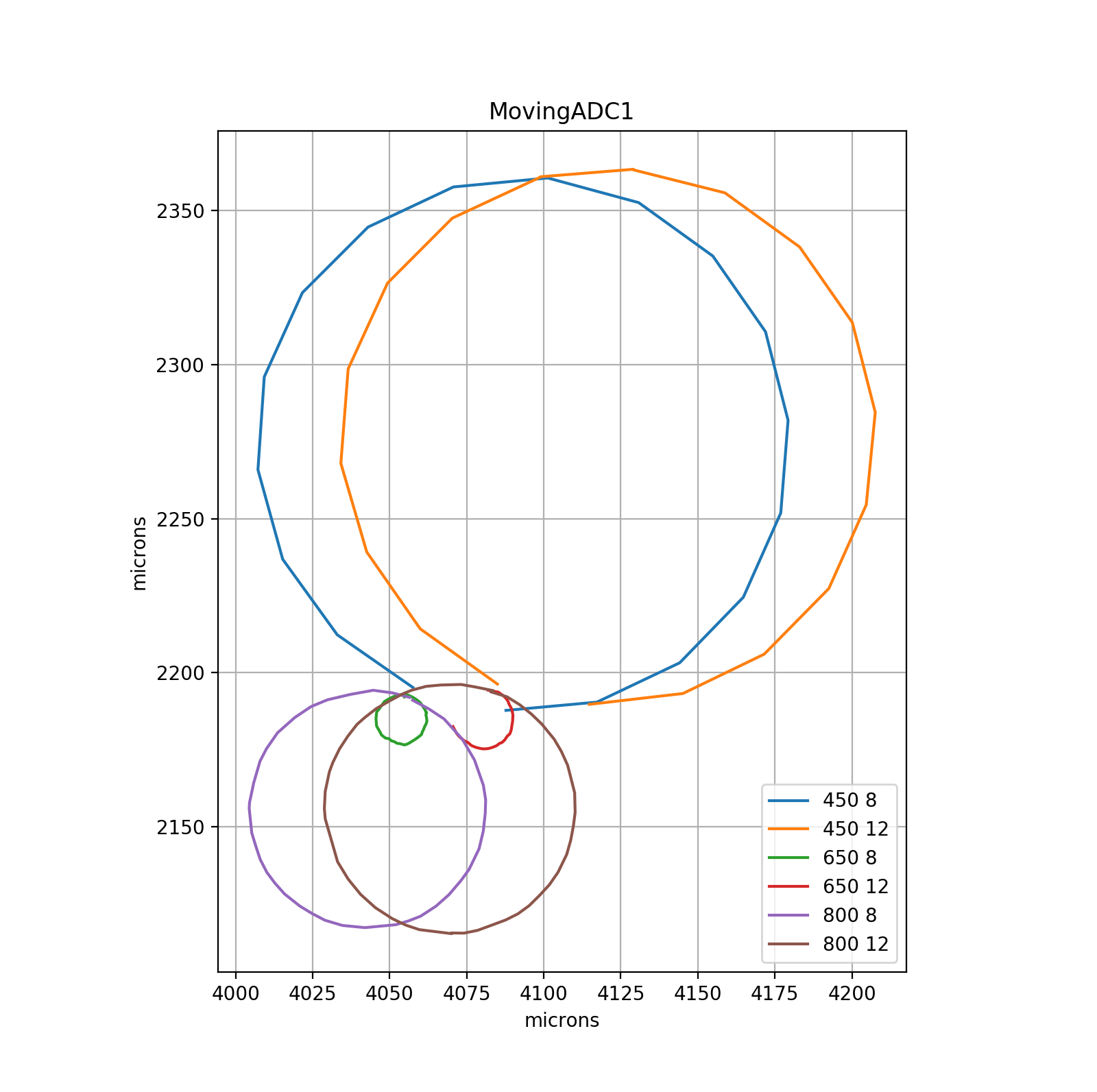
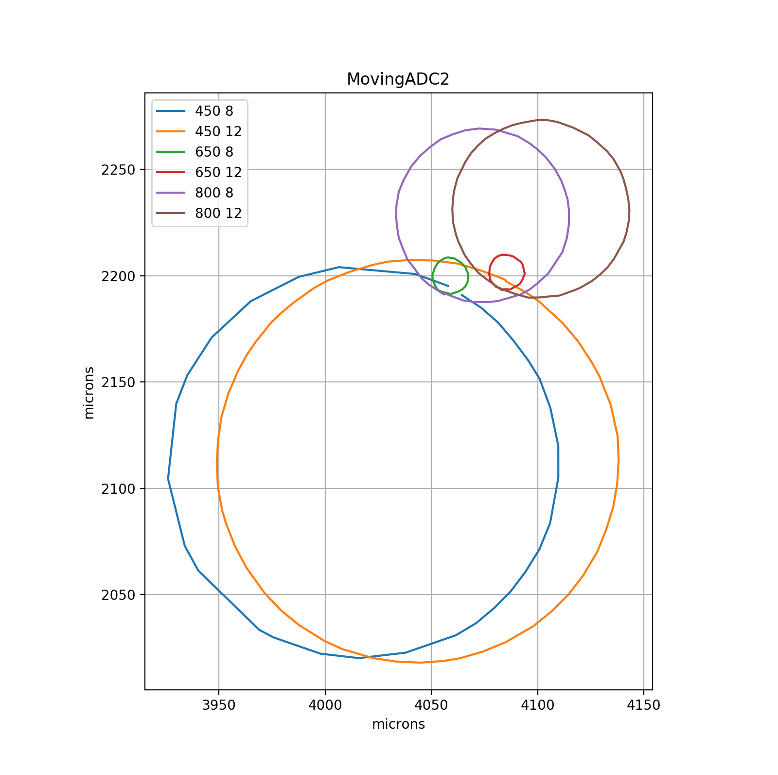
In table 3 are summarized the nominal and actual value for the dispersion at three different wavelength. We moved each motor at time and we took images of the monochromatic spot. The circle drawn by the spot as a radius that strictly depend on the dispersion angle (on sky working will be counter-dispersion) introduced by the ADC for the specific wavelength. In figure 10 the three circle for the 450nm, 650nm and 800nm are visible moving ADC1 or 2. An off-set in the diameter of the circle and so in the exit beam angle is present but very small and well manageable.
| Wavelength | ADC 1 [µm] | ADC 2 [µm] | Nominal [µm] |
|---|---|---|---|
| 450 nm | 86.73 | 92.19 | 102 |
| 650 nm | 8.04 | 8.40 | 0 |
| 800 nm | 38.35 | 40.83 | 32 |
Summarizing, we can say that SOXS’ ADC is now well aligned inside the tolerances and we have defined a valid strategy for aligning a powered ADC.
-
•
Optical quality (encircled energy) and dispersion property are in accordance with ray tracing simulations;
-
•
An alignment and verification strategy for a powered ADC is set;
-
•
The new alignment inside the CP returns 1% error in F/#.
References
- [1] Schipani, P. et al., “The new SOXS instrument for the ESO NTT,” Proc. SPIE 9908, 990841 (2016).
- [2] Claudi, R. et al., “The common path of SOXS (Son of X-Shooter),” Proc. SPIE 10702, 107023T (2018).
- [3] Sanchez, R. Z. et al., “Optical design of the SOXS spectrograph for ESO NTT,” Proc. SPIE 10702, 1070227 (2018).
- [4] Biondi, F. et al., “The AIV strategy of the common path of Son of X-Shooter,” Proc. SPIE 11447, 114476P (2020).
- [5] Rubin, A. et al., “MITS: the Multi-Imaging Transient Spectrograph for SOXS,” Proc. SPIE 10702, 107022Z (2018).
- [6] Schipani, P. et al., “SOXS: a wide band spectrograph to follow up transients,” Proc. SPIE 10702, 107020F (2018).
- [7] Vitali, F. et al., “The NIR spectrograph for the new SOXS instrument at the NTT,” Proc. SPIE 10702, 1070228 (2018).
- [8] Brucalassi, A. et al., “The acquisition camera system for SOXS at NTT,” Proc. SPIE 10702, 107022M (2018).
- [9] Cosentino, R. et al., “The vis detector system of SOXS,” Proc. SPIE 10702, 107022J (2018).
- [10] Ricci, D. et al., “Architecture of the SOXS instrument control software,” Proc. SPIE 10707, 107071G (2018).
- [11] Capasso, G. et al., “SOXS control electronics design,” Proc. SPIE 10707, 107072H (2018).
- [12] Aliverti, M. et al., “The mechanical design of SOXS for the NTT,” Proc. SPIE 10702, 1070231 (2018).
- [13] Biondi, F. et al., “The assembly integration and test activities for the new SOXS instrument at NTT,” Proc. SPIE 10702, 107023D (2018).
- [14] Young, D. et al., “The SOXS data reduction pipeline,” Proc. SPIE 11452, 114522D (2020).
- [15] Kuncarayakti, H. et al., “Design and development of the SOXS calibration unit,” Proc. SPIE 11447, 1144766 (2020).
- [16] Schipani, P. et al., “Development status of the SOXS spectrograph for the ESO-NTT telescope,” Proc. SPIE 11447, 1144709 (2020).
- [17] Genoni, M. et al., “SOXS End-to-End simulator: development and applications for pipeline design,” Proc. SPIE 11450, 114501B (2020).
- [18] Colapietro, M. et al., “Progress and tests on the Instrument Control Electronics for SOXS,” Proc. SPIE 11452, 1145225 (2020).
- [19] Vitali, F. et al., “The development status of the NIR arm of the new SOXS instrument at the ESO/NTT telescope,” Proc. SPIE 11447, 114475N (2020).
- [20] Ricci, D. et al., “Development status of the SOXS instrument control software,” Proc. SPIE 11452, 114522Q (2020).
- [21] Rubin, A. et al., “Progress on the UV-VIS arm of SOXS,” Proc. SPIE 11447, 114475L (2020).
- [22] Cosentino, R. et al., “Development status of the UV-VIS detector system of SOXS for the ESO-NTT telescope,” Proc. SPIE 11447, 114476C (2020).
- [23] Brucalassi, A. et al., “Final design and development status of the acquisition and guiding system for SOXS,” Proc. SPIE 11447, 114475V (2020).
- [24] Sanchez, R. Z. et al., “SOXS: effects on optical performances due to gravity flexures, temperature variations, and subsystems alignment,” Proc. SPIE 11447, 114475F (2020).
- [25] Claudi, R. et al., “Operational modes and efficiency of SOXS,” Proc. SPIE 11447, 114477C (2020).
- [26] Aliverti, M. et al., “Manufacturing, integration and mechanical verification of SOXS,” Proc. SPIE 11447, 114476O (2020).