stefan.loeffler@tuwien.ac.at
ustem]University Service Centre for Transmission Electron Microscopy, TU Wien, Wiedner Hauptstraße 8-10/E057-02, 1040 Wien, Austria
ifp]Institute of Solid State Physics, TU Wien, Wiedner Hauptstraße 8-10/E138-03, 1040 Wien, Austria
ceos]CEOS Corrected Electron Optical Systems GmbH, Englerstraße 28, 69126 Heidelberg, Germany
erc]Ernst Ruska-Centre for Microscopy and Spectroscopy with Electrons (ER-C) and Peter Grünberg Institute, Forschungszentrum Jülich, 52425 Jülich, Germany
rwth]RWTH Aachen University, Ahornstraße 55, 52074 Aachen, Germany
kit]Laboratorium für Elektronenmikroskopie (LEM), Karlsruher Institut für Technologie (KIT), Engesserstraße 7, 76131 Karlsruhe, Germany
A quantum logic gate for free electrons
Abstract
The topological charge of vortex electrons spans an infinite-dimensional Hilbert space. Selecting a two-dimensional subspace spanned by , a beam electron in a transmission electron microscope (TEM) can be considered as a quantum bit (qubit) freely propagating in the column. A combination of electron optical quadrupole lenses can serve as a universal device to manipulate such qubits at the experimenter’s discretion. We set up a TEM probe forming lens system as a quantum gate and demonstrate its action numerically and experimentally. High-end TEMs with aberration correctors are a promising platform for such experiments, opening the way to study quantum logic gates in the electron microscope.
1 Introduction
Manipulating the electron’s phase is a current topic in electron microscopy. On the one hand, wave front engineering promises better spatial resolution [1], novel beam splitters [2], improved sensitivity for particular applications such as spin polarized electronic transitions [3], or manipulating nanoparticles via electron vortex beams [4]. In many respects, the physics of electrons with topological charge is similar to that of photons in singular optics (for an overview see [5]). In particular, quantum logic gates based on photons with orbital angular momentum (OAM) have been successfully demonstrated (e.g. in [6]). Other aspects are unique to electrons, such as easy manipulation in magnetic fields, the extraordinary sub-nm resolution, or novel solid-state applications such as diffraction in chiral crystals [7]. On the other hand, the coherent control of the interaction of fast electrons with electromagnetic radiation, either via near fields in PINEM [8, 9], resonant cavities [10] or laser accelerators [11] leads to oscillations in the probability distribution of the electron’s momentum and energy, allowing the compression of fast electron pulses below the femtosecond time scale.
After the poineering work of Bliokh [12, 13] on electron vortices it took some time for their experimental realization [14, 15]. It was soon shown that they can be manipulated in a magnetic field, giving rise to peculiar rotations [16, 17, 18, 19]. For a review see [20]. The possibility to shape the phase of the electron wave with special holographic masks or via interaction with electromagnetic fields allows not only to prepare single electron wave packets propagating in free space as qubits but also to implement quantum gates for such electrons. This opens the way to design a new platform for quantum operations.
There are many such platforms available, each of them based on a different physical realization of the qubits. Perhaps the best known examples are entangled photon qubits which have been shown to be scalable to some 104 entangled modes [21]; also trapped ion [22] or superconducting [23] qubits were demonstrated. Each of them offers particular benefits and disadavantages. For the time being, it is not clear which of the many experimentally demonstrated implementations will win the race in quantum computing. In recent years, solid state qubits demonstrated promising features in terms of fidelity, scalability or lifetime such as nitrogen-vacancy color centers in diamond (a 10-qubit register that can store quantum information for one minute has recently been demonstrated [24]) or spin qubits based on the well established silicon technology. For overviews, see, e.g., [25, 26].
Recently, an approach towards free electron qubits in the electron microscope, based on energy gain or loss processes using laser-driven near field interactions was proposed [27, 28, 29] but to our knowledge, quantum gates for their manipulation have not yet been realized.
Here, we present proof-of-principle experiments with a quantum gate for freely floating electrons. To this aim, we use a device designed for electron microscopes, called a mode converter (MC) [30] that transforms a plane electron wave into one with topological charge [31, 32]. It should be noted at this point that free floating electron qubits in a TEM are a very novel and emerging field of research. As such, they are not on the level of sophistication of, e.g., photonic qubits that have been researched for decades. In particular, this work deals with the production, manipulation and readout of single qubits. While further concepts such as multi-qubit manipulation and entanglement are briefly discussed, they are essentially beyond the scope of this paper and will require further investigation. Despite the fact that free floating electrons are very new to the scene of quantum information and computing, we strongly believe that they can provide novel insights, particularly in the realm of fundamental research.
2 Theory
2.1 Basis states
In a two-state system, any two orthogonal states can be chosen as a basis for constructing qubits. Preliminary experimental results show that vortex electrons — eigenmodes of the angular momentum operator that are topologically protected and carry quantized OAM of integer multiples of — are very stable during manipulation in the column of a microscope [32]. Therefore, a Hilbert space spanned by two vortex states with topological charge (and linear combinations thereof) is a good candidate for electron qubits.
We use the two Laguerre-Gauss (LG) modes and as basis states [16]. In cylindrical coordinates they have the real-space representations
| (1) | ||||
with
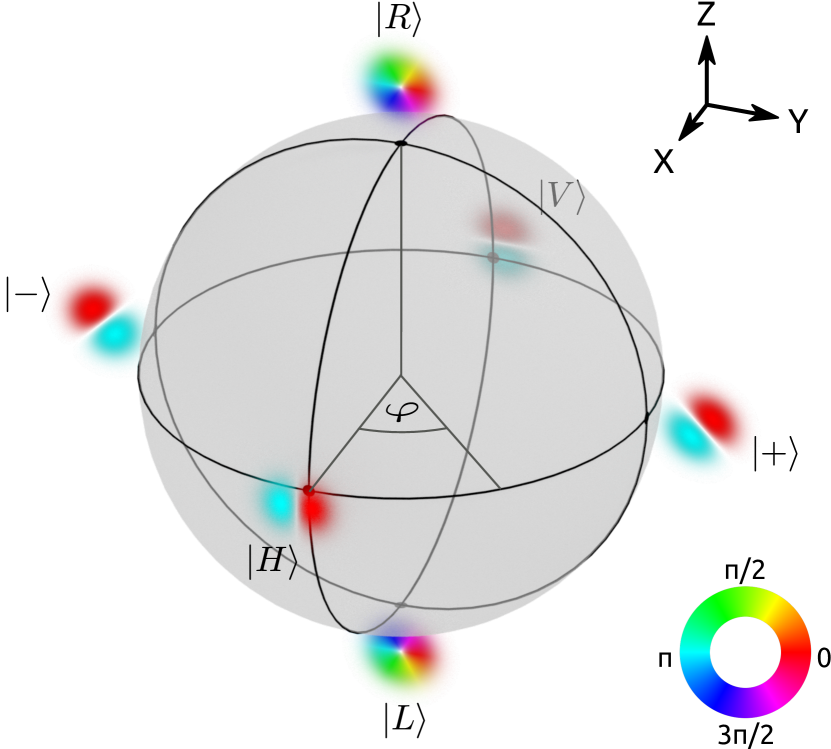
where is a real valued normalization factor. The waist is the propagation dependent beam size, is the Rayleigh length, is the wave number, is the radius of curvature of the wave front, and is the Gouy phase 111It has been pointed out that for non-relativistic electrons the Gouy phase depends on the time at which the propagating wave packet is observed [33], as where is the electron’s speed.. These are diffracting modes, i.e. the radial scale depends on the position of the wave packet along the propagation axis. Note that is considered here as a parameter used for propagation simulation. If not otherwise stated, the qubits are defined in the virtual or real focal planes . The two-dimensional Hilbert space spanned by and is conveniently presented as a Bloch sphere (Fig. 1). Similarly to light optics, we define states
| (2) |
and
| (3) |
Performing qubit operations using a quantum logic gate requires three steps: preparation, manipulation using the gate, and readout, as sketched in Fig. 2.
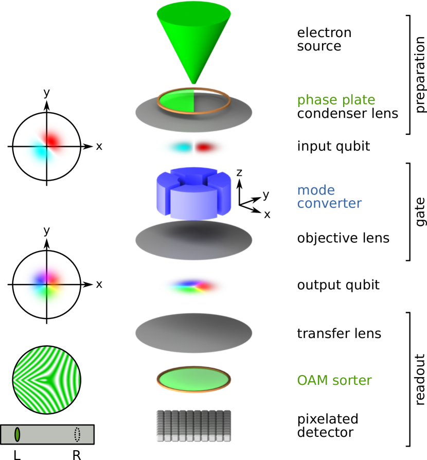
2.2 Qubit preparation
For preparing the input qubit, the electron beam is sent through a phase plate. For the proof-of-principle experiment, we prepare input qubits as states on the equator of the Bloch sphere
| (4) |
with phase shift . Using Eq. 1,
| (5) |
Recalling the definition of Hermite-Gauss (HG) modes
| (6) |
and , Eq. 5 describes a mode rotated by in the plane, except for a global phase factor that is irrelevant for our purpose.
2.3 Qubit manipulation
Manipulation of qubits as prepared above on the Bloch sphere at the experimenter’s discretion can be performed using a set of two quadrupoles (QPs) as used in a MC. All (unitary) manipulations of a qubit correspond to a rotation on the Bloch sphere [30].
In spherical coordinates, a general rotation by an angle around an axis given by the unit vector corresponds to the unitary operator
| (7) |
where is the 3D vector of the Pauli matrices.
The MC performs a rotation of over the axis of the Bloch sphere shown in Fig. 1
| (8) |
Apart from a global phase, this is a quantum gate, usually abbreviated . Note that the axes of the Bloch sphere in Fig. 1 must not be confused with the axes of the real space representation of the states, drawn in Fig. 2.
2.4 Qubit readout
The third step is reading the output qubit. That means projecting it on the basis vectors of the Hilbert space, linked to a measurement device. Technically speaking, in the electron microscope these are pixels on a camera. This is a more subtle problem than it appears. As the intensity distribution of and in position space is identical (a ring), the two states cannot be distinguished and quantified by direct recording.
Therefore, one of the OAM sorters proposed in the literature must be used, from early multi-pinhole interferometers [34] to holographic masks [35] to the more recent OAM unwrappers [36, 37, 38, 39] which are based on a proposal for conformal mapping similar to light optics [40]. Their basis states — in the present case eigenstates of the angular momentum operator — become spatially separated in the sorter222Any readout basis can be selected by rotating the basis of the measurement device on the Bloch sphere into the readout basis. In principle, this can be achieved with a second MC, exactly as described for qubit manipulation..
3 Experimental proof of principle
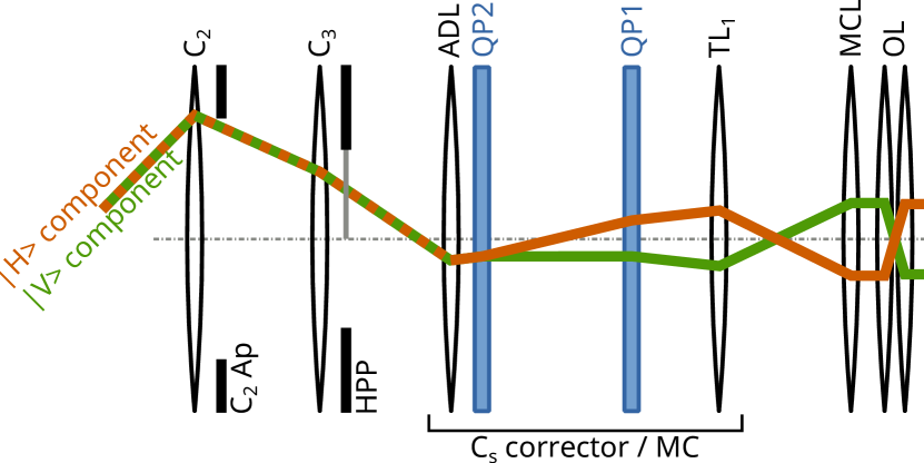
We performed a proof-of-principle experiment on the Jülich PICO microscope, which is a monochromated double-Cs-corrected (S)TEM instrument, together with numerical simulations of the beam propagation [41] to analyze the beam shape and phase in experimentally inaccessible planes such as the MC entrance and exit planes. For this work, only the QPs in the probe-Cs corrector were used to realize the MC [41, 32, 30], i.e., the hexapoles were switched off. A simplified sketch of the general setup and the geometric ray-paths in the probe-forming lens system of the microscope is shown in Fig. 3 [32]. All experiments were carried out at .
3.1 Qubit preparation
Electrons closely resembling HG modes can be produced by several means, e.g., by exploiting the Aharanov-Bohm effect of a magnetic rod [42]. Here, we used a Hilbert phase plate (HPP) [43, 32] inserted in the C3 aperture plane to phase-shift half the incident round beam by . This resulted in a HG-like beam in the focal point, which is located in the input plane of the MC.
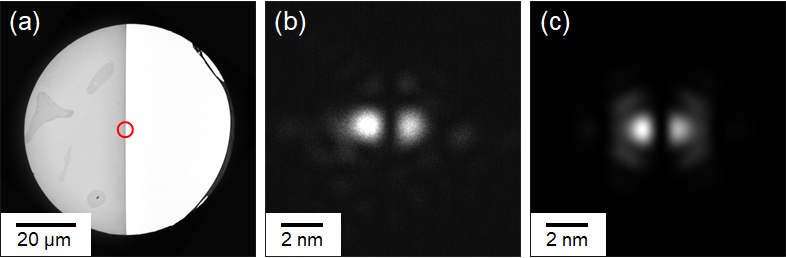
Fig. 4a shows a TEM image of the HPP. It consists of a conventional TEM aperture with a round hole with a diameter of half-covered by an electron-transparent phase-shifting layer system. The layer system consists of a metallic-glass Zirconium-Aluminium alloy (ZAC) covered by amorphous carbon ( and thick, respectively) to prevent oxidization [32]. The thicknesses were chosen to produce the required phase shift for the electrons.
Fig. 4b shows the intensity distribution of the beam in the MC output plane (i.e., the sample plane) for a disabled quantum gate (no quadrupole fields) to gauge the quality of the beam. It clearly is a nice, nano-meter-sized beam, albeit with slight intensity differences of the two lobes, steming from inelastic scattering in the HPP layer. The shape and size are in excellent agreement with the numerical simulations of the same setup, shown in Fig. 4c.
By rotating the MC coordinate system with respect to the HPP axis, arbitrary states can be prepared. In total, we performed four experiments. In our first experiment, we prepared a qubit
| (11) |
by rotating the axis of the MC by with respect to the HPP edge. According to Eq. 5 this is a mode rotated by . In the other experiments, we prepared the qubits
| (12) | ||||
The last two acted as control experiments for the trivial mappings.
3.2 Qubit manipulation
Subsequently, the qubit was sent through the quantum gate realized by the MC. As stated above, the MC was realized by two QPs that were part of the (otherwise disabled) probe Cs corrector. This set of QPs can perform arbitrary unitary transformations on the Bloch sphere by combining two types of operations [30]: (i) a rotation around the Bloch sphere’s axis can be performed by a rotation of the QPs’ coordinate system w.r.t. the input plane, i.e., changing the field axes by changing the current through the magnetic coils333This requires pairs of QPs, though; (ii) a rotation around the Bloch sphere’s axis can be performed by a relative phase shift between the and components (in the QPs’ frame of reference) as one of them goes through a focal point (see ref. 3).
Given the geometry of the microscope, the required focal lengths can be calculated as detailed in [30]. Moreover, the relationship between electric current and focal length can be calibrated for each lens by focusing in specific, fixed planes (e.g., focusing the beam in the sample plane, sharply imaging the various aperture planes, etc.). Once the calibration curves are known, the required focal lengths can easily be set. Note that both the calibration curves and the required focal lengths will vary from instrument to instrument due to slight variations and tolerances in manufacturing.
In our case, we set up the MC such that it acted as an gate. For the four experiments, this resulted in the mappings
| (13) | ||||
as given in Eq. 9.
3.3 Qubit readout
Subsequently, the beam was sent through the objective lens and the projection system and was finally observed on a CCD.
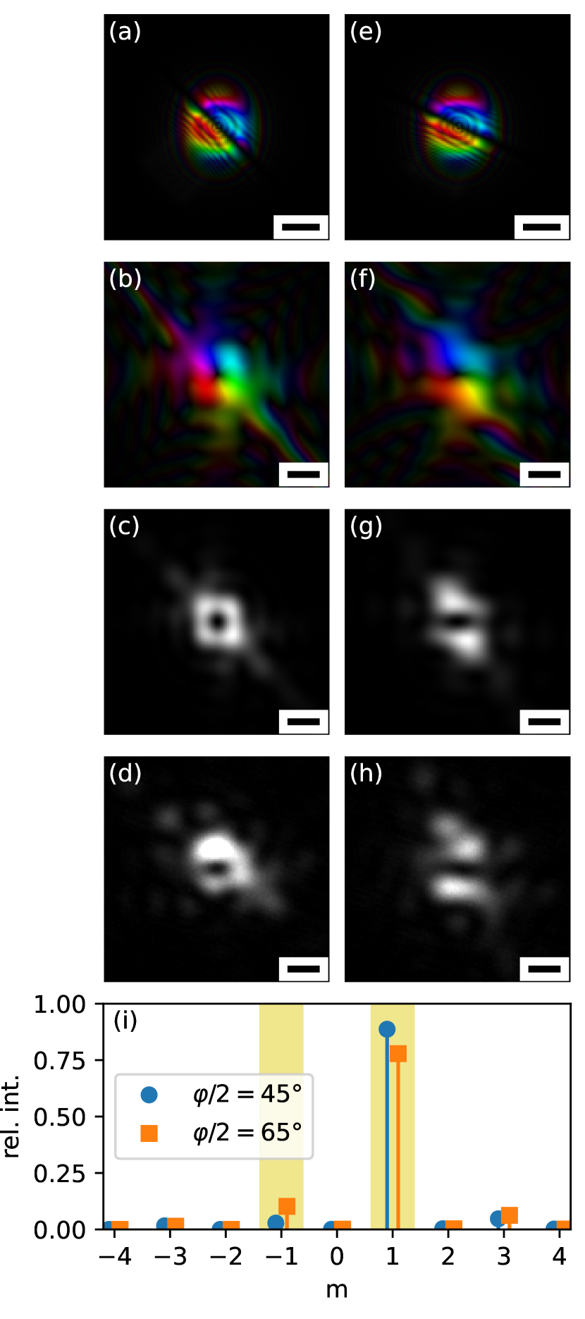
Fig. 5 shows a comparison between the experimental beam in the sample plane and the corresponding simulation of propagation through the column. OAM analysis of the output qubits was done numerically444OAM sorters have been tested successfully elsewhere [36, 37, 38, 39]. Since the implementation of a sorter in the Jülich PICO microscope is currently not feasible we chose a numerical approach (see appendix A).. The results are shown as histogram in Fig. 5. It is clearly visible that (apart from some impurities due to HPP imperfections [32, 41]) the output qubit in the case consists essentially of the component (corresponding to ), whereas in the case, the output qubit features roughly relative intensity of the component (corresponding to ) over the impurity background.
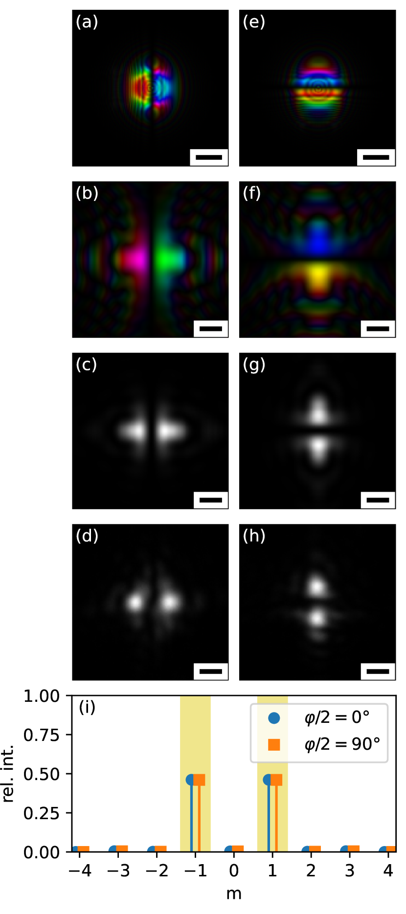
Likewise, Fig. 6 shows the experimental and simulated data for the control experiments with and . It is clearly evident that in both cases, the typical two-lobed structure as well as the orientation is preserved upon passage through the quantum gate, as expected. As any linear operator on a 2D Hilbert space is uniquely defined by its action on two linearly independent (basis) vectors, these results further support the conclusion that the MC acts as a general gate.
4 Discussion and Conclusion
High-end TEMs — instruments of utmost stability, spatial and energy resolution, sophisticated lens systems, ultra sensitive detectors and pulsed electron sources with repetition rates of the order of — provide an ideal scenario to extend qubit manipulation from photons, superconducting circuits or ions to freely floating electrons. This novel platform for the study of qubits has several genuine features: qubits can be tailored from to size; in free space, they are topologically protected [44, 45]; there is no need for cryogenic temperatures; they reveal high decoherence times and essentially no relaxation because the energies of the basis states are identical. Recent work on entanglement in electron microscopy [46, 47, 48, 49, 50, 51, 52] could provide opportunities for 2-qubit gates in non-separable systems.
It is not very likely that free electron qubits will enter the race to quantum computing applications, although deceleration in electrostatic fields could well increase their presently short lifetimes. Their most attractive aspect is perhaps a broad range of tunable perturbations of the qubits via controlled interaction with electromagnetic radiation or matter on their way down the microscope column, in order to study the robustness of quantum gate operations, their fidelity and reliability [28].
Acknowledgements
PS thanks D. Karlovets and P. Hommelhof for valuable comments. SL, TS, and PS gratefully acknowledge financial support by the Austrian Science Fund under the projects P29687-N36 and I4309-N36. CEOS GmbH has received funding from the European Union’s Horizon 2020 research and innovation programme under grant agreement No. 823717-ESTEEM3. PHL and REDB acknowledge funding from European Union’s Horizon 2020 research and innovation programme under grant agreement No. 856538 (“3D MAGiC”). MO, MD and DG acknowledge funding of this work by the German Research Foundation (Deutsche Forschungsgemeinschaft) under contract Ge 841/26. The authors acknowledge TU Wien Bibliothek for financial support through its Open Access Funding Programme.
Appendix A Numerical Calculation of the OAM spectrum
As the OAM operator commutes with the (spherically symmetric) free-space Hamiltonian, it is possible to find a simultaneous eigenbasis for the two operators. As , the real-space angular dependence of those states is given by
With this, all free-space wavefunctions can be written in real-space representation as
and the wave-function’s OAM spectrum is given by
| (14) |
Theoretically, these integrals necessarily converge for all for any normalized . In practice, the integrals are typically evaluated within a bounded region where the wavefunction is non-negligible (and above noise level).
To actually calculate the OAM spectrum, we first transformed the wavefunction to a polar representation , using bilinear interpolation where necessary. Then, we Fourier-transformed with respect to the component [53], resulting in
Finally, the spectrum is given simply by the norm
References
- Rotunno et al. [2019] E. Rotunno, A.H. Tavabi, E. Yucelen, S. Frabboni, R.E. Dunin Borkowski, E. Karimi, B.J. McMorran, and V. Grillo. Electron-beam shaping in the transmission electron microscope: Control of electron-beam propagation along atomic columns. Phys. Rev. Appl., 11(4):044072, April 2019. doi: 10.1103/physrevapplied.11.044072.
- Hammer et al. [2015] J. Hammer, S. Thomas, P. Weber, and P. Hommelhoff. Microwave chip-based beam splitter for low-energy guided electrons. Phys. Rev. Lett., 114(25):254801, 2015. doi: 10.1103/PhysRevLett.114.254801.
- Schachinger et al. [2017] T. Schachinger, S. Löffler, A. Steiger-Thirsfeld, M. Stöger-Pollach, S. Schneider, D. Pohl, B. Rellinghaus, and P. Schattschneider. EMCD with an electron vortex filter: Limitations and possibilities. Ultramicroscopy, 179:15–23, 2017. doi: 10.1016/j.ultramic.2017.03.019.
- Verbeeck et al. [2013] J. Verbeeck, H. Tian, and G. Van Tendeloo. How to manipulate nanoparticles with an electron beam? Adv. Mater., 25(8):1114–1117, 2013. doi: 10.1002/adma.201204206.
- Franke-Arnold et al. [2008] S. Franke-Arnold, L. Allen, and M. Padgett. Advances in optical angular momentum. Laser Photonics Rev., 2(4):299–313, 2008. doi: 10.1002/lpor.200810007.
- Babazadeh et al. [2017] A. Babazadeh, M. Erhard, F. Wang, M. Malik, R. Nouroozi, M. Krenn, and A. Zeilinger. High-dimensional single-photon quantum gates: Concepts and experiments. Phys. Rev. Lett., 119:180510, Nov 2017. doi: 10.1103/PhysRevLett.119.180510.
- Juchtmans et al. [2015] R. Juchtmans, A. Béché, A. Abakumov, M. Batuk, and J. Verbeeck. Using electron vortex beams to determine chirality of crystals in transmission electron microscopy. Phys. Rev. B, 91:094112, Mar 2015. doi: 10.1103/PhysRevB.91.094112.
- Vanacore et al. [2018] G. M. Vanacore, I. Madan, G. Berruto, K. Wang, E. Pomarico, R. J. Lamb, D. McGrouther, I. Kaminer, B. Barwick, F. J. Garcia De Abajo, and F. Carbone. Attosecond coherent control of free-electron wave functions using semi-infinite light fields. Nat. Commun., 9(1):2694, 2018. doi: 10.1038/s41467-018-05021-x.
- Feist et al. [2015] A. Feist, K.E. Echternkamp, J. Schauss, S.V. Yalunin, S. Schäfer, and C. Ropers. Quantum coherent optical phase modulation in an ultrafast transmission electron microscope. Nature, 521(7551):200–203, 2015. doi: 10.1038/nature14463.
- Kealhofer et al. [2016] C. Kealhofer, W. Schneider, D. Ehberger, A. Ryabov, F. Krausz, and P. Baum. All-optical control and metrology of electron pulses. Science, 352(6284):429–433, 2016. doi: 10.1126/science.aae0003.
- Schönenberger et al. [2019] N. Schönenberger, A. Mittelbach, P. Yousefi, J. McNeur, U. Niedermayer, and P. Hommelhoff. Generation and characterization of attosecond microbunched electron pulse trains via dielectric laser acceleration. Phys. Rev. Lett., 123(26):264803, 2019. doi: 10.1103/PhysRevLett.123.264803.
- Bliokh et al. [2007] K. Y. Bliokh, Y. P. Bliokh, S. Savel’ev, and F. Nori. Semiclassical dynamics of electron wave packet states with phase vortices. Phys. Rev. Lett., 99(19), 2007. doi: 10.1103/PhysRevLett.99.190404.
- Bliokh et al. [2011] K. Y. Bliokh, M. R. Dennis, and F. Nori. Relativistic electron vortex beams: Angular momentum and spin-orbit interaction. Phys. Rev. Lett., 107(17), 2011. doi: 10.1103/PhysRevLett.107.174802.
- Verbeeck et al. [2010] J. Verbeeck, H. Tian, and P. Schattschneider. Production and application of electron vortex beams. Nature, 467(7313):301–304, 2010. doi: 10.1038/nature09366.
- Uchida and Tonomura [2010] M. Uchida and A. Tonomura. Generation of electron beams carrying orbital angular momentum. Nat., 464:737–739, 04 2010. doi: 10.1038/nature08904.
- Bliokh et al. [2012] K.Y. Bliokh, P. Schattschneider, J. Verbeeck, and F. Nori. Electron vortex beams in a magnetic field: A new twist on Landau levels and Aharonov-Bohm states. Phys. Rev. X, 2(4):041011, 2012. doi: 10.1103/PhysRevX.2.041011.
- Schattschneider et al. [2014] P. Schattschneider, T. Schachinger, M. Stöger-Pollach, S. Löffler, A. Steiger-Thirsfeld, K. Y. Bliokh, and F. Nori. Imaging the dynamics of free-electron Landau states. Nat. Commun., 5:4586, August 2014. doi: 10.1038/ncomms5586.
- Guzzinati et al. [2013] G. Guzzinati, P. Schattschneider, K. Y. Bliokh, F. Nori, and J. Verbeeck. Observation of the Larmor and Gouy Rotations with Electron Vortex Beams. Phys. Rev. Lett., 110:093601, February 2013. doi: 10.1103/PhysRevLett.110.093601.
- Schachinger et al. [2015] T. Schachinger, S. Löffler, M. Stöger-Pollach, and P. Schattschneider. Peculiar rotation of electron vortex beams. Ultramicroscopy, 158:17–25, November 2015. ISSN 0304-3991. doi: 10.1016/j.ultramic.2015.06.004.
- Bliokh et al. [2017] K. Y. Bliokh, I. P. Ivanov, G. Guzzinati, L. Clark, R. Van Boxem, A. Béché, R. Juchtmans, M. A. Alonso, P. Schattschneider, F. Nori, and J. Verbeeck. Theory and applications of free-electron vortex states. Phys. Rep., 690:1–70, 2017. doi: 10.1016/j.physrep.2017.05.006.
- Larsen et al. [2019] M. V. Larsen, X. Guo, C. R. Breum, J. S. Neergaard-Nielsen, and U. L. Andersen. Deterministic generation of a two-dimensional cluster state. Science, 366(6463):369–372, 2019. doi: 10.1126/science.aay4354.
- Brown et al. [2021] K. R. Brown, J. Chiaverini, J. M. Sage, and H. Häffner. Materials challenges for trapped-ion quantum computers. Nat. Rev. Mater., 6(10):892–905, 2021. doi: 10.1038/s41578-021-00292-1.
- Kjaergaard et al. [2020] M. Kjaergaard, M. E. Schwartz, J. Braumüller, P. Krantz, J. I. . Wang, S. Gustavsson, and W. D. Oliver. Superconducting qubits: Current state of play. Annu. Rev. Conden. Ma. P., 11:369–395, 2020. doi: 10.1146/annurev-conmatphys-031119-050605.
- Bradley et al. [2019] C. E. Bradley, J. Randall, M. H. Abobeih, R. C. Berrevoets, M. J. Degen, M. A. Bakker, M. Markham, D. J. Twitchen, and T. H. Taminiau. A ten-qubit solid-state spin register with quantum memory up to one minute. Phys. Rev. X, 9(3), 2019. doi: 10.1103/PhysRevX.9.031045.
- Buluta et al. [2011] I. Buluta, S. Ashhab, and F. Nori. Natural and artificial atoms for quantum computation. Rep. Prog. Phys., 74(10):104401, sep 2011. doi: 10.1088/0034-4885/74/10/104401.
- Chatterjee et al. [2021] A. Chatterjee, P. Stevenson, S. De Franceschi, A. Morello, N. P. de Leon, and F. Kuemmeth. Semiconductor qubits in practice. Nature Reviews Physics, 3(3):157–177, 2021. doi: 10.1038/s42254-021-00283-9. Cited By :91.
- Reinhardt et al. [2021] O. Reinhardt, C. Mechel, M. Lynch, and I. Kaminer. Free-electron qubits. Ann. Phys., 533(2):2000254, 2021. doi: 10.1002/andp.202000254.
- Ruimy et al. [2021] R. Ruimy, A. Gorlach, C. Mechel, N. Rivera, and I. Kaminer. Toward atomic-resolution quantum measurements with coherently shaped free electrons. Phys. Rev. Lett., 126(23):233403, jun 2021. doi: 10.1103/physrevlett.126.233403.
- Tsarev et al. [2021] M. V. Tsarev, A. Ryabov, and P. Baum. Free-electron qubits and maximum-contrast attosecond pulses via temporal talbot revivals. Phys. Rev. Research, 3(4):043033, oct 2021. doi: 10.1103/physrevresearch.3.043033.
- Löffler [2022] S. Löffler. Unitary two-state quantum operators realized by quadrupole fields in the electron microscope. Ultramicroscopy, 234:113456, 2022. doi: 10.1016/j.ultramic.2021.113456.
- Schattschneider et al. [2012] P. Schattschneider, M. Stöger-Pollach, and J. Verbeeck. Novel vortex generator and mode converter for electron beams. Phys. Rev. Lett., 109(8):084801, 2012. doi: 10.1103/PhysRevLett.109.084801.
- Schachinger et al. [2021] T. Schachinger, P. Hartel, P. Lu, S. Löffler, M. Obermair, M. Dries, D. Gerthsen, R. E. Dunin-Borkowski, and P. Schattschneider. Experimental realisation of a vortex mode converter for electrons using a spherical aberration corrector. Ultramicroscopy, 229:113340, 2021. doi: 10.1016/j.ultramic.2021.113340.
- Karlovets [2018] D. Karlovets. Relativistic vortex electrons: Paraxial versus nonparaxial regimes. Phys. Rev. A, 98:012137, Jul 2018. doi: 10.1103/PhysRevA.98.012137.
- Clark et al. [2014] L. Clark, A. Béché, G. Guzzinati, and J. Verbeeck. Quantitative measurement of orbital angular momentum in electron microscopy. Physical Review A - Atomic, Molecular, and Optical Physics, 89(5):053818, 2014. doi: 10.1103/PhysRevA.89.053818.
- Guzzinati et al. [2014] G. Guzzinati, L. Clark, A. Béché, and J. Verbeeck. Measuring the orbital angular momentum of electron beams. Physical Review A - Atomic, Molecular, and Optical Physics, 89(2):025803, 2014. doi: 10.1103/PhysRevA.89.025803.
- McMorran et al. [2017] B. J. McMorran, T. R. Harvey, and M. P. J. Lavery. Efficient sorting of free electron orbital angular momentum. New J. Phys., 19(2):023053, 2017. doi: 10.1088/1367-2630/aa5f6f.
- Grillo et al. [2017] V. Grillo, A. H. Tavabi, F. Venturi, H. Larocque, R. Balboni, G. C. Gazzadi, S. Frabboni, P. . Lu, E. Mafakheri, F. Bouchard, R. E. Dunin-Borkowski, R. W. Boyd, M. P. J. Lavery, M. J. Padgett, and E. Karimi. Measuring the orbital angular momentum spectrum of an electron beam. Nat. Commun., 8:15536, 2017. doi: 10.1038/ncomms15536.
- Pozzi et al. [2020] G. Pozzi, V. Grillo, P. Lu, A. H. Tavabi, E. Karimi, and R. E. Dunin-Borkowski. Design of electrostatic phase elements for sorting the orbital angular momentum of electrons. Ultramicroscopy, 208:112861, 2020. doi: 10.1016/j.ultramic.2019.112861.
- Tavabi et al. [2021] A. H. Tavabi, P. Rosi, E. Rotunno, A. Roncaglia, L. Belsito, S. Frabboni, G. Pozzi, G. C. Gazzadi, P. Lu, R. Nijland, M. Ghosh, P. Tiemeijer, E. Karimi, R. E. Dunin-Borkowski, and V. Grillo. Experimental demonstration of an electrostatic orbital angular momentum sorter for electron beams. Phys. Rev. Lett., 126(9):094802, mar 2021. doi: 10.1103/physrevlett.126.094802.
- Berkhout et al. [2010] G. C. G. Berkhout, M. P. J. Lavery, J. Courtial, M. W. Beijersbergen, and M. J. Padgett. Efficient sorting of orbital angular momentum states of light. Phys. Rev. Lett., 105(15):153601, 2010. doi: 10.1103/PhysRevLett.105.153601.
- Kramberger et al. [2019] C. Kramberger, S. Löffler, T. Schachinger, P. Hartel, J. Zach, and P. Schattschneider. /2 mode converters and vortex generators for electrons. Ultramicroscopy, 204:27–33, September 2019. doi: 10.1016/j.ultramic.2019.05.003.
- Béché et al. [2013] A. Béché, R. Van Boxem, G. Van Tendeloo, and J. Verbeeck. Magnetic monopole field exposed by electrons. Nat. Phys., 10(1):26–29, December 2013. ISSN 1745-2481. doi: 10.1038/nphys2816.
- Dries et al. [2018] M. Dries, M. Obermair, S. Hettler, P. Hermann, K. Seemann, F. Seifried, S. Ulrich, R. Fischer, and D. Gerthsen. Oxide-free aC/\ceZr_0.65Al_0.075Cu_0.275/aC phase plates for transmission electron microscopy. Ultramicroscopy, 189:39–45, jun 2018. doi: 10.1016/j.ultramic.2018.03.003.
- Lubk et al. [2013] A. Lubk, L. Clark, G. Guzzinati, and J. Verbeeck. Topological analysis of paraxially scattered electron vortex beams. Phys. Rev. A, 87:033834, March 2013. doi: 10.1103/PhysRevA.87.033834.
- Kitaev [2003] A. Y. Kitaev. Fault-tolerant computation by anyons. Ann. Phys., 303:2–30, 2003. doi: 10.1016/S0003-4916(02)00018-0.
- Okamoto [2014] H. Okamoto. Measurement errors in entanglement-assisted electron microscopy. Physical Review A - Atomic, Molecular, and Optical Physics, 89(6):063828, 2014. doi: 10.1103/PhysRevA.89.063828.
- Schattschneider and Löffler [2018] P. Schattschneider and S. Löffler. Entanglement and decoherence in electron microscopy. Ultramicroscopy, 190:39–44, 2018. doi: 10.1016/j.ultramic.2018.04.007.
- Schattschneider et al. [2020] P. Schattschneider, S. Löffler, H. Gollisch, and R. Feder. Entanglement and entropy in electron–electron scattering. J. Electron Spectrosc. Relat. Phenom., 241:146810, 2020. doi: 10.1016/j.elspec.2018.11.009.
- Haindl et al. [2023] R. Haindl, A. Feist, T. Domröse, M. Möller, J. H. Gaida, S. V. Yalunin, and C. Ropers. Coulomb-correlated electron number states in a transmission electron microscope beam. Nature Physics, 2023. doi: 10.1038/s41567-023-02067-7.
- Meier et al. [2023] S. Meier, J. Heimerl, and P. Hommelhoff. Few-electron correlations after ultrafast photoemission from nanometric needle tips. Nature Physics, 2023. doi: 10.1038/s41567-023-02059-7.
- Scheucher et al. [2022] M. Scheucher, T. Schachinger, T. Spielauer, M. Stöger-Pollach, and P. Haslinger. Discrimination of coherent and incoherent cathodoluminescence using temporal photon correlations. Ultramicroscopy, 241:113594, nov 2022. doi: 10.1016/j.ultramic.2022.113594.
- Konečná et al. [2022] A. Konečná, F. Iyikanat, and F. J. García de Abajo. Entangling free electrons and optical excitations. Sci. Adv., 8(47):eabo7853, nov 2022. doi: 10.1126/sciadv.abo7853.
- Löffler et al. [2019] S. Löffler, S. Sack, and T. Schachinger. Elastic propagation of fast electron vortices through amorphous materials. Acta Crystallogr. A, 75(6):902–910, 2019. doi: 10.1107/S2053273319012889.