Beamline Volume Relief Analysis for the PIP-II SSR2 Cryomodule at Fermilab ††thanks: This manuscript has been authored by Fermi Research Alliance, LLC under Contract No. DE-AC02-07CH11359 with the U.S. Department of Energy, Office of Science, Office of High Energy Physics.
Abstract
The beam volume of the Pre-Production Single Spoke Resonator type 2 (ppSSR2) cryomodule[1] for the Proton Improvement Plan-II (PIP-II)[2] project will be protected against over-pressurization using a burst disk. This contribution focuses on the analysis of the relief of such trapped volume during a catastrophic scenario with multiple systems failures. An analytical model, able to predict the pressure in the beam volume depending of the various boundary conditions, has been developed and will be presented along with the results.
1 INTRODUCTION
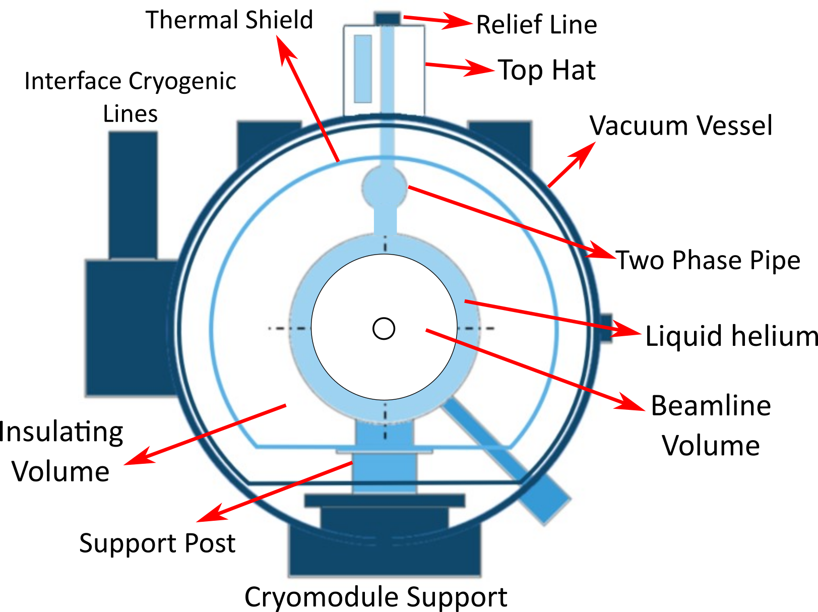
Superconducting Radio Frequency (SRF) cavities are the core of linear particle accelerators like PIP-II. The new pre-production SSR2 (ppSSR2) cavities [3], [4], [5] as well as Single Spoke Resonator Type 1 (SSR1) [6], Low Beta (LB) [8] and High Beta (HB) [9] 650 MHz cavities and cryomodules [7] for PIP-II use liquid helium to cool the SRF cavities down to 2K in order to harness the superconducting advantages. Fig. 1 shows a generic section, transversal to the beam axis, of a PIP-II cryomodule. In operation the insulating volume and beamline volume are under vacuum (high vacuum and ultra-high vacuum respectively). The support post is made of insulating material and interface room temperature with the beamline components at 2K. The liquid helium is contained in a circuit that encompasses the beamline components and at the operating temperature of 2K is in a two-phase state. The circuit is connected with relief devices installed outside the vacuum vessel that are set to relieve the pressure above 4.1 bar-g when in operation. A thermal shield, maintained at a temperature around 50K screen the beamline components from the radiation coming from the vacuum vessel. A leak between the liquid helium circuit and the beamline volume may occur during the life of the PIP-II project. If this leak goes undetected, liquid helium may accumulate in the beamline volume. Once the insulating vacuum is spoiled the liquid helium trapped in the beamline volume may vaporize rapidly increasing the pressure in this space. To protect the cavities and beamline components from over-pressure, a burst disk is installed on the beamline outside of the cryomodule.
2 INPUTS AND ASSUMPTIONS
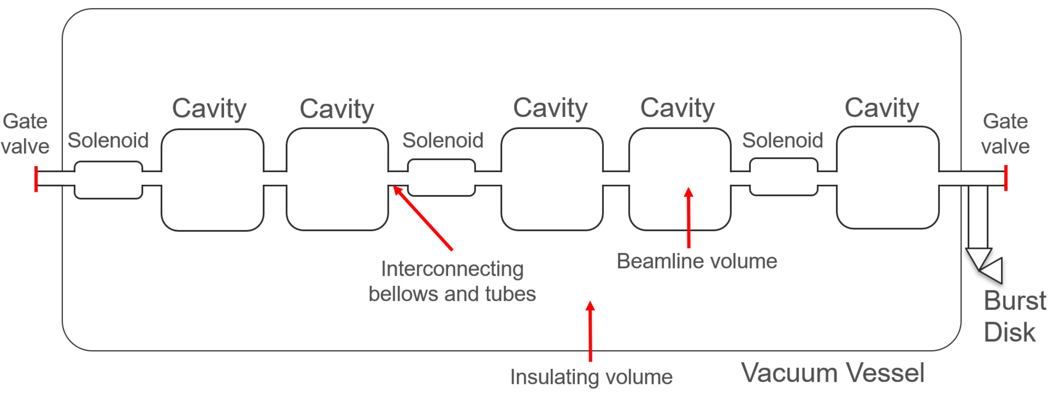
To purpose of this work is to analytically evaluate the pressure inside the beamline volume as a function of the time given the applied boundary conditions under certain assumptions. Fig. 2 schematically shows the main elements that are recalled in this section. The inputs used for the calculation are therefore:
-
•
Geometry: the ppSSR2 cryomodule is chosen as geometry for the analysis. It includes 5 cavities and 3 solenoids connected by bellows and tubes. The solenoid beamline volume has the same shape and Internal Diameter (ID) of the interconnecting elements therefore it will be considered as straight pipe and the cavities are modeled as cylinders for the purpose of this analysis. The beamline volume is considered to be closed by 2 gate valves at each ends. The beamline volume is interfacing the insulting volume (the helium circuit is not included. This is a conservative assumption). The complex geometry that goes from the beamline to the burst disk is decomposed in several elemental shapes for which the resistance coefficient can be easily calculated.
-
•
Defect: a defect with a determined leak rate connects the helium circuit with the textitbeamline volume. Liquid helium fills the volume for a certain amount of time.
-
•
Heat load to helium: the insulating vacuum is lost in 1 minute of time. As a consequence, a convective heat load is establish between the air in that volume and the helium. The presence of a thermal shield is also neglected and the helium therefore sees a radiative heat load from underline300K. The conductive heat load from the support posts is included as well. All these heat loads are absorbed 100% by the helium.
All the described assumptions and the one used as part of the calculation to establish diameter changes, simplify the geometry, etc. are conservative and contribute to increase the pressure in the system. This is done on purpose so that, even if the developed mathematical model is intrinsically inaccurate because unable to capture the complexity of the geometry and heat transfer mechanisms, the result represents the worst case possible in the presence of the most unfavorable conditions.
3 PROBLEM DESCRIPTION
Given the underlinegeometry of the beamline volume, the underlineleak rate and the underlinetime during which the leak goes undetected (6 months which equals to 2 warm-ups of the cryomodule each year) is possible to calculate the volume of liquid helium at the initial condition. At t = 0 s:
-
•
the insulating volume pressure start rising rises with an exponential law so that at t = 60 s the pressure is within 5% of the atmospheric pressure.
-
•
liquid helium and vapor coexist in the closed beamline volume at the temperature of 2.17K and correspondent saturation pressure (all thermophysical properties are taken from the National Institute of Standards and Technology (NIST) [10]
-
•
Heat from convection, radiation and conduction starts to transfer in the closed helium system. The convection and radiation contributes depends on the temperature of the helium, the conduction contribution is orders of magnitude smaller compared to the convection therefore it is assumed constant an equal to the maximum possible throughout the calculation (8 W total)
As a result of the heat load, the temperature and pressure of the closed system increases until all liquid helium evaporate and, as the pressure reaches the burst disk set point, the system opens and the helium starts to flow outside.
At t > 0 s, the temperature and pressure of the helium can be calculated imposing the energy balance and using the Van der Waals equations when the helium is outside the saturation vapor curve or extracting the saturation pressure at a given temperature when both the liquid and vapor phases co-exists. A code is written that solves the system of eqs. 1 in an iterative manner at each time step. Where: is the convective heat, is the heat from radiation, is the heat from conduction, is the mass of helium in the system, is the helium mass flow rate exiting the system, is the specific heat constant for helium, is the helium temperature, is the heat transported out of the system from the helium, is the helium volume, and are gas constants, is the number of moles and is the gas constant.
| (1) |
| (2) |
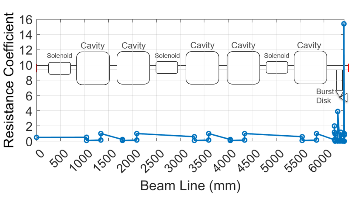
Where represents the sum of the ratio between the resistance coefficients at each section and (where is the local outlet diameter at the end of each section) along the relief line, represnet the fluid density and the outlet diameter. is the net expansion factor and in this case, for helium gas and for a choked flow, is set to 0.6 which represent a conservative assumption. Fig. 3 shows the resistance coefficient along the beam line. The last portion, which includes several tees and diameter changes through valves as well as the burst disk dominate the contribution.
3.1 Heat Transfer
The convective heat transfer from the air to the helium are calculated simplifying the geometry in a basic shape (cylinder) with different diameter depending on the element: cavity, solenoid or beam tube. The equation for the Nusselt number for natural convection around a cylinder is taken from [13] and it is shown in eq. 3 where and are the Rayleigh an Prandtl number respectively. The thermophysical properties of air are also taken from the NIST [10].
| (3) |
The contribution of the flat faces of the cylinders are also considered in the calculation using the appropriate formula for the Nusselt number (proportional to the Rayleigh and Prandtl numbers) also taken from [13].
The heat load to the helium is then simply calculated using eq. 4:
| (4) |
Where is the heat transfer coefficient proportional to the appropriate Nusselt number, is the surface and is the temperature difference from ambient to helium.
The radiation heat transfer is calculated from eq. 5
| (5) |
Where is the emissivity, is the Boltzmann constant and is the temperature. Whilst this contribution is included in the calculation, even considering 1 layer of Multi Layer Insulation (MLI) the radiative heat transfer is negligible compared to the convective heat transfer.
The conduction heat transfer through the solenoids is simply calculated with the appropriate material properties and the geometry (tube) using Fourier’s law. As for the radiation heat transfer this contribution is included in the calculation but is negligible even compared to the radiation heat transfer.
4 RESULTS
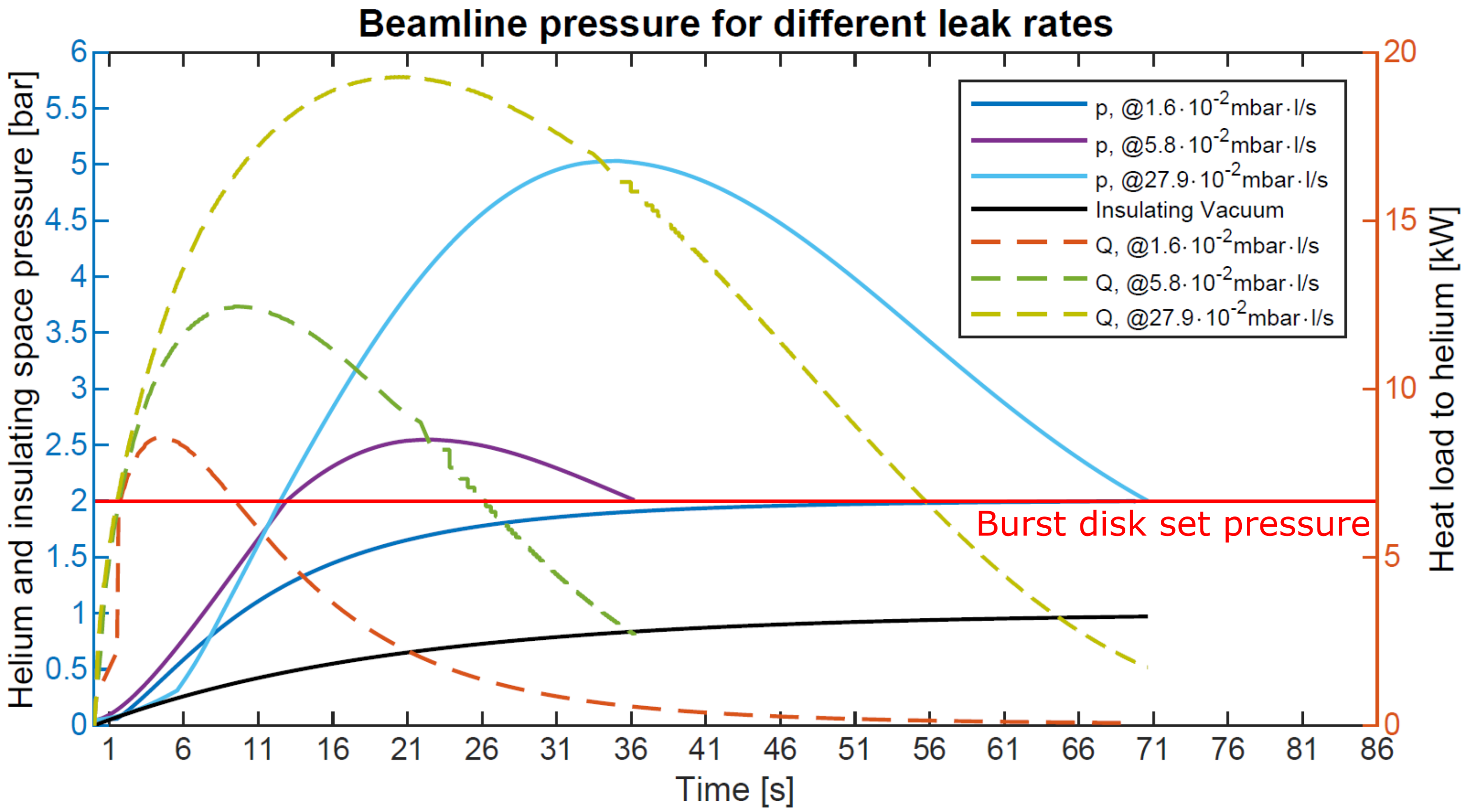
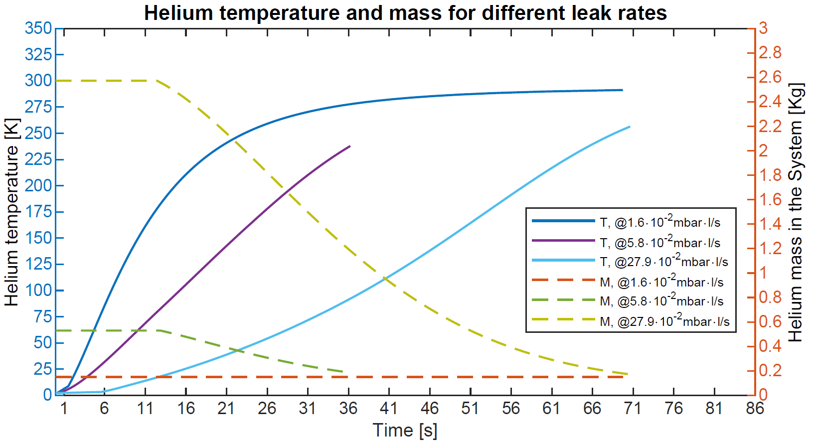
Figs. 4 and 5 shows the results of the analytical calculation. A total of 3 different leak rates are selected ranging from to . The burst disk set pressure is also noted in fig. 4 (1 bar above atmosphere). The leak size below which the burst disk does not open corresponds to . In this case the pressure rises until the burst disk set point and the temperature continue to rise until it reaches the ambient temperature. In correspondence of the biggest leak size selected, the pressure rises until approximately 5.1 bar absolute, which corresponds to 4.1 bar across the thickness of the cavity material. This represent the Maximum Allowable Working Pressure (MAWP) for the PIP-II cavities at cryogenic temperature and therefore this is the limit pressure allowed to consider the system safe. In the figures is also possible to appreciate the heat load transferred to the helium, the trend of the pressure in the insulating vacuum (Fig. 4) and the mass of the helium in the system (Fig. 5).
5 CONCLUSION
From the results, given: the selected burst disk, the beamline volume geometry and the conservative assumptions, the leak rate of the defect above which the safety operation of the ppSSR2 cryomodule is compromised is . All the beamline components go through rigorous inspections at multiple steps of the fabrication and assembly operations, including leak checks performed using an helium mass spectrometer leak detector with a sensitivity better than . Given that there are no dynamic loads during operation, that the applied thermal cycle goes from room temperature to cryogenic operation (thus closing any possible crack or defect), the leak checks performed before operating the machine and the time considered during which the leak goes undetected (6 months), it is safe to assume that such defect, even if present will not compromise the structure and that the burst disk is correctly sized.
References
- [1] J. Bernardini et al., Final Design of Pre-Production SSR2 Cryomodule for PIP-II Project at Fermilab, presented at LINAC2022, TUPOGE12, Liverpool, United Kingdom, Aug-Sep. 2022
- [2] Proton Improvement Plan-II, https://pip2.fnal.gov/
- [3] P. Berrutti et al., New Design of SSR2 Spoke Cavity for PIP II SRF Linac, presented at the 19th Int. Conf. RF Superconductivity (SRF’19), Dresden, Germany, Jun.-Jul. 2019, paper TUP066.
- [4] M. Parise et al., Mechanical Design and Fabrication Aspects of Prototype SSR2 Jacketed Cavities, Proceedings of SRF2019, TUP014, Dresden, Germany, Jun.-Jul. 2019
- [5] M. Parise et al., Fabrication Experience of the Pre-Production PIP-II SSR2 Cavities at Fermilab, presented at LINAC2022, TUPOGE17, Liverpool, United Kingdom, Aug-Sep. 2022
- [6] D. Passarelli et al., Test results of the prototype SSR1 cry-omodule for PIP-II at Fermilab, In Proc IPAC’21, Campinas, Brazil, May 2021, pp. 4461-4465. doi:10.18429/JACoW-IPAC2021-THPAB343
- [7] V. Roger et al., Design strategy of the PIP-II cryomodules, In Proc SRF’19, Dresden, Germany, Jun. 2019, pp. 307-310. doi:10.18429/JACoW-SRF2019-MOP094
- [8] N. Bazin et al., The 650 MHz low beta cryomodule for the PIP-II project, presented at IPAC’22, Bangkok, Thailand, Jun. 2022, paper TUPOTK001, unpublished.
- [9] V. Roger et al., Design of the 650 MHz high beta proto-type cryomodule for PIP-II at Fermilab, presented at SRF’21, Michigan state university, USA, Jun.-Jul. 2021, pa-per WEPTEV015, unpublished.
- [10] Data from NIST Standard Reference Database 69: NIST Chemistry WebBook
- [11] ASME Boiler & Pressure Vessel Code
- [12] Crane Technical Paper No. 410: Flow of Fluids Through Valves, Fittings and Pipe
- [13] A. Bejan, Convection Heat Transfer 4th ed.