Geometric Signatures of Switching Behavior in Mechanobiology
Abstract
The proteins involved in cells’ mechanobiological processes have evolved specialized and surprising responses to applied forces. Biochemical transformations that show catch-to-slip switching and force-induced pathway switching serve important functions in cell adhesion, mechano-sensing and signaling, and protein folding. We show that these switching behaviors are generated by singularities in the flow field that describes force-induced deformation of bound and transition states. These singularities allow for a complete characterization of switching mechanisms in 2-dimensional (2D) free energy landscapes, and provide a path toward elucidating novel forms of switching in higher dimensional models. Remarkably, the singularity that generates a catch-slip switch occurs in almost every 2D free energy landscape, implying that almost any bond admitting a 2D model will exhibit catch-slip behavior under appropriate force. We apply our analysis to models of P-selectin and antigen extraction to illustrate how these singularities provide an intuitive framework for explaining known behaviors and predicting new behaviors.
At the molecular level, mechanobiology involves a wide range of mechanical interactions between proteins that mediate cells’ internal processes and their interactions with their surroundings Stirnemann (2022). These proteins have evolved to respond to applied force in specialized and counter-intuitive ways. Non-covalent bonds that become stronger under an applied pulling force have been found in diverse biological contexts, from cell adhesion and signaling Sokurenko et al. (2008); McEver (2015); Chakrabarti et al. (2017); Zhu et al. (2019), to molecular motors Guo and Guilford (2006); Leidel et al. (2012); Rai et al. (2013); Nord et al. (2017), proofreading Brockman and Salaita (2019) and antigen discrimination Zhu et al. (2019); Choi et al. (2022); Knežević et al. (2018); Jiang and Wang (2022a, b). Such bonds show catch behavior (bond lifetime increases with force) over some range of forces and slip behavior (bond lifetime decreases with force) over some other range of forces. The precise nature of the switch from catch to slip (e.g. the force at which this switch occurs) can be critical to the bond’s biological function Guo and Guilford (2006); Wu et al. (2019), and one expects this switch to be tuned through evolution.
Another form of force-induced switching appears when a transformation can occur via multiple pathways: one pathway may be energetically favorable at low force, while another is favorable at higher force. This alternative form of switching also serves important functions (e.g. antigen extraction Spillane and Tolar (2018); Wang (2021); Jiang and Wang (2022a, b) and protein folding under force Graham and Best (2011); Guinn et al. (2015); Wales and Head-Gordon (2012); Pierse and Dudko (2017); Jagannathan et al. (2012)). Pathway switching and catch-slip switching often appear together in the literature Makarov (2016); Zhuravlev et al. (2016); Suzuki and Dudko (2011), in part because pathway switching can (though does not necessarily) generate a catch-slip switch Bartolo et al. (2002); Evans et al. (2004); Pereverzev et al. (2005). This suggests the possibility of a unified theory for which catch-slip and pathway switching are special cases.
Early conceptual and phenomenological models of catch bonds (e.g. the two-state model Barsegov and Thirumalai (2005); Chakrabarti et al. (2017), two-pathway model Evans et al. (2004); Pereverzev et al. (2005), allosteric model Sokurenko et al. (2008), sliding-rebinding model Lou and Zhu (2007)) have had success explaining many experimental observations. More recent theoretical considerations have revealed that multi-dimensionality of the bond’s free energy landscape is necessary for catch-slip behavior Zhuravlev et al. (2016); Suzuki and Dudko (2010); Makarov (2016). In particular, the deformation of bound state and transition state (i.e. the movement of minimum and saddle points through configuration space) under applied force can generate a variety of catch-slip behaviors Suzuki and Dudko (2011); Konda et al. (2013); Quapp and Bofill (2016); Chakrabarti et al. (2014); Adhikari et al. (2018) and force-history dependence Kong et al. (2013); Chen et al. (2015); Li et al. (2016) in simple 2-dimensional course-grained free energy landscapes. With many 2-dimensional models of catch-slip behavior now known, we are led to ask: how generic is this switching behavior? Are there features of free energy landscapes that indicate a switch?
We discover geometric signatures of catch-slip and pathway switching behavior in the form of singularities in the flow field that describes force-induced deformation of minimum and saddle points. These singularities, which we call “switch points”, can be viewed as the basic building blocks of force-induced switching behavior in two dimensional systems. Using this framework, we show that virtually every 2-dimensional bond will exhibit catch-slip behavior under an appropriate force and/or stress. In higher dimensions, the generalization of switch points indicate other, more exotic, responses to force.
Switch points provide a unified view of known switching mechanisms, and we show how established catch bond models can be understood using switch points. Furthermore, switch points serve as a guide to elucidate new possibilities and make new predictions. We illustrate their utility with a model of the P-Selectin catch bond and a generalized model of the ‘tug-of-war’ process in which B-cells probe antigen specificity via a pathway switch.
Bond rupture under applied force — Consider a system described by a two-dimensional vector governed by a free energy landscape (or potential of mean force) . The external force couples linearly to along a direction and with magnitude . We suppose that the coupling direction is fixed while the magnitude is varied, so that the total potential is
| (1) |
A potential describing a meta-stable bond must have a local minimum corresponding to the bonded state, and one or more saddle points which correspond to pathways along which bond rupture can occur. For a single pathway, the bond lifetime can be approximated using Langer’s formula where the energy barrier is the difference in between the minimum and saddle and the prefactor captures entropic effects of the minimum and saddle Langer (1969). When there are multiple pathways, the lifetime is approximately where , the mean first passage time over pathway , is given by Langer’s formula.
As the force magnitude is varied, the minimum and saddle points of move through the configuration space. In other words, the bound and transition state(s) are deformed by the force, causing a force-dependence of and in Langer’s formula. The force-dependence of is typically dominated by the force-dependence of Suzuki and Dudko (2010); Avdoshenko and Makarov (2016), so will be our primary focus. For one dimensional systems, a pulling force always causes the minimum and saddle to move toward each other, decreasing (slip bond behavior) Zhuravlev et al. (2016). However, in two or more dimensions, the minimum and saddle(s) may take complicated paths through configuration space as is increased, leading to catch-slip and pathway switches Suzuki and Dudko (2011); Konda et al. (2013); Quapp and Bofill (2016); Quapp et al. (2018). Fig. 1A and B show examples of movements of a minimum (⚫) and one or two saddles (✖) under increasing generating, respectively, catch-slip via a single pathway and switching between pathways. Figure 1C and D show the energy barrier vs. corresponding to Fig. 1A and B, respectively. Vertical bars indicate where each switch occurs. The movement of any critical point (minimum, saddle, or maximum) obeys Konda et al. (2014); Quapp and Bofill (2016)
| (2) |
where is the Hessian matrix of at . Importantly, Eq. 2 has no explicit dependence, so it defines an autonomous dynamical system in the parameter . The initial condition of this dynamical system can be adjusted by applying a constant force to the bond (we expand on this point below). Solutions of Eq. 2 can be used in Langer’s formula to find the force-dependent bond lifetime , which, given a time-dependent force protocol , provides the experimentally-measurable survival probability Evans and Ritchie (1997); Dudko et al. (2006).
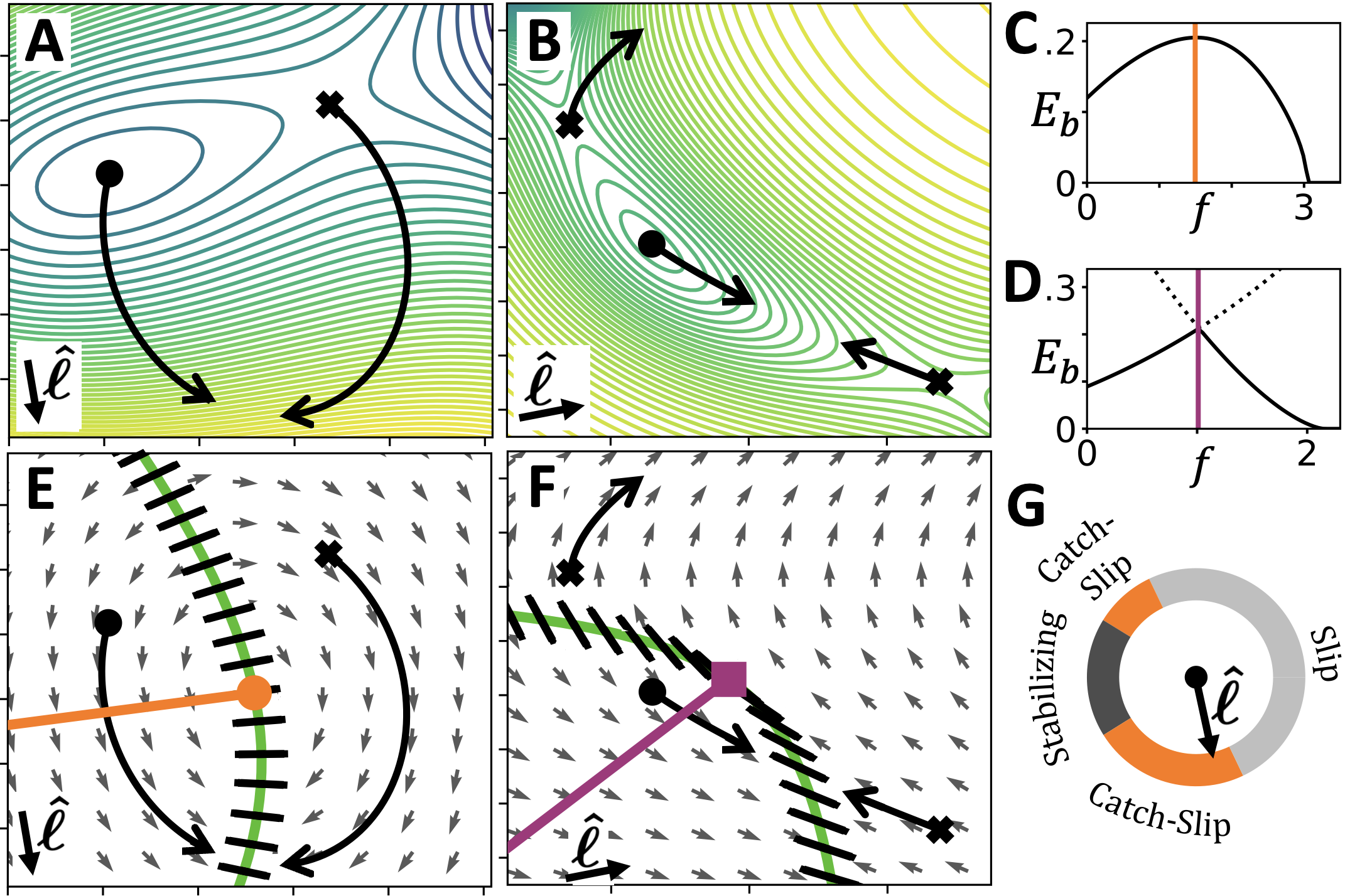
Switch points — The flow described by Eq. 2 can have singularities that generate a force-induced switch. To see this, first note that Eq. 2 is undefined on the curve where , where is the -dependent Hessian. This curve separates regions of configuration space with minimum-like curvature from regions with saddle-like curvature, from regions with maximum-like curvature. The curve behaves as either a source or a sink under the flow. Fig. 1E and F show the flow vector field and curve (green) corresponding to Fig. 1A and B, respectively. As shown, the flow points either outward away from the curve (source) or inward towards it (sink). Hence, solutions of Eq. 2 (i.e. integral curves of the flow) emerge from and/or coalesce with the curve. As a consequence, global behavior of Eq. 2 is revealed by examining local behavior near the curve. This local behavior is described by the equation (see SM)
| (3) |
Here, is the eigenvalue of that passes through zero along the curve, and is the corresponding eigenvector. Importantly, and (which are functions of position along the curve) are independent of applied force, as is the curve itself. Eq. 3 implies that flow vectors along the curve point outward or inward parallel to . Letting denote an outward-pointing unit vector normal to the curve, the flow vectors point outward if , or equivalently, . They point inward if . We define a switch point as a singular point at which the quantity passes through zero. In other words, switch points are where the flow switches from outward (source) to inward (sink). Switch points come in two varieties: -switch points, where , and -switch points, where . As suggested from the examples in Fig. 1, -switch points signify a catch-slip (or slip-catch) switch via a single pathway, and -switch points signify a switch between pathways. In the SM we discuss the geometric basis for these behaviors of - and - switch points. To identify the location of switch points, one can simply plot the vectors along the curve. These are shown as black hash marks in Fig. 1D and F. Note that the sign of is immaterial, so the hash marks have no arrow to indicate a sign. -switch points are located where a hash mark is perpendicular to (i.e. ), and -switch points are located where a hash mark is tangent to the curve (i.e. ). The switch points in Fig. 1E and F are shown as an orange dot and purple square, respectively.
Emanating from a switch point is a switch line (orange and purple lines in Fig. 1E and F, respectively) which marks where the switch occurs. Specifically, the switch in behavior occurs when the minimum crosses the switch line under increasing . A switch line emanating from an -switch point indicates catch-slip or slip-catch via a single pathway: when the minimum is on the switch line. A switch line emanating from an -switch point indicates a switch in pathway, i.e. the lowest-energy saddle switches from one saddle to another as the minimum crosses the switch line. For a minimum on this type of switch line, the energy barriers of two saddles are equal. Switch lines partition configuration space into regions of a given behavior. For instance, in Fig. 1E, the minimum begins in a ‘catch region’ and is pulled across the switch line into a ‘slip region’ as increases. To third order in , switch lines are straight lines, and equations for their direction are given in the SM.
The framework of switch points and switch lines reveals behaviors that would otherwise be ‘invisible’ from viewing the free energy landscape at any particular force. Three examples are:
(i) Consider modifying the force direction in Fig. 1A and E. Varying moves the -switch point along the curve, modifying the force at which the switch from catch to slip occurs. Fig. 1G shows the behavior for any given direction . Slip behavior occurs for a wide range of directions that are roughly aligned with the reaction pathway of bond rupture (i.e the direct path from minimum to saddle). For force directions opposite to the reaction pathway, the force stabilizes the bond, acting as a “pushing” force rather than a “pulling” force. Between the slip regime and stabilizing regime are catch-slip regimes. As indicated, the in Fig. 1A and E falls into the catch-slip regime.
(ii) Consider that the bond may be under stress due to its local environment, resulting in an additional force on the bond which moves the initial condition of Eq. 2 to points satisfying . The force can move the initial position of the minimum across a switch line, from a catch region to a slip region, or vice versa. This phenomenon may be at play in two-site ‘dynamic catch’ bonds Fiore et al. (2014); Zhu et al. (2019), where a ligand with two binding sites exhibits slip behavior when bound to either site individually, but catch-slip behavior when both sites are bound. We analyze a toy model of such a scenario in the SM. Briefly summarized, if the ligand is bound at just one site, the minimum is in a slip region. When the ligand binds at the second site, the minimum is pulled into the catch region, so that the system exhibits catch-slip behavior only when both sites are bound.
(iii) Whether or not a pathway switch may occur cannot be inferred simply from the existence or absence of multiple saddle points because pathways can be created or destroyed as varies Konda et al. (2014). However, the existence (or absence) of an -switch point is a definitive indication of the possibility (or impossibility) of a pathway switch.
The framework of switch points also lets us address the question: how prevalent are free energy landscapes that exhibit catch-slip behavior? Remarkably, the answer is that almost every 2-dimensional will exhibit catch-slip behavior for an appropriate and . Indeed, there exists an that generates an -switch point for all but a measure-zero subset of smooth functions (the only requirement for the existence of such an is that not all be parallel along the curve separating minimum-like and saddle-like regions). Given these observations, we suggest that investigating pulling directions and internal stresses, rather than investigating complex bonding mechanisms, may be the key to understanding much of the catch-slip behavior observed in biological systems.
Application to P-Selectin — To illustrate the utility of the geometric framework of switch points and switch lines, we develop a model of the catch-slip bond between P-Selectin and its glycoprotein ligand-1 (PSGL-1). This catch-slip behavior is believed to mediate leukocyte ‘rolling’ McEver and Zhu (2010). We propose a 2-dimensional free energy landscape for this bond based on structural considerations and we find close agreement with experimental data Marshall et al. (2003) with just with 3 fit parameters (see SM). Fig. 2A shows the structure of P-Selectin (teal) and PSGL-1 (magenta) and the two degrees of freedom: angle between two domains and distance between protein and ligand.
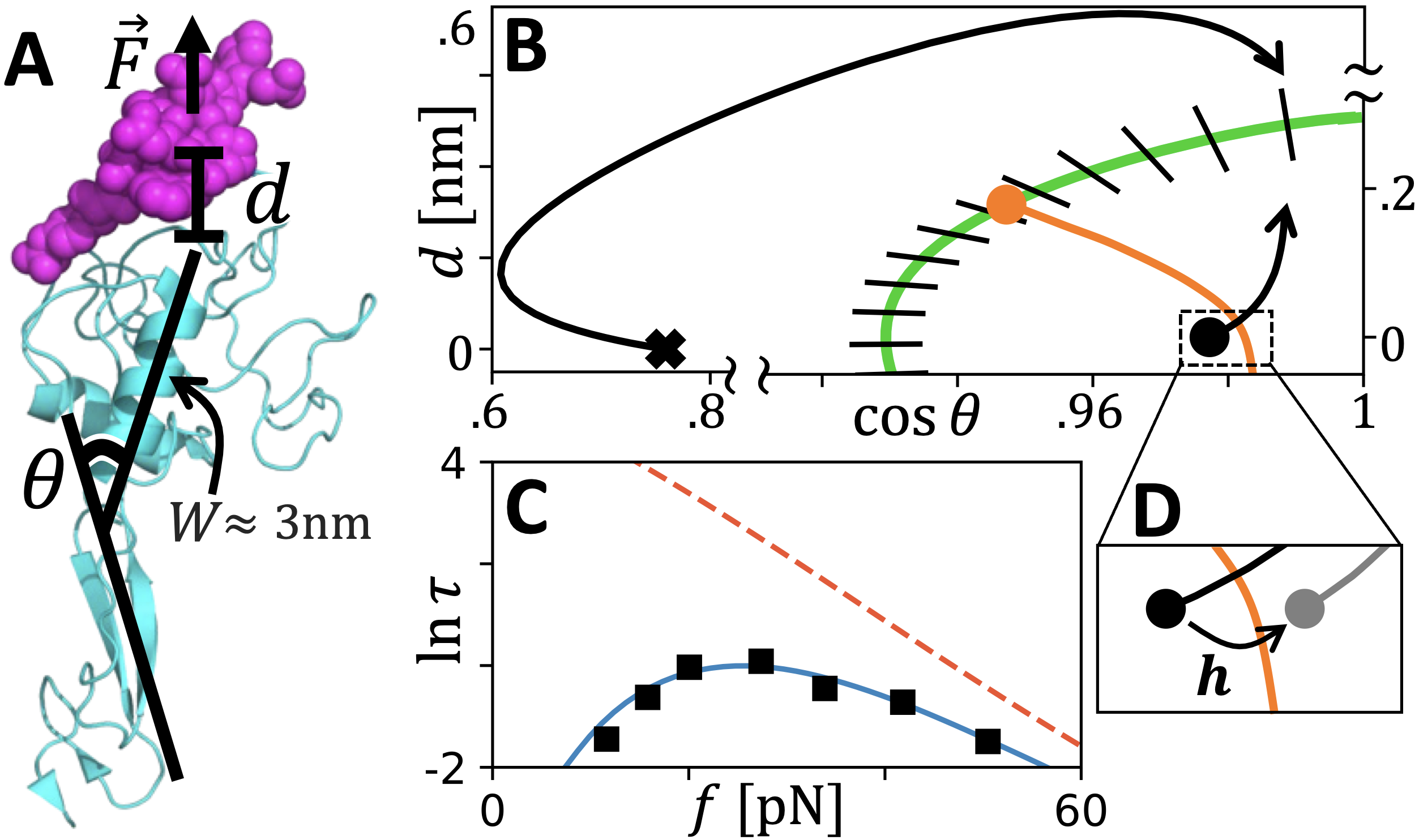
The geometric framework (Fig. 2B) reveals one -switch point (orange dot) and no -switch points—this is topologically equivalent to the example in Fig. 1E. The absence of an -switch point indicates that a pathway switch cannot occur in this model at any force, regardless of mangitude or direction (recall that the absence of two saddles at any particular force is insufficient to make this strong claim). Under increasing force, the minimum is pulled across the switch line (Fig. 2B orange curve), generating catch-slip behavior with force-dependent bond lifetime in close agreement with experimental data Marshall et al. (2003) (Fig. 2C; experiment: black squares; model: solid blue curve). Our model predicts that an additional force pushing upward on the lectin domain will move the minimum across the switch line (Fig. 2D), erasing the catch behavior as well as strengthening the bond at zero force (Fig. 2C dashed orange curve shows the predicted ). In the SM we discuss this prediction in more detail and speculate that this response may put an evolutionary constraint on the length of the consensus repeats McEver and Zhu (2010) that attach the lectin domain to the membrane.
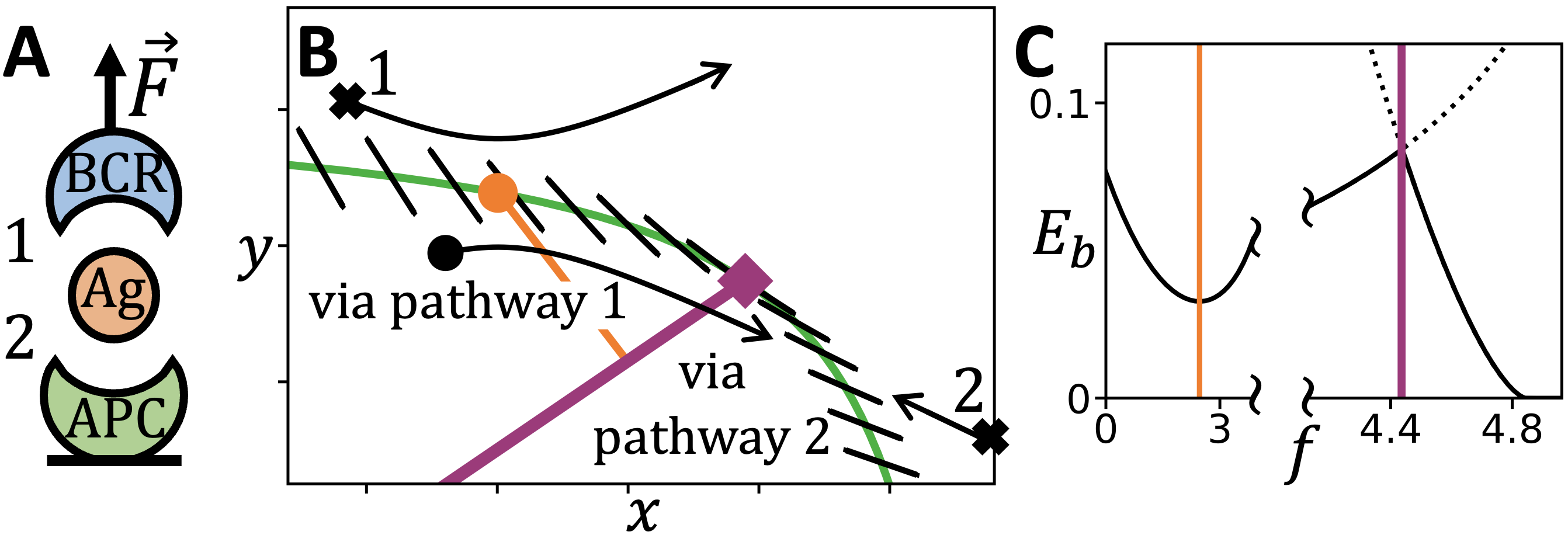
Interplay of - and -switch points — - and -switch points can appear in the same bond, generating catch-slip and pathway switching at different forces. As an example, we generalize a recently-proposed model for the “tug-of-war” process of antigen (Ag) extraction by B-cell receptors (BCR) Jiang and Wang (2022a, b). Fig. 3A shows a schematic of this system: a BCR (blue) and antigen-presenting cell receptor (APC, green) pull on either end of an Ag fragment (orange) until rupture occurs either by pathway 1 or 2 (as labelled). A force-induced switch in this rupture pathway is believed to signal antigen affinity. While the original model treats the BCR-Ag and APC-Ag bonds as independent Jiang and Wang (2022a), coupling between these bonds (which could arise, for example, from allistory of the antigen) generates a richer geometric picture (Fig. 3B). An -switch point (purple square) and associated switch line indicates where the pathway switch occurs. Additionally, an -switch point (orange dot) exists due to the force direction imposed by the geometry (see SM). This results in slip-catch behavior via pathway 1 at low forces, so that the BCR-Ag bond is strong at zero force, easily dissociates at intermediate force, then strengthens at higher force so that rupture via the APC-Ag bond becomes favorable. The energy barrier vs. is shown in Fig. 3C. The slip-catch switch at low force and pathway switch at high force are marked by orange and purple bars, respectively. Such slip-catch-slip, or triphasic behavior has been observed in selectins Chakrabarti et al. (2017), and in the SM we further discuss the plausibility of this behavior in antigen extraction.
In more complex bonds, many - and -switch points can appear together. In the SM we analyze a model of the sliding-rebinding catch-bond mechanism Lou and Zhu (2007). This model contains four switch points in total, and our geometric framework organizes this complex scenario into an intuitive picture. Note that in 2 dimensions, - and -switch point are the only singularities that can occur in the flow along the curve, so combinations of - and -switch points cover all possible switching behaviors in 2 dimensional models. In higher dimensions, switch points can be generalized, and we show in the SM that this generalization reveals more exotic responses to applied force, in addition to catch-slip and pathway switching.
Discussion — We present a geometric framework for characterizing force-induced switching behavior in 2-dimensional free energy landscapes. We find geometric signatures—switch points and switch lines—that identify both catch-slip switches via a single pathway and switching between pathways. Using this framework, we show that almost every 2-dimensional free energy landscape will exhibit catch-slip behaviour under an appropriate force. Indeed, very simple bonds show catch behavior when pulled in the right direction and/or put under certain stresses. This motivates experiments that probe multiple pulling directions (as in Gittes et al. (1996); Nicholas et al. (2015); Jagannathan et al. (2012); Huang et al. (2017)) and investigations into the orientation of bonds in their native context. Additionally, the ubiquity of catch-slip behavior suggests simple bonds may serve as evolutionary stepping-stones in the evolution of specialized catch bond mechanisms. In the SM, we analyze established catch-bond models and identify the signatures of their switching behavior.
Higher-dimensional generalizations of switch points will enlarge the applicability of this framework. In the SM, we show that such generalized switch points signify more exotic responses to force, in addition to catch-slip and pathway switches. Future work is needed to explore the range of possible behaviors. An assumption of our approach is that the force dependence of bond lifetime is determined predominantly by the force-dependence of the energy barrier . While this is typically well justified Avdoshenko and Makarov (2016), it was recently suggested experimentally that force-dependent entropic effects (captured by Langer’s prefactor ) can be important Farago et al. (2021), motivating theoretical investigation into this possibility.
Acknowledgements.
We thank our late friend and colleague Alex Levine for suggesting this project and Shenshen Wang for introducing us to the importance of catch bonding and pathway switching in the context of receptor-antigen interactions and also for providing us with important references. C.B. also thanks Jonathon Howard for stimulating discussions and references. C.B. is grateful for support from the NSF Graduate Research Fellowship Program (NSF Grant No. DGE-2034835) and R.B. would like to thank the NSF-DMR for continued support under CMMT Grant No.1836404.References
- Stirnemann (2022) G. Stirnemann, The Journal of Physical Chemistry B 126, 1365 (2022).
- Sokurenko et al. (2008) E. V. Sokurenko, V. Vogel, and W. E. Thomas, Cell host & microbe 4, 314 (2008).
- McEver (2015) R. P. McEver, Cardiovascular research 107, 331 (2015).
- Chakrabarti et al. (2017) S. Chakrabarti, M. Hinczewski, and D. Thirumalai, Journal of structural biology 197, 50 (2017).
- Zhu et al. (2019) C. Zhu, Y. Chen, and L. A. Ju, Current opinion in chemical biology 53, 88 (2019).
- Guo and Guilford (2006) B. Guo and W. H. Guilford, Proceedings of the National Academy of Sciences 103, 9844 (2006).
- Leidel et al. (2012) C. Leidel, R. A. Longoria, F. M. Gutierrez, and G. T. Shubeita, Biophysical journal 103, 492 (2012).
- Rai et al. (2013) A. K. Rai, A. Rai, A. J. Ramaiya, R. Jha, and R. Mallik, Cell 152, 172 (2013).
- Nord et al. (2017) A. L. Nord, E. Gachon, R. Perez-Carrasco, J. A. Nirody, A. Barducci, R. M. Berry, and F. Pedaci, Proceedings of the National Academy of Sciences 114, 12952 (2017).
- Brockman and Salaita (2019) J. M. Brockman and K. Salaita, Frontiers in physics 7, 14 (2019).
- Choi et al. (2022) H.-K. Choi, K. Li, M. N. Rushdi, C. Ge, W. Chen, J. Lou, and C. Zhu, bioRxiv (2022).
- Knežević et al. (2018) M. Knežević, H. Jiang, and S. Wang, Physical review letters 121, 238101 (2018).
- Jiang and Wang (2022a) H. Jiang and S. Wang, arXiv preprint arXiv:2209.13991 (2022a).
- Jiang and Wang (2022b) H. Jiang and S. Wang, arXiv preprint arXiv:2209.13994 (2022b).
- Wu et al. (2019) P. Wu, T. Zhang, B. Liu, P. Fei, L. Cui, R. Qin, H. Zhu, D. Yao, R. J. Martinez, W. Hu, et al., Molecular cell 73, 1015 (2019).
- Spillane and Tolar (2018) K. M. Spillane and P. Tolar, Molecular immunology 101, 319 (2018).
- Wang (2021) S. Wang, BioEssays 43, 2100045 (2021).
- Graham and Best (2011) T. G. Graham and R. B. Best, The Journal of Physical Chemistry B 115, 1546 (2011).
- Guinn et al. (2015) E. J. Guinn, B. Jagannathan, and S. Marqusee, Nature communications 6, 1 (2015).
- Wales and Head-Gordon (2012) D. J. Wales and T. Head-Gordon, The Journal of Physical Chemistry B 116, 8394 (2012).
- Pierse and Dudko (2017) C. A. Pierse and O. K. Dudko, Physical review letters 118, 088101 (2017).
- Jagannathan et al. (2012) B. Jagannathan, P. J. Elms, C. Bustamante, and S. Marqusee, Proceedings of the National Academy of Sciences 109, 17820 (2012).
- Makarov (2016) D. E. Makarov, The Journal of chemical physics 144, 030901 (2016).
- Zhuravlev et al. (2016) P. I. Zhuravlev, M. Hinczewski, S. Chakrabarti, S. Marqusee, and D. Thirumalai, Proceedings of the National Academy of Sciences 113, E715 (2016).
- Suzuki and Dudko (2011) Y. Suzuki and O. K. Dudko, The Journal of chemical physics 134, 065102 (2011).
- Bartolo et al. (2002) D. Bartolo, I. Derényi, and A. Ajdari, Physical Review E 65, 051910 (2002).
- Evans et al. (2004) E. Evans, A. Leung, V. Heinrich, and C. Zhu, Proceedings of the National Academy of Sciences 101, 11281 (2004).
- Pereverzev et al. (2005) Y. V. Pereverzev, O. V. Prezhdo, M. Forero, E. V. Sokurenko, and W. E. Thomas, Biophysical journal 89, 1446 (2005).
- Barsegov and Thirumalai (2005) V. Barsegov and D. Thirumalai, Proceedings of the National Academy of Sciences 102, 1835 (2005).
- Lou and Zhu (2007) J. Lou and C. Zhu, Biophysical journal 92, 1471 (2007).
- Suzuki and Dudko (2010) Y. Suzuki and O. K. Dudko, Physical review letters 104, 048101 (2010).
- Konda et al. (2013) S. S. M. Konda, J. N. Brantley, B. T. Varghese, K. M. Wiggins, C. W. Bielawski, and D. E. Makarov, Journal of the American Chemical Society 135, 12722 (2013).
- Quapp and Bofill (2016) W. Quapp and J. M. Bofill, Journal of computational chemistry 37, 2467 (2016).
- Chakrabarti et al. (2014) S. Chakrabarti, M. Hinczewski, and D. Thirumalai, Proceedings of the National Academy of Sciences 111, 9048 (2014).
- Adhikari et al. (2018) S. Adhikari, J. Moran, C. Weddle, and M. Hinczewski, PLoS computational biology 14, e1006399 (2018).
- Kong et al. (2013) F. Kong, Z. Li, W. M. Parks, D. W. Dumbauld, A. J. García, A. P. Mould, M. J. Humphries, and C. Zhu, Molecular cell 49, 1060 (2013).
- Chen et al. (2015) X. Chen, Z. Mao, and B. Chen, Scientific reports 5, 1 (2015).
- Li et al. (2016) Z. Li, F. Kong, and C. Zhu, Scientific reports 6, 1 (2016).
- Langer (1969) J. S. Langer, Annals of Physics 54, 258 (1969).
- Avdoshenko and Makarov (2016) S. M. Avdoshenko and D. E. Makarov, The Journal of Physical Chemistry B 120, 1537 (2016).
- Quapp et al. (2018) W. Quapp, J. M. Bofill, and J. Ribas-Ariño, International Journal of Quantum Chemistry 118, e25775 (2018).
- Konda et al. (2014) S. S. M. Konda, S. M. Avdoshenko, and D. E. Makarov, The Journal of chemical physics 140, 104114 (2014).
- Evans and Ritchie (1997) E. Evans and K. Ritchie, Biophysical journal 72, 1541 (1997).
- Dudko et al. (2006) O. K. Dudko, G. Hummer, and A. Szabo, Physical review letters 96, 108101 (2006).
- Fiore et al. (2014) V. F. Fiore, L. Ju, Y. Chen, C. Zhu, and T. H. Barker, Nature communications 5, 1 (2014).
- McEver and Zhu (2010) R. P. McEver and C. Zhu, Annual review of cell and developmental biology 26, 363 (2010).
- Marshall et al. (2003) B. T. Marshall, M. Long, J. W. Piper, T. Yago, R. P. McEver, and C. Zhu, Nature 423, 190 (2003).
- Somers et al. (2000) W. S. Somers, J. Tang, G. D. Shaw, and R. T. Camphausen, Cell 103, 467 (2000).
- Gittes et al. (1996) F. Gittes, E. Meyhöfer, S. Baek, and J. Howard, Biophysical journal 70, 418 (1996).
- Nicholas et al. (2015) M. P. Nicholas, F. Berger, L. Rao, S. Brenner, C. Cho, and A. Gennerich, Proceedings of the National Academy of Sciences 112, 6371 (2015).
- Huang et al. (2017) D. L. Huang, N. A. Bax, C. D. Buckley, W. I. Weis, and A. R. Dunn, Science 357, 703 (2017).
- Farago et al. (2021) B. Farago, I. D. Nicholl, S. Wang, X. Cheng, D. J. Callaway, and Z. Bu, Proceedings of the National Academy of Sciences 118, e2025012118 (2021).