Space-time wave packets propagating a kilometer in air
Abstract
We report on the diffraction-free propagation of space-time wave packets (STWPs) – a class of propagation-invariant pulsed beams – for km in an open-air laser range in a low-turbulence scenario. Making use of -fs pulses (bandwidth nm) at a wavelength of m, we construct an STWP with a transverse width of mm that expands to mm after m, and another that expands from mm to mm after 1 km. The propagation of the STWPs is compared to Gaussian wave packets of the same transverse spatial width and bandwidth. We establish a theoretical model that accounts for the significant factors limiting the STWP propagation distance and suggests the path to further extending this distance.
Since the introduction of the Bessel beam in 1987 [1], the potential utility of so-called ‘diffraction-free’ monochromatic beams [2, 3] in long-distance propagation has been of continued interest, with potential applications in free-space communications. The experimental tests carried out to date demonstrated propagation distances typically on the order of meters [4, 5, 6, 7]. Exceptions include 1-km experiments making use of a Bessel-like beam with controlled wavefront spherical aberrations [8], and most recently using an auto-focusing beam (a circularly symmetric Airy beam at a wavelength of 532 nm) whose initial 6-mm-diameter peak extends to 9 mm after 1 km [9].
We have recently investigated a family of propagation-invariant (diffraction-free and dispersion-free) pulsed beams dubbed ‘space-time wave packets’ (STWPs) [10, 11]. STWPs are endowed with angular dispersion [12]; i.e., each wavelength travels at a prescribed angle with respect to the propagation axis. In contrast, conventional tilted pulse fronts [13] that are also endowed with angular dispersion (AD) are not propagation invariant. We have recently uncovered that the AD undergirding STWPs is ‘non-differentiable’; i.e., the derivative of the propagation angle with respect to wavelength is not defined at a particular wavelength [14, 15, 16]. The non-differentiability of the underlying AD profile is the key to the unique attributes of STWPs, rendering them distinct from tilted pulse fronts. Besides propagation invariance, STWPs have tunable on-axis group velocity [17, 18, 19, 20] and group-velocity dispersion [21], and exhibit self-healing [22] and anomalous refraction phenomena [23].
Initial demonstrations of STWPs verified propagation invariance over small distances, which are nevertheless significantly larger than the Rayleigh range of a Gaussian beam having the same initial spatial width. We have increased the propagation distance of STWPs from mm in [10], to m in a laboratory environment [24], and m after directing the beam out of the laboratory and down a service chase in our research building [25]. Our previous work predicted theoretically the possibility of extending to the kilometer range.
Here we report on propagation measurements for STWPs over km in the open environment of a laser range in Florida (TISTEF: Townes Institute Science and Technology Experimentation Facility). We first establish a theoretical model that accounts for the various factors that limit the propagation distance of an STWP. Based on this model we synthesize STWPs at a wavelength nm and bandwidth nm. The transverse width of one STWP expands from mm to mm after 500 m; a Gaussian wave packet expands over the same distance to mm (Rayleigh range m). The width of another STWP expands from mm to mm after 1 km; a corresponding Gaussian wave packet expands to mm ( m). Our model points to the improvements required to extend to the 10-km range and beyond, which appears to be within current capabilities.
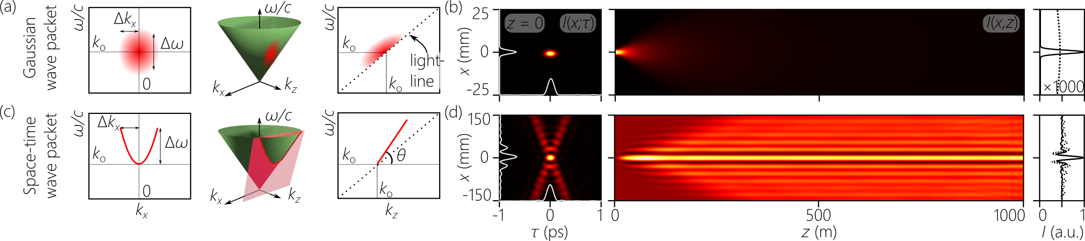
We compare conventional Gaussian wave packets (pulsed beams) in which the spatial and temporal degrees of freedom are separable, and STWPs in which they are not. We write the field in terms of a carrier and slowly varying envelope, , where is a carrier frequency, , and is the speed of light in vacuum. We make use here of only one transverse spatial dimension and hold the field uniform along . Recent developments have led to synthesizing STWPs modulated in both and [26, 27, 28], and we will make use of them for long-distance experiments in the near future. The envelope of the Gaussian wave packet is:
| (1) |
where and are the transverse and axial wave numbers, respectively, , and the spatio-temporal spectrum is the 2D Fourier transform of . The spectral support of such a wave packet is a 2D domain on the surface of the light-cone associated with the free-space dispersion relationship , and the spectral projections onto the and are also 2D domains [Fig. 1(a)]. The spatio-temporal spectrum of conventional wave packets is typically separable , which is manifest in the initial spatio-temporal intensity profile [Fig. 1(b)]. In the narrowband, paraxial regime we have , which leads to dephasing of the spatial frequencies along , and thus diffraction of the time-averaged intensity [Fig. 1(b)].
In contrast, the spatio-temporal spectrum of STWPs is not separable, and ideally a one-to-one relationship between and is enforced such that , and thus , which is equivalent to restricting the spectral support on the light-cone to a 1D trajectory at its intersection with a plane making an angle (the spectral tilt angle) with the -axis [Fig. 1(c)]. The STWP envelope takes the form:
| (2) |
which travels rigidly in free space at a group velocity [20]. The spatio-temporal intensity profile is X-shaped in any axial plane in this ideal limit [Fig. 1(d)].
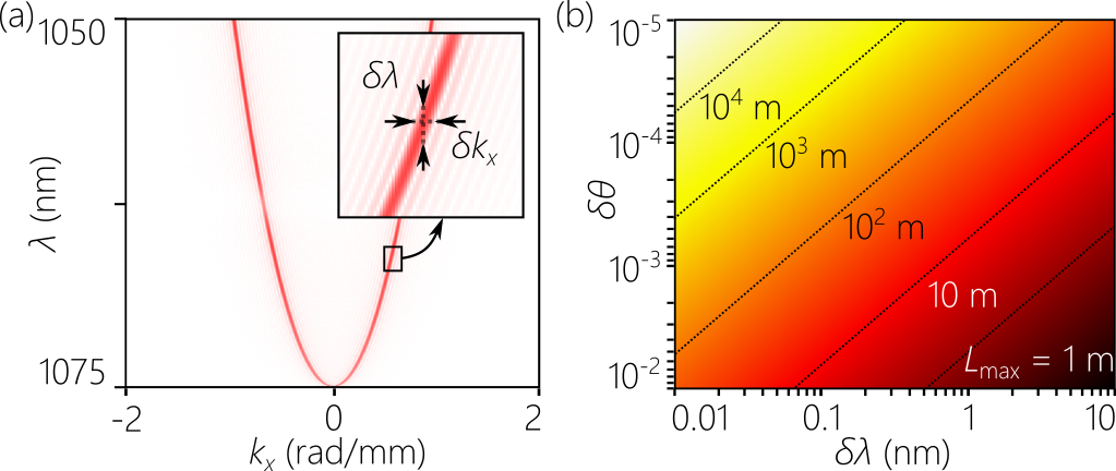
However, the ideal delta-function correlation between and [Fig. 1(c)] cannot be attained in practice because it implies an infinite energy. Instead, a finite spectral uncertainty arises in the association between and [Fig. 2(a)], in which case , where is a narrow function of width , and is the spatial frequency associated with in the ideal limit (in absence of spectral uncertainty). The spatial uncertainty is associated with a spectral uncertainty via [Fig. 2(a)]. Thus, rather than a mathematical parabola, the spatio-temporal spectrum projected onto the -plane has a finite ‘thickness’: eack spatial frequency is associated with a finite temporal bandwidth . This spectral uncertainty is one of the two key parameters that determines the propagation distance for an STWP, the other being : [29]. To increase one must reduce and have ; corresponds to a plane-wave pulse [30]. Defining an offset in the spectral tilt angle , we have for small and [25]; see Fig. 2(b).
To reach large values of , we must first identify the experimental factors that limit and . The experimental arrangement we use [31] is depicted in Fig. 3(a). We utilize pulses from a mode-locked laser (Spark Laser, Alcor) of width fs, bandwidth nm, central wavelength m, and average power W. The initial -mm beam width is magnified with a beam expander and directed to a diffraction grating (1200 lines/mm, mm2). The -1 diffraction order is collimated by a cylindrical lens (focal length mm), and the spatially resolved spectrum traverses a transparent phase plate that modulates the spatial phase to associate a prescribed pair of symmetric spatial frequencies to each wavelength , before the pulse is reconstituted by an identical grating-lens pair. The phase plate is fabricated via gray-scale lithography using the procedure outlined in [32]. The phase plate also acts as a limiting aperture in the system of width (here mm).

In considering the limit on , it is important to note that is not an angle in physical space, but is an angular parameter that determines the rate of change of across the bandwidth . The spatio-temporal spectrum is captured by placing a mirror after the second cylindrical lens to deflect the field beam before the second grating, and focus the spatio-temporal spectrum using a spherical lens in a configuration to a CCD camera. The measurements in Fig. 3(b) indicate that can be made very small. The results in as shown in Fig. 3(b) correspond to , , and (all in degrees); the latter two of which are utilized in our long-distance experiments. Therefore, the span of values of in Fig. 2(b) is currently accessible.
With regards to the second factor limiting , the spectral uncertainty , we previously identified the spectral resolution of the grating , where is the grating groove density and is its width, as the main contributor, [29, 33]. In Fig. 3(c) we plot the measured while varying the width of the grating aperture [Fig. 3(a)]. We measure at the focal plane where the phase plate is placed by capturing the field with a single mode fiber coupled to an optical spectrum analyzer (Advantest AQ6317B), and the measurements plotted in Fig. 3(c) confirm the expected dependence. Crucially, the contribution of to is independent of .
The measurements shown in Fig. 3(c) indicate that the small values of needed to reach the km-range according to Fig. 2(b) are accessible. However, in the course of our experiments we have identified a second factor contributing to : the height of the phase plate [Fig. 3(a)], which represents a limiting spatial aperture for the synthesis system. This aperture results in a new contribution to the spectral uncertainty we denote . it can be shown that , and the total spectral uncertainty is , which is exact if the spectral uncertainties are modelled with Gaussian spectral profiles. Because depends on , it must be measured after the phase plate. We carry out a spatial Fourier transform of the STWP along after the second cylindrical lens, and a single-mode fiber coupled to the optical spectrum analyzer captures the spectral width . From these results, it is clear that needs to be enlarged to reach the kilometer scale.

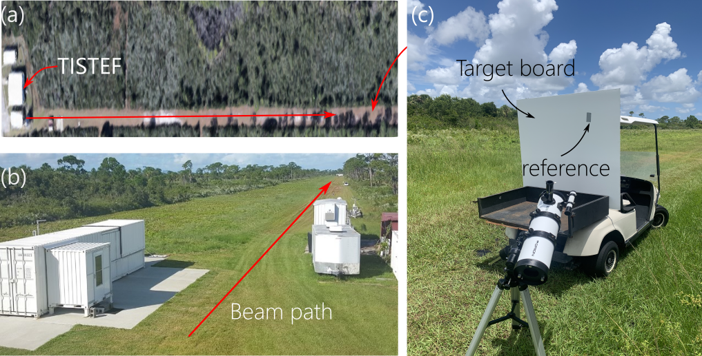
The TISTEF laser range facility in which we carried out our experiments is shown in Fig. 4, which comprises a 1-km terrestrial laser range in the vicinity of NASA’s Kennedy space center. Crucially for our measurements, TISTEF is capable of providing real-time atmospheric turbulence measurements. The transverse width of the STWP produced by the setup in Fig. 3(a) is enlarged from mm to mm using a combination of a negative lens ( mm, 50-mm diameter) and a positive lens ( mm, 150-mm diameter), which provide a magnification and minimize the spherical aberrations to 1.2 wavelengths. The divergence in this system is mrad, whereas the ideal divergence is mrad as determined by Zemax calculations. The STWP is then launched from the laboratory through an open window onto the laser-range grass field [Fig. 4(a)]. To detect the beam, we intercept it with a painted metal board on the back of a vehicle that moves to targeted distances down the range to km from the laboratory. To locate the STWP as the vehicle moves down the range, we image the STWP on the board via a telescope to a CCD (equipped with a 20-nm-bandwidth spectral filter centered at 1064 nm) placed in the laboratory next to the synthesis setup [Fig. 4(a)]. A second image is taken in situ down the range next to the board with a smaller telescope to a similar CCD and spectral filter [Fig. 4(b)]. In addition to the STWPs, we also launch down the range Gaussian wave packets with separable spatial and temporal degrees of freedom for comparison. These Gaussian wave packets are taken from the laser directly [Fig. 3(a)], so they have the same bandwidth as the STWPs, and their transverse width is made to match for the STWPs.
The measurements taken down the laser range are plotted in Fig. 5 for beams of width mm [Fig. 5(a)] and mm [Fig. 5(b)]. In each case, we plot the measured along for an STWP and a reference Gaussian wave packet of equal initial width at . It is clear in both cases that the width of the Gaussian wave packet increases rapidly with , whereas that for the STWP is maintained for a significantly extended distance. In Fig. 5(a), the width for the STWP increases from mm to mm at 500 m, whereas the width of the corresponding Gaussian wave packet increases to mm at 200 mm (sunlight prevented measurements at longer distances). Extending the propagation distance of the Gaussian wave packet to 500 m, its width is that of the STWP. In Fig. 5(b), the width for the STWP increases from mm to mm at 1 km, whereas that for the corresponding Gaussian wave packet increases to mm at 200 mm. At 1 km, the width of the Gaussian wave packet is that of the STWP.
These results were obtained in the early morning with measured refractive-index structure parameter m-2/3; as such, the impact of turbulence was minimal. We have carried out measurements corresponding to m-2/3, and have found that the root-mean-square error of the STWPs is consistently lower than those of the Gaussian wave packets. Future measurements will aim at achieving longer according to the predictions in Fig. 2(b) by further reducing (by increasing the aperture ). Moreover, we will make use of STWPs that are localized in both transverse dimensions [28]. The transverse intensity profile in this case is circularly symmetric with a radial decay rate ( is the radial coordinate) and no pedestal. Finally, note that the wavelength used here is m compared to m in [9], and thus the 1-km propagation distance recorded here is equivalent to twice that in [9].
In conclusion, we have demonstrated kilometer-scale propagation of STWPs in air and compared their diffractive spreading to that of Gaussian wave packets having the same spatial and temporal bandwidths as the STWPs. We observe minimal increase in the STWP transverse width with respect to that of the Gaussian wave packets. Our theoretical model for the propagation distance as determined by the experimental parameters indicates that longer distances ( km) are within reach.
Funding
U.S. Office of Naval Research (ONR) N00014-19-1-2192.
Acknowledgments
We thank the TISTEF staff for assistance.
Disclosures
The authors declare no conflicts of interest.
Data availability
Data underlying the results presented in this paper are not publicly available at this time but may be obtained from the authors upon reasonable request.
References
- Durnin et al. [1987] J. Durnin, J. J. Miceli, and J. H. Eberly, Diffraction-free beams, Phys. Rev. Lett. 58, 1499 (1987).
- McGloin and Dholakia [2005] D. McGloin and K. Dholakia, Bessel beams: diffraction in a new light, Contemp. Phys. 46, 15 (2005).
- Turunen and Friberg [2010] J. Turunen and A. T. Friberg, Propagation-invariant optical fields, Prog. Opt. 54, 1 (2010).
- Turunen et al. [1988] J. Turunen, A. Vasara, and A. T. Friberg, Holographic generation of diffraction-free beams, Appl. Opt. 27, 3959 (1988).
- Cox and Dibble [1992] A. J. Cox and D. C. Dibble, Constant-axial-intensity nondiffracting beam, J. Opt. Soc. Am. A 9, 282 (1992).
- Vetter et al. [2019] C. Vetter, R. Steinkopf, K. Bergner, M. Ornigotti, S. Nolte, H. Gross, and A. Szameit, Realization of free-space long-distance self-healing Bessel beams, Laser Photon. Rev. 13, 1900103 (2019).
- L.Stoyanov et al. [2021] L.Stoyanov, Y. Zhang, A. Dreischuh, and G. P. Paulus, Long-range quasi-non-diffracting Gauss-Bessel beams in a few-cycle laser field, Opt. Express 29, 10997 (2021).
- Aruga et al. [1999] T. Aruga, S. W. Li, S. Yoshikado, M. Takabe, and R. Li, Nondiffracting narrow light beam with small atmospheric turbulence-influenced propagation, Appl. Opt. 38, 3152 (1999).
- Zhang et al. [2019] Z. Zhang, X. Liang, M. Goutsoulas, D. Li, X. Yang, S. Yin, J. Xu, D. N. Christodoulides, N. K. Efremidis, and Z. Chen, Robust propagation of pin-like optical beam through atmospheric turbulence, APL Photon. 4, 076103 (2019).
- Kondakci and Abouraddy [2017] H. E. Kondakci and A. F. Abouraddy, Diffraction-free space-time beams, Nat. Photon. 11, 733 (2017).
- Yessenov et al. [2022a] M. Yessenov, L. A. Hall, K. L. Schepler, and A. F. Abouraddy, Space-time wave packets, Adv. Opt. Photon. 14, 455 (2022a).
- Torres et al. [2010] J. P. Torres, M. Hendrych, and A. Valencia, Angular dispersion: an enabling tool in nonlinear and quantum optics, Adv. Opt. Photon. 2, 319 (2010).
- Fülöp and Hebling [2010] J. A. Fülöp and J. Hebling, Applications of tilted-pulse-front excitation, in Recent Optical and Photonic Technologies, edited by K. Y. Kim (InTech, 2010).
- Hall et al. [2021] L. A. Hall, M. Yessenov, and A. F. Abouraddy, Space-time wave packets violate the universal relationship between angular dispersion and pulse-front tilt, Opt. Lett. 46, 1672 (2021).
- Hall and Abouraddy [2021] L. A. Hall and A. F. Abouraddy, Realizing normal group-velocity dispersion in free space via angular dispersion, Opt. Lett. 46, 5421 (2021).
- Hall and Abouraddy [2022] L. A. Hall and A. F. Abouraddy, Consequences of non-differentiable angular dispersion in optics: Tilted pulse fronts versus space-time wave packets, Opt. Express 30, 4817 (2022).
- Salo and Salomaa [2001] J. Salo and M. M. Salomaa, Diffraction-free pulses at arbitrary speeds, J. Opt. A 3, 366 (2001).
- Efremidis [2017] N. K. Efremidis, Spatiotemporal diffraction-free pulsed beams in free-space of the Airy and Bessel type, Opt. Lett. 42, 5038 (2017).
- Wong and Kaminer [2017] L. J. Wong and I. Kaminer, Ultrashort tilted-pulsefront pulses and nonparaxial tilted-phase-front beams, ACS Photon. 4, 2257 (2017).
- Kondakci and Abouraddy [2019] H. E. Kondakci and A. F. Abouraddy, Optical space-time wave packets of arbitrary group velocity in free space, Nat. Commun. 10, 929 (2019).
- Yessenov et al. [2021] M. Yessenov, L. A. Hall, and A. F. Abouraddy, Engineering the optical vacuum: Arbitrary magnitude, sign, and order of dispersion in free space using space-time wave packets, arXiv:2102.09443 (2021).
- Kondakci and Abouraddy [2018] H. E. Kondakci and A. F. Abouraddy, Self-healing of space-time light sheets, Opt. Lett. 43, 3830 (2018).
- Bhaduri et al. [2020] B. Bhaduri, M. Yessenov, and A. F. Abouraddy, Anomalous refraction of optical spacetime wave packets, Nat. Photon. 14, 416 (2020).
- Bhaduri et al. [2018] B. Bhaduri, M. Yessenov, and A. F. Abouraddy, Meters-long propagation of diffraction-free space-time light sheets, Opt. Express 26, 20111 (2018).
- Bhaduri et al. [2019] B. Bhaduri, M. Yessenov, D. Reyes, J. Pena, M. Meem, S. R. Fairchild, R. Menon, M. C. Richardson, and A. F. Abouraddy, Broadband space-time wave packets propagating 70 m, Opt. Lett. 44, 2073 (2019).
- Guo et al. [2021] C. Guo, M. Xiao, M. Orenstein, and S. Fan, Structured 3D linear space-time light bullets by nonlocal nanophotonics, Light Sci. Appl. 10, 160 (2021).
- Pang et al. [2022] K. Pang, K. Zou, H. Song, M. Karpov, M. Yessenov, Z. Zhao, A. Minoofar, R. Zhang, H. Song, H. Zhou, X. Su, N. Hu, T. J. Kippenberg, A. F. Abouraddy, M. Tur, and A. E. Willner, Synthesis of near-diffraction-free orbital-angular-momentum space-time wave packets having a controllable group velocity using a frequency comb, Opt. Express 30, 16712 (2022).
- Yessenov et al. [2022b] M. Yessenov, J. Free, Z. Chen, E. G. Johnson, M. P. J. Lavery, M. A. Alonso, and A. F. Abouraddy, Space-time wave packets localized in all dimensions, Nat. Commun. 13, 4573 (2022b).
- Yessenov et al. [2019a] M. Yessenov, B. Bhaduri, L. Mach, D. Mardani, H. E. Kondakci, M. A. Alonso, G. A. Atia, and A. F. Abouraddy, What is the maximum differential group delay achievable by a space-time wave packet in free space?, Opt. Express 27, 12443 (2019a).
- Yessenov et al. [2019b] M. Yessenov, B. Bhaduri, H. E. Kondakci, and A. F. Abouraddy, Classification of propagation-invariant space-time light-sheets in free space: Theory and experiments, Phys. Rev. A 99, 023856 (2019b).
- Kondakci et al. [2018] H. E. Kondakci, M. Yessenov, M. Meem, D. Reyes, D. Thul, S. R. Fairchild, M. Richardson, R. Menon, and A. F. Abouraddy, Synthesizing broadband propagation-invariant space-time wave packets using transmissive phase plates, Opt. Express 26, 13628 (2018).
- Mohammad et al. [2017] N. Mohammad, M. Meem, X. Wan, and R. Menon, Full-color, large area, transmissive holograms enabled by multi-level diffractive optics, Sci. Rep. 7, 5789 (2017).
- Kondakci et al. [2019] H. E. Kondakci, M. A. Alonso, and A. F. Abouraddy, Classical entanglement underpins the propagation invariance of space-time wave packets, Opt. Lett. 44, 2645 (2019).