Soft Tiles: Capturing Physical Implementation Flexibility for Tightly-Coupled Parallel Processing Clusters
Abstract
Modern high-performance computing architectures (Multicore, GPU, Manycore) are based on tightly-coupled clusters of processing elements, physically implemented as rectangular tiles. Their size and aspect ratio strongly impact the achievable operating frequency and energy efficiency, but they should be as flexible as possible to achieve a high utilization for the top-level die floorplan. In this paper, we explore the flexibility range for a high-performance cluster of RISC-V cores with shared L1 memory used to build scalable accelerators, with the goal of establishing a hierarchical implementation methodology where clusters can be modeled as soft tiles to achieve optimal die utilization.
Index Terms:
Floorplanning, Soft Blocks, VLSI Architectures.I Introduction and Related Work
Floorplanning, the process of designing the physical layout of a chip, has a big impact on the performance, energy efficiency, time-to-market, and fabrication cost of VLSI chips. While the main objective of floorplanning has been chip area reduction—which directly translates into lowering production costs—the floorplanning process must also optimize wirelength, delays, thermal stability, and energy efficiency [1]. With the decreasing feature size of advanced nodes, the overall number of transistors per chip has skyrocketed. Higher transistor densities have enabled larger chip designs, directly increasing the turnaround time of naïve iterative floorplan refinement. To counteract this trend, researchers have explored new paradigms to accelerate the floorplanning process, leveraging Graphics Processing Units (GPUs) [2] and artificial intelligence [3].
Despite such advanced paradigms, the high cell counts of today’s high-performance chips make a hierarchical implementation flow a necessity. They can be tackled by following a top-down or a bottom-up approach. Top-down flows start by partitioning the die and allocating subregions of the chip layout to specific sub-blocks, generating constraints on their dimensions and aspect ratios. When implementing the sub-blocks, such requirements might be unfeasible or lead to sub-optimal quality of results (QoR), requiring lengthy iterations to converge to a feasible design. A bottom-up flow would start by fully implementing and hardening blocks at lower hierarchy levels before implementing the next hierarchy level based on these tiles. However, building upon hard tiles—which have fixed dimensions and even a fixed orientation in advanced technology nodes—might result in sub-optimal overall placement results, as they limit the possible top-level floorplans and make it more challenging to achieve a high utilization of the die area.
External Intellectual Property (IP) providers often deliver their modules as placed-and-routed hard tiles. However, for IPs owned by the chip designer, soft tiles are usually a better choice as their density and aspect ratios can be refined during placement. Additionally, introducing soft tiles enables a broader range of possible floorplans with higher overall utilization, especially when the die dimensions are fixed (fixed-outline floorplanning) and the designer needs to fulfill stringent requirements such as tight frequency and power constraints [4, 5]. Various works have investigated algorithms tackling the floorplanning challenges for designs with hard and soft tiles, e.g., Cull-and-Aggregate Bottom-Up Floorplanner (CABF) [1] or Iterative Merging Packing (IMP) [6]. However, the correlation between a soft tile’s physical shape (e.g., aspect ratio and macro placement) in floorplanning and its QoR after physical implementation has barely been analyzed so far.
Typically, modern architectures build upon a base compute cluster, combining multiple processing elements (PEs) sharing access to an L1 cache or Scratchpad Memory (SPM) via a low-latency interconnect. We call such a latency-critical cluster a tile. This tile is then replicated and interconnected with a latency-tolerant Network-on-Chip (NoC) to build a larger high-performance system. For example, considering multicore processors, Fujitsu’s A64FX [7] combines four interconnected Core Memory Groups (CGMs). Each CGM couples twelve compute (and one control) superscalar out-of-order vector-capable cores with a fast data cache. In addition, each CGM has a designated High Bandwidth Memory (HBM) controller enabling a bandwidth of to of HBM. As an example in the GPU field, NVIDIA’s A100 [8] architecture contains 108 Streaming Multiprocessors (SMs) grouped into Texture Processing Clusters, which in turn are grouped into GPU Processing Clusters. Each SM has a combined L1 data cache, a shared memory of , and four warps. Each warp includes a tensor core, 16 INT32 and FP32 cores, eight FP64 cores, and a large shared register file. Finally, Esperanto’s ET-SoC-1 [9], an exemplary manycore accelerator, couples more than one thousand energy-efficient RISC-V vector processors, each including a software-configurable L1 data cache or SPM, with four high-performance Linux-capable out-of-order Central Processing Units (CPUs). Esperanto uses a highly regular tiled architecture to fit all these cores on a chip. Eight energy-efficient RISC-V processors with a shared instruction cache (I$) form a neighborhood, and four neighborhoods with a L2 Static Random-Access Memory (SRAM) form a minion shire. Finally, 34 minion shires with of on-die memory and four Linux-capable CPUs form the full ET-SoC chip.
Finding an optimal floorplan with good post-place-and-route QoR for the tightly interconnected tile (multicore, GPU, manycore) is crucial for achieving high performance and efficiency of the overall design. The tile’s operating frequency ultimately determines the performance of the overall architecture. Moreover, the L1-to-PE latency is critical for high Instructions Per Cycle (IPC) and cannot easily be increased by pipelining to simplify implementation. In this scenario, the soft tile and system-level QoR need to be improved through physically-aware design approaches [10, 11].
This paper focuses on an open-source, high-performance cluster tile with eight compute (and one control) RISC-V cores connected to a shared L1 SPM through a low-latency interconnect [12]. Similarly to the state-of-the-art architectures, the cluster tile is then replicated to build a scaled-up high-performance acceleration system [13]. We explore the QoR of the physical implementation of this cluster as a soft tile based on a flexible range of aspect ratio and memory macro placement styles. The contributions of this paper are:
-
•
We propose three different memory macro placement styles for a cluster of RISC-V cores with a shared L1 SPM. For each, we place and route the cluster and evaluate its QoR in terms of achievable operating frequency, Total Negative Slack (TNS), number of violating paths, cell density, total routed wirelength (RtWL), and number of inserted buffers.
-
•
For all three proposed placement styles, we explore and evaluate the impact of the tile’s aspect ratio on the QoR.
-
•
Based on our results, we discuss a hierarchical implementation methodology where clusters can be modeled as soft tiles to achieve optimal overall die utilization.
II Architecture
The Snitch cluster [12] is an open-source RISC-V multicore cluster targeting highly-efficient double-precision floating-point computing. It is the compute unit of the Manticore architecture [13] where it is massively replicated.
II-A Cluster Tile
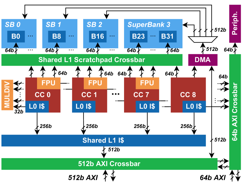
Figure 1 shows the architecture of the Snitch cluster configuration used in Manticore. It contains eight worker core complexes (CCs), each of which combines a small integer core, a trace L0 instruction cache, and a large double-precision Floating Point Unit (FPU) kept busy with custom architectural extensions. An additional ninth CC without an FPU controls a cluster-level Direct Memory Access (DMA) engine and can be used for cluster coordination. All CCs share a tightly-coupled L1 SPM divided into 32 memory banks, each wide, via a single-cycle SPM interconnect. Blocks of eight banks form superbanks, which are accessed in parallel by the DMA engine through a secondary wide interconnect. The CCs also share a two-way L1 I$ and an integer Multiply Divide Unit (MulDiv). Finally, the DMA engine and L1 I$ share a duplex Advanced eXtensible Interface (AXI) crossbar connection to the global memory system, which all CCs can access through a secondary AXI crossbar; both crossbars are internally connected for convenience.
II-B System Integration
The cluster tile can be hierarchically replicated to form a manycore system with thousands of cores [13]. For example, four clusters can be combined to form a quadrant , an intermediate hierarchy level with a shared read-only cache and connections to the memory system. Multiple quadrants can then be combined to form the top-level manycore architecture, which also includes application-grade manager cores, high-bandwidth die-to-die interfaces, and additional peripherals.
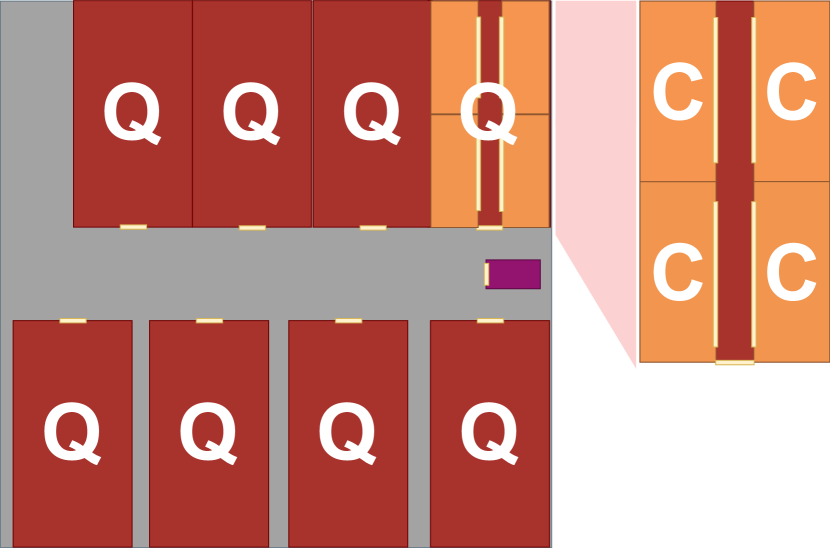
Unlike the cluster tile with its tightly-coupled low-latency memories, the global interconnect uses pipelineable and latency-tolerant links; it is, therefore, less critical and can easily adapt to changing placement and routing pressures. Thus, floorplanning efforts should be focused on the massively replicated compute tile, which is not latency tolerant and highly frequency-critical, therefore dictating the system’s performance, area, and operating frequency. Nevertheless, the hierarchical scale-out strategy can impose additional constraints onto the repeated tile, such as aspect ratio or pin positioning. Figure 2 shows three examples of how different quadrant and top-level organizations can require the cluster tile to take specific aspect ratios, further motivating our experiments.
III Methodology
We use Synopsys Fusion Compiler 2020.09 to synthesize, place, and route the Manticore Snitch cluster in GlobalFoundries’ advanced FinFET technology node for a set of memory placement styles and aspect ratios ranging from very wide (:) to very tall (:). All shown designs target a clock frequency under worst-case conditions (SS, , ) with a core area of . The designs were taken to the route optimization stage, with the tool trying to solve as many DRC violations as possible but without running a sign-off phase. Finally, we evaluate the physically implemented designs in terms of:
- Effective frequency
-
Limits the compute throughput per tile.
- Cell density
-
Limits the placeable logic (tiles) per unit die area.
- #Buffers
-
Increases with expended timing and design rule fixing effort and impacts leakage and switching power.
- Routed wirelength (RtWL)
-
Worsens the transition times, crosstalk, and ohmic losses, requiring more timing and design rule fixing and increasing leakage and switching power.
- #DRC Violations
-
Indicates the routability of the design.
- #Violating Paths/TNS
-
Capture the overall severity and ubiquity of timing violations and increase with the optimization effort required to achieve a given effective frequency.
IV Floorplanning
To arrive at our evaluation floorplans, we will first observe the cluster tile’s architecture by analyzing the interconnectivity of individual design components since these properties will fundamentally impact our target metrics.
Technology-dependent SRAM macros are used to implement all I$ and SPM banks. With 32 of 36 memory macros and of the design’s placeable area, the L1 SPM is the most challenging component to place. Its fully-connected crossbar dominates all other interconnect logic in complexity, providing an individual low-latency link for all master-slave pairs; we can predict that it will be routing-dominated and, therefore, susceptible to low cell density and routing congestion. In addition, this interconnect requires a large unobstructed placement area and for all the SPM macros to be close to it.
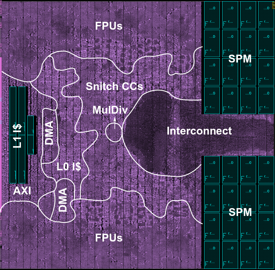
We propose the three representative floorplan styles to explore the QoR of the Manticore Snitch cluster: FP, FP, and FP. The I/O pins are constrained to the left side, and the SPM macros are on the right side, in all floorplan styles. The I$ macros are placed close to the left side not to obstruct the SPM crossbar yet remain accessible to the CCs. Moreover, all styles are vertically symmetric to keep the interconnect easily reachable by all CCs and SPM macros.
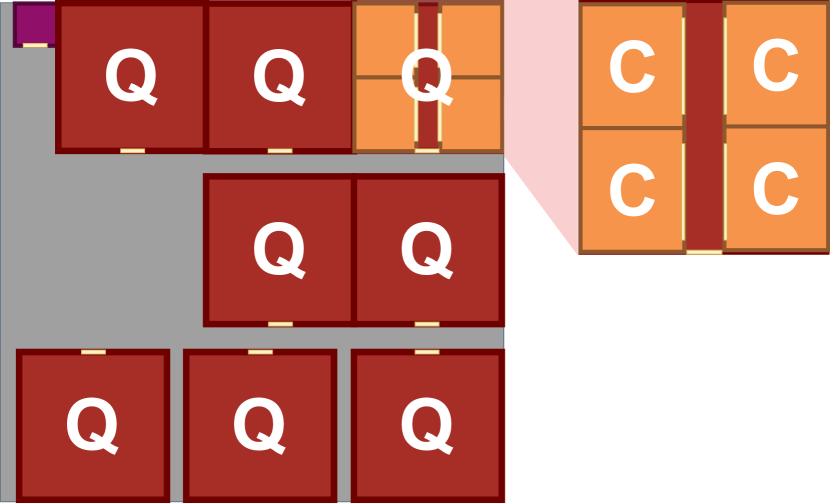
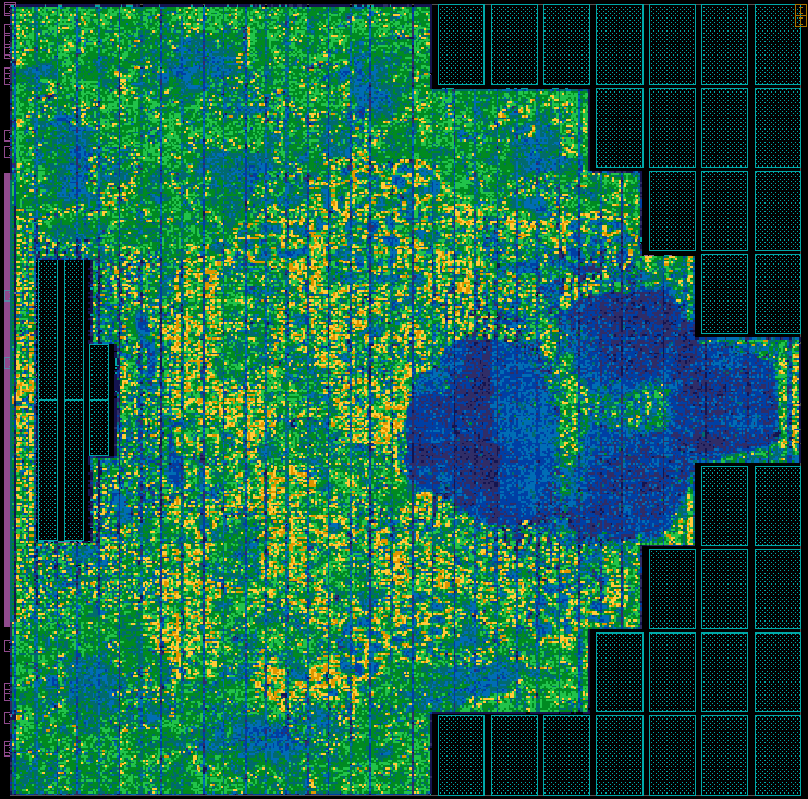
FP, shown in Figure 3, places all SPM memory macros on the right side in a block as compact as possible. It tries to keep the interconnect as close as possible to the right side of the design. This placement style might lead to narrow channels in the center of the design, causing the “pinching” of the interconnect area. Moreover, the excessive macro stacking causes some macros to be far from the standard cell area, which challenges the routing to their pins.
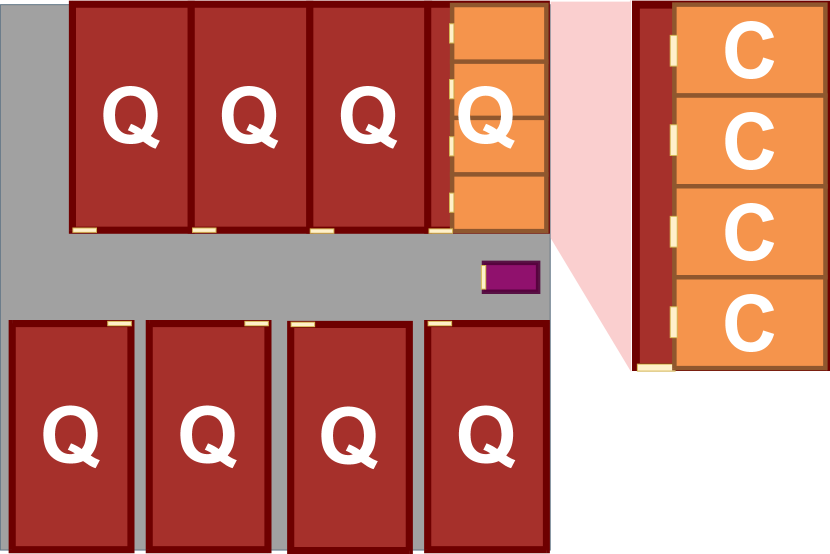
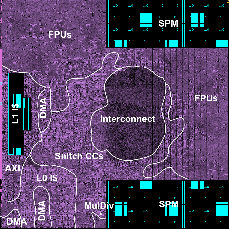
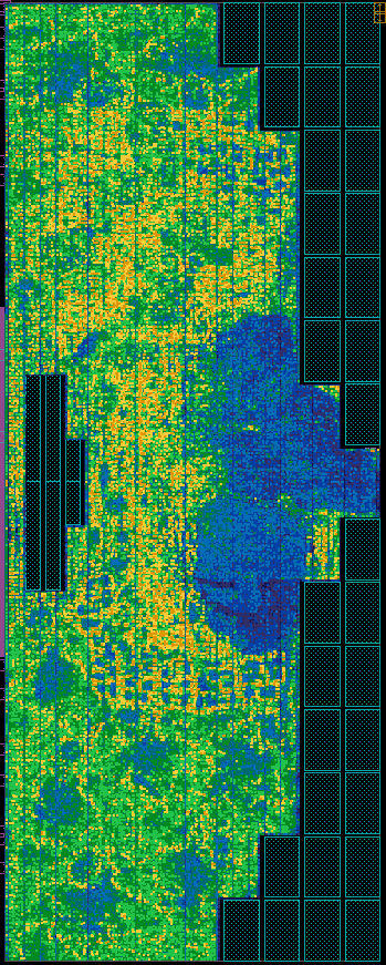
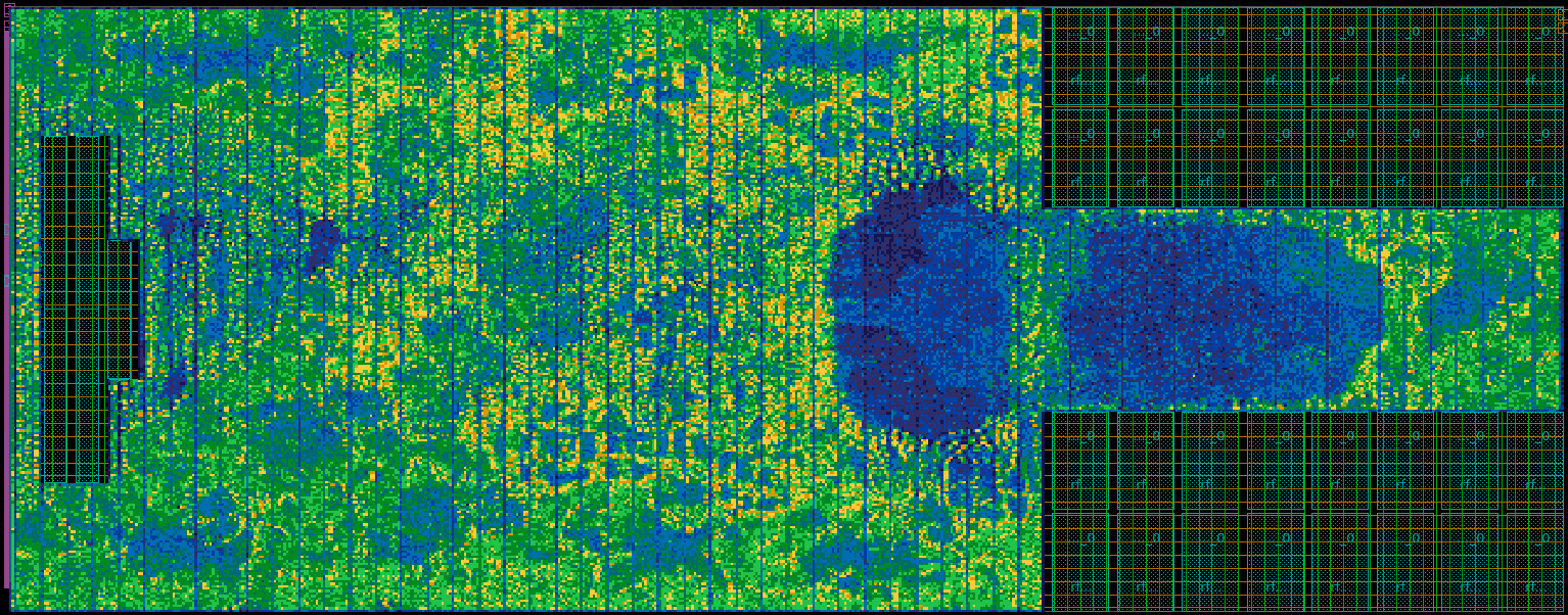
FP, shown in Figure 3, tackles those limitations by leaving a largely unconstrained placement area for the interconnect and keeping all SPM macros easily accessible from the standard cell area. To do so, it places the SPM macros in a block as wide as possible. However, this placement style spreads the macros across the design, which might affect the wire length and the timing.
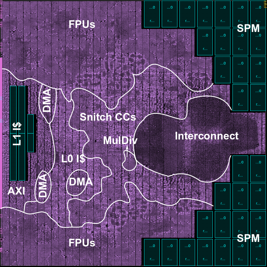
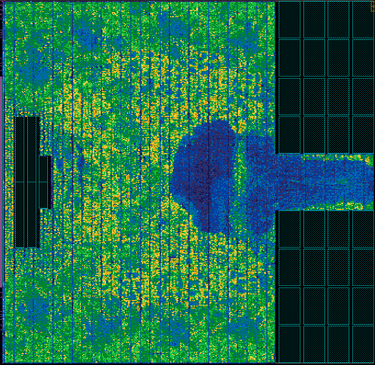
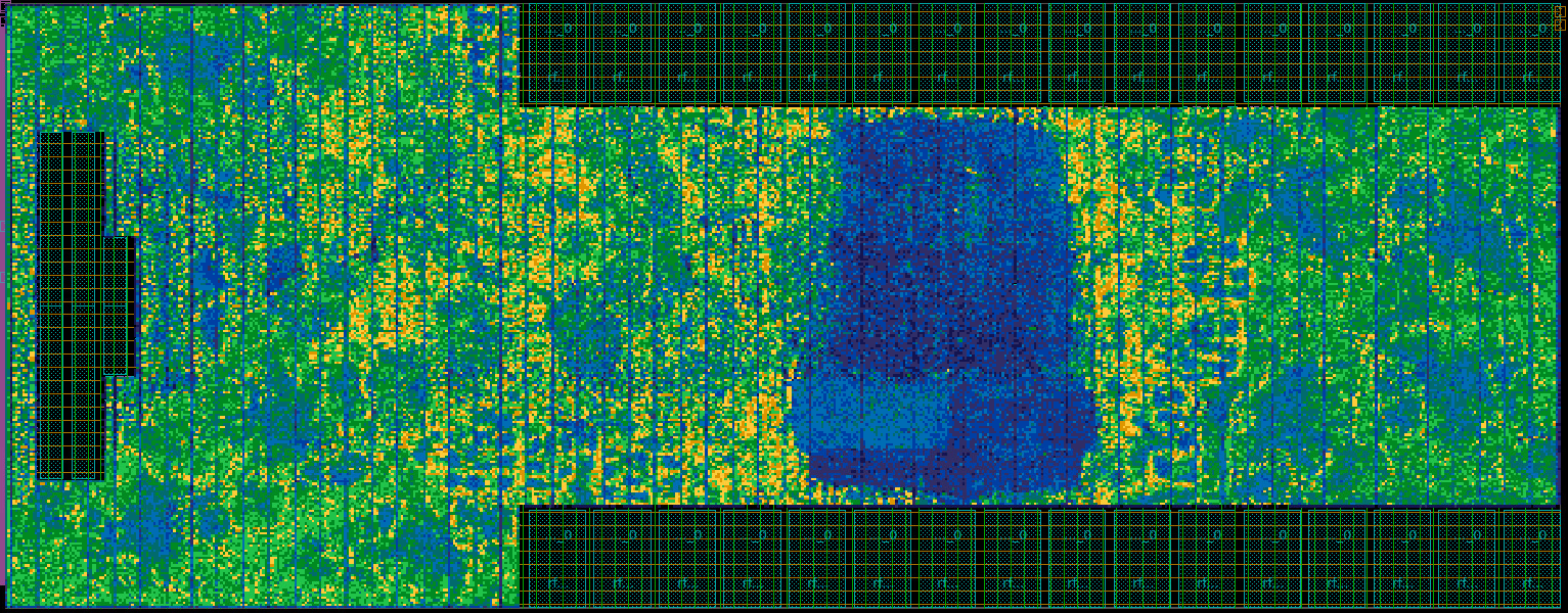
FP, shown in Figure 3, is a midway point between the two previous styles. This floorplan places the SPM macros in a vertically symmetrical “U” shape enclosing the region where the SPM crossbar is placed; this further minimizes their overall distance of the SPM crossbar and avoids excessive stacking. The SPM macros are placed according to samples of the generator function , where represents the -th column of macros in the SPM region, represents the height of the corresponding column, HH is half of the height of the cluster area, and the parameter is chosen so that the SPM macros occupy as many rows as possible (i.e., closing the central channel).
V Implementation Results
This section compares the QoR for our three different memory macro placement styles for a range of aspect ratios. We will then discuss how understanding the aspect ratio scaling of different tile floorplans can help determine an optimal hierarchical top-level floorplan.
V-A Base Floorplan Analysis
Figures 3, 3 and 3 highlight the placement of the main modules of the Manticore Snitch cluster. The interconnect occupies a large central area in the design, encircled by the CCs. The CCs are attracted by the L1 I$ and the SPM crossbar, while the FPUs occupy the remaining area.
The Snitch cluster’s placeable cell area is approximately . The uniform cluster area of implies an average standard cell utilization of over the three base floorplans. The standard cell density maps for all base floorplans are shown in Figures 5, 5 and 5. The low cell density of the densely routed SPM crossbar indicates that the density in the regions where the CCs and FPUs are placed is, in fact, much higher than the average density suggests, peaking at . This puts pressure on the rest of the design, which ends up dense and having to avoid the routing-congested interconnect region.
For Figures 3 and 3, the modules were placed in suitable locations. However, in Figure 3, the lack of space between the interconnect and the L1 I$ macros for the CCs and L0 I$ es results in an asymmetric module placement, where the cores end up on the bottom of the floorplan. Furthermore, the module positions indicate that this floorplan style leads to a cluster particularly sensitive to changes in the aspect ratio in the direction of taller (narrower) clusters since this will further reduce the distance between the crossbar and the L1 I$ macros.
Table I compares those three floorplan styles according to several QoR metrics. FP shows the best QoR overall with a square : aspect ratio, reaching the highest operating frequency, lowest TNS, fewer violating paths, and shorter RtWL. FP reaches comparable results, the main difference being an operating frequency lower than the FP instance. This performance drop is due to pinching of the interconnect by the central channel in the FP instance.
Both the FP and FP instances finished with 38 DRC violations. This low () DRC violation count is expected, since we only run our implementation flow to the route optimization stage. Those violations are spread across the floorplan and can be solved manually in a sign-off step. FP, on the other hand, had 227 violations, many of them shorts concentrated in the interconnect region. Therefore, we consider this instance unfeasible. This high DRC count is due to the interconnect placement between the FPUs and their CCs. There are not enough resources to route those connections through the interconnect region, which leads to a high amount of DRCs and an unfeasible design.
V-B Aspect Ratio Analysis
In this section, we analyze and compare the three floorplan styles as discussed in Section IV for three aspect ratios (width:height)—a tall (:), a square (:), and a wide cluster tile (:)—with a uniform cluster area of . This aspect ratio selection enables a variety of hierarchical scale-out floorplans, e.g., the ones shown in Figure 2. Our findings are summarized in Table I. In addition, we plot four key metrics, effective frequency, RtWL, number of DRC violations, and the number of inserted buffers in Figure 4. Overall, moving away from a square floorplan causes a noticeable QoR degration.
| Aspect Ratio | : | : | : | ||||||||
|---|---|---|---|---|---|---|---|---|---|---|---|
| Floorplan | FP | FP | FP | FP | FP | FP | FP | FP | FP | ||
| Eff. Freq. [] | 888.8 | 886.5 | 875.7 | 927.6 | 939.8 | 940.7 | 921.7 | 909.1 | 925.1 | ||
| TNS | -33.8 | -48.2 | -103.3 | -25.5 | -30.2 | -24.7 | -37.5 | -40.2 | -78.2 | ||
| #Violating Paths | 5352 | 5787 | 6819 | 4890 | 5372 | 4459 | 6163 | 5871 | 8271 | ||
| RtWL | 17.1 | 17.6 | 17.0 | 15.8 | 15.9 | 15.6 | 16.9 | 16.9 | 16.6 | ||
| #DRCs | 36 | 417 | 259 | 38 | 227 | 38 | 654 | 2943 | 86 | ||
| #Buffers | |||||||||||
| Cell Density | |||||||||||
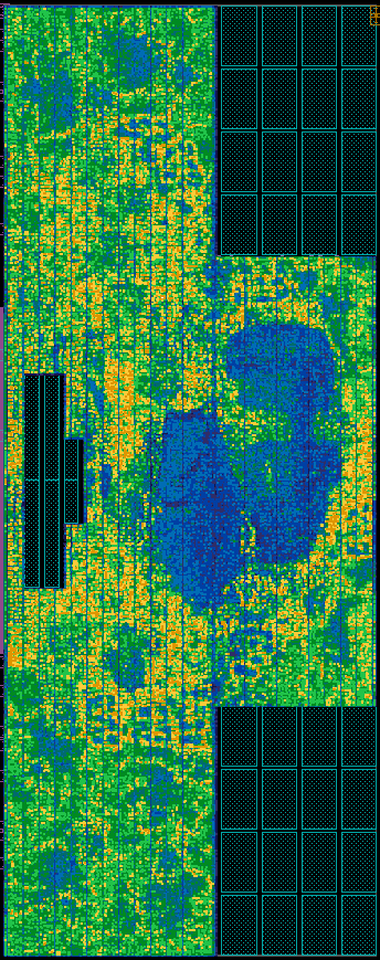
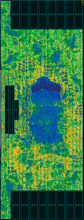


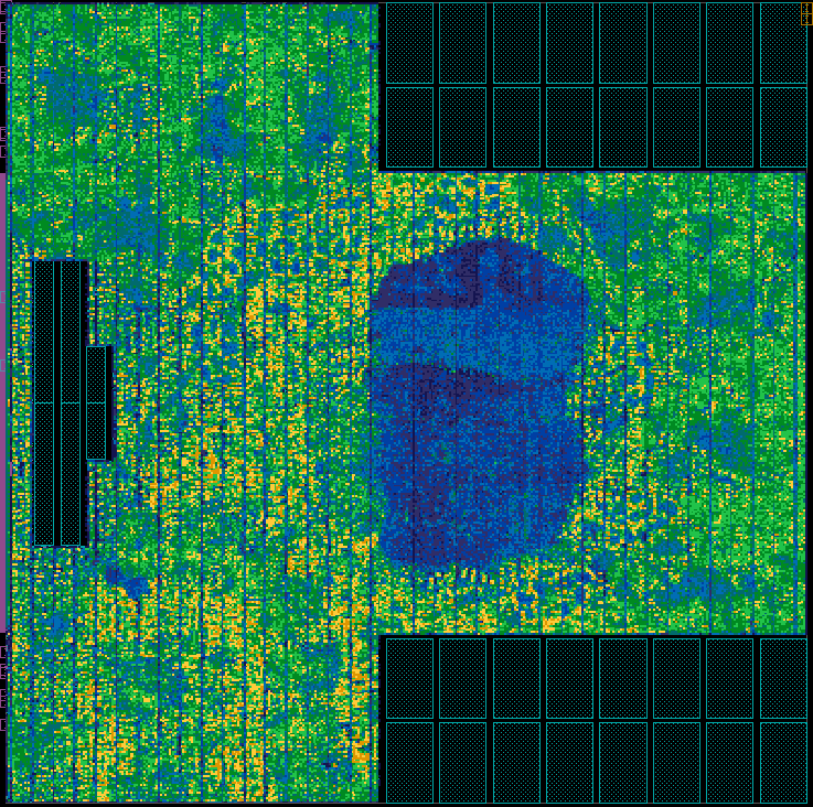
For our three floorplan styles, pushing the floorplan to a tall aspect ratio of :, shown in Figures 5, 5 and 5, degrades the overall QoR more than pushing to a wide aspect ratio of :, shown in Figures 5, 5 and 5. Similarly to the square floorplan FP in Figure 5, the three floorplans FP, FP, and FP for the tall aspect ratio of : in Figures 5, 5 and 5 have an asymmetric module placement: the CCs cannot be placed in the central location between the interconnect and the I$ banks and are squeezed to one side. This placement impacts their QoR. Out of those three instances, FP and FP are unfeasible due to a high DRC violation count. Only FP is feasible, although at an operating frequency lower than the fastest square-shaped instance.
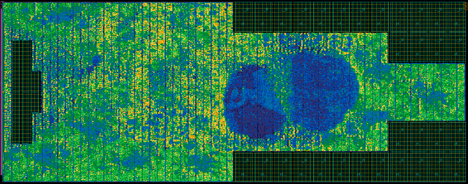
Figures 5, 5 and 5 show the cell density maps for FP, FP, and FP for the wide aspect ratio of :. The smaller height for these floorplans requires the SPM banks to be arranged in more columns causing the fully-connected crossbar (blue region) to be placed more towards the center of the floorplan. The resulting free area on the right side gets filled with FPUs. For both FP and FP, the fully-connected crossbar is squeezed and stretched by the wide SPM bank rows, respectively. Thus, all connections between the CCs and the FPU must be routed through the already congested crossbar area. The lack of routing resources in that area increases the number of DRC violations for FP and FP. In contrast, the arrangement of the SPM banks in the FP instance leads to an undisturbed crossbar placement. This allows the CCs to FPU connections to route around the high routing congestion crossbar area. Nevertheless, the overall feasibility of FP with 86 DRC violations remains questionable.
V-C Hierarchical Design Flow Recommendations
Our analysis shows that the QoR of a soft tile is particularly sensitive to aspect ratio variations and highly depends on the floorplan style, i.e., on the memory macro placement. As the main compute unit, the latency-critical cluster should strive to achieve the best possible QoR. The higher hierarchy levels use latency-tolerant and pipelineable interconnects which can easily be tuned to match the cluster’s performance. However, additional requirements might propagate down the hierarchy when designing the top-level floorplan. For example, the top-level floorplans from Figures 2 and 2 might require larger channels between the bottom row of quadrants to allow the global crossbar to route to a die-to-die interface IP or an HBM PHY, requiring a non-square aspect ratio for the cluster tile. Similarly, the narrow channels between the three rows of quadrants in Figure 2 might lead to congested regions, which implies different aspect ratio requirements for the cluster tile.
Based on our findings, we propose to follow our hierarchical implementation approach: in a first step, the designer should evaluate various cluster-level floorplan styles to explore a set of aspect ratios which enable a variety of top-level floorplans. The knowledge of the achievable cluster-level QoR and optimal floorplans for each aspect ratio then allows the further exploration of a set of top-level floorplans using only soft tile shapes that meet the desired QoR.
VI Conclusions
Typically, modern high-performance accelerator architectures are based on tightly-coupled clusters of PEs, physically implemented as rectangular soft tiles. These tiles are often highly replicated and interconnected with a latency-tolerant NoC to build scalable high-performance computing systems. The tile’s size and aspect ratio strongly impact the achievable operating frequency and energy efficiency. Nevertheless, they should be as flexible as possible to enable a high density solution for the complete design. In this paper, we focus on an open-source, high-performance multicore cluster as a soft tile, which can be used to build a high-performance many-cluster system by cluster replication. Based on architectural analysis, we proposed three floorplan styles which can systematically be adapted to different aspect ratios.
We then explored the QoR of placed-and-routed cluster implementations as a soft tile in the GlobalFoundries advanced FinFET technology node, considering wide (:), square, and tall (:) cluster aspect ratios with all proposed floorplan styles. No single floorplan style leads to good QoR across all aspect ratios. FP is to be used when higher-level tiles require a tall cluster floorplan, and FP is better suited when a wide cluster tile is required. Considering the overall QoR, the best : instance achieves an effective frequency lower than the best square instance, although the large TNS and DRC violation count poses doubts on its feasibility. On the clusters with an aspect ratio :, only the FP instance was feasible, albeit at an operating frequency lower than the best square cluster instance.
Overall, the results suggest that pre-characterizing the building block’s QoR for different aspect ratios and floorplan styles, combined with a preliminary investigation of the top-level layout, can help the designer find top-level hierarchical floorplans that are feasible and achieve high performance.
References
- [1] C.-S. Hoo, K. Jeevan, and H. Ramiah, “Cost reduction in bottom-up hierarchical-based VLSI floorplanning designs,” International Journal of Circuit Theory and Applications, vol. 43, no. 3, pp. 286–306, 2015.
- [2] Y. Lin, S. Dhar, W. Li, H. Ren, B. Khailany, and D. Z. Pan, “Dreampiace: Deep learning toolkit-enabled GPU acceleration for modern VLSI placement,” in 2019 56th ACM/IEEE Design Automation Conference (DAC). Las Vegas, NV, USA: IEEE, 2019, pp. 1–6.
- [3] B. Khailany, H. Ren, S. Dai, S. Godil, B. Keller, R. Kirby, A. Klinefelter, R. Venkatesan, Y. Zhang, B. Catanzaro, and W. J. Dally, “Accelerating chip design with machine learning,” IEEE Micro, vol. 40, no. 6, pp. 23–32, 2020.
- [4] S. Adya and I. Markov, “Fixed-outline floorplanning: enabling hierarchical design,” IEEE Transactions on Very Large Scale Integration (VLSI) Systems, vol. 11, no. 6, pp. 1120–1135, 2003.
- [5] T.-C. Chen and Y.-W. Chang, “Floorplanning,” in Electronic Design Automation, L.-T. Wang, Y.-W. Chang, and K.-T. T. Cheng, Eds. Boston: Morgan Kaufmann, 2009, pp. 575–634. [Online]. Available: https://www.sciencedirect.com/science/article/pii/B9780123743640500175
- [6] P. Ji, K. He, Y. Jin, H. Lan, and C. Li, “An iterative merging algorithm for soft rectangle packing and its extension for application of fixed-outline floorplanning of soft modules,” Computers & Operations Research, vol. 86, pp. 110–123, 2017. [Online]. Available: https://www.sciencedirect.com/science/article/pii/S0305054817301211
- [7] T. Yoshida, “Fujitsu high performance CPU for the Post-K computer,” in Hot Chips, vol. 30. Stanford, CA, USA: IEEE Computer Society, 2018, pp. 1–22.
- [8] J. Choquette, W. Gandhi, O. Giroux, N. Stam, and R. Krashinsky, “NVIDIA A100 tensor core GPU: Performance and innovation,” IEEE Micro, vol. 41, no. 2, pp. 29–35, 2021.
- [9] D. Ditzel, R. Espasa, N. Aymerich, A. Baum, T. Berg, J. Burr, E. Hao, J. Iyer, M. Izquierdo, S. Jayaratnam et al., “Accelerating ml recommendation with over a thousand RISC-V/tensor processors on esperanto’s et-soc-1 chip,” in 2021 IEEE Hot Chips 33 Symposium (HCS), IEEE. Palo Alto, CA, USA: IEEE, 2021, pp. 1–23.
- [10] J. Cortadella, J. de San Pedro, N. Nikitin, and J. Petit, “Physical-aware system-level design for tiled hierarchical chip multiprocessors,” in Proceedings of the 2013 ACM International symposium on Physical Design. New York, NY, USA: Association for Computing Machinery, 2013, pp. 3–10.
- [11] M. Cavalcante, S. Riedel, A. Pullini, and L. Benini, “MemPool: A shared-L1 memory many-core cluster with a low-latency interconnect,” in 2021 Design, Automation & Test in Europe Conference & Exhibition (DATE). Grenoble, FR: IEEE, Mar. 2021, pp. 701–706.
- [12] F. Zaruba, F. Schuiki, T. Hoefler, and L. Benini, “Snitch: A tiny pseudo dual-issue processor for area and energy efficient execution of floating-point intensive workloads,” IEEE Transactions on Computers, vol. 70, no. 11, pp. 1845–1860, Nov. 2021.
- [13] F. Zaruba, F. Schuiki, and L. Benini, “Manticore: A 4096-core RISC-V chiplet architecture for ultraefficient floating-point computing,” IEEE Micro, vol. 41, no. 2, pp. 36–42, Mar. 2021.