A Probabilistic Shaping Approach for
Optical Region-of-Interest Signaling
Abstract
We propose a probabilistic shaping approach for region-of-interest signaling, where a low-rate signal controls the desired probabilistic ranges of a high-rate data stream using a flexible distribution controller. In addition, we introduce run-length-aware values for frozen bit indices in systematic polar code to minimize the run-length without using run-length-limited code. Our compact system can support soft-decision forward-error-correction decoding with excellent spectral efficiency compared with related work based on hybrid modulation schemes.
Index Terms:
Region-of-interest signaling, probabilistic shaping, forward error correction, visible light communication.I Introduction
Region-of-interest (RoI) signaling has been introduced by IEEE 802.15.7m group (TG7m) for vehicular optical camera communication (OCC) systems [1]. In this technique, the low-rate and high-rate data streams are transmitted simultaneously. The low-rate stream is used for RoI identification, whereas the high-rate stream is used for high-speed data communication on the selected RoI. Low-rate and high-rate streams are modulated by hybrid modulation schemes such as twinkle variable pulse position modulation (VPPM), or hybrid spatial phase-shift keying (HS-PSK). In detail, the low-rate stream is modulated by undersampled frequency-shift on-off keying (UFSOOK), undersampled phase-shift on-off keying (UPSOOK), or spatial-2 phase-shift keying (S2-PSK), whereas the high-rate stream is modulated by twinkle VPPM or dimming spatial-8 phase-shift keying (DS8-PSK) [2]. Both streams can be decoded by a dual-camera receiver, where the low-speed camera decodes the low-rate stream, and a high-speed camera decodes the high-rate stream. Hence, the computational load of the single-camera receiver is mitigated.
Dimming support is one of the critical considerations in visible light communication (VLC) and OCC specifications. Dimming can be controlled by adjusting the ON (1’s) or OFF (0’s) ratio, which varies from 0% to 100%. In normal cases, dimming control comprises puncturing and compensation symbol (CS) insertion where many redundant bits are added to the frame, which degrades the achievable rate [3]. In addition, the dimming method in twinkle VPPM and HS-PSK changes the position and duty cycle of groups of high-rate pulses over time. Hence, it is challenging to demodulate twinkle VPPM and DS8-PSK signals on the receiver side because each pulse must be sampled, synchronized, and decoded at rigorous timing [4]. In conventional VLC systems, run-length-limited (RLL) codes keep DC balance with equal 1’s and 0’s in every symbol to avoid long runs of 1’s and 0’s, which causes flicker and clock and data recovery (CDR) issues. In fact, there is a trade-off between ease of implementation and rate loss in RLL codes such as Manchester, 4B6B, 8B10B [5]. Besides, most RLL decoders produce hard outputs for hard-decision (HD) forward error correction (FEC) decoder in joint FEC-RLL based systems, which show poor error-correction performance. A soft-input soft-output (SISO) RLL decoder has been introduced by Kim et al. [6], which produces soft outputs for soft-decision (SD) FEC decoding algorithms to improve the overall system reliability. However, the decoding algorithm of the SISO RLL code is bulky and hard to adopt in VLC receivers.
In this letter, we propose a probabilistic shaping approach for RoI signaling applications based on a flexible distribution controller (FDC) and systematic polar encoder/decoder (SPE/SPD) with run-length-aware (RLA) frozen bit values. The proposed system can simultaneously transmit high-rate and low-rate data with low rate-loss overhead. Besides supporting SD FEC decoders, our system guarantees the flicker mitigation without using RLL code.
II System Model
II-A Proposed system
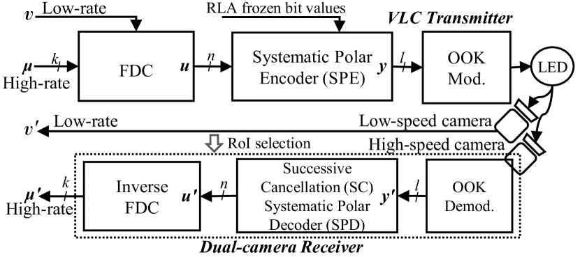
Fig. 1 shows the block diagram of the proposed system. The dual inputs of the system are a high-rate binary sequence and a low-rate signal for . We denote the ratios of 1’s in a -bit FDC codeword and a -bit FEC codeword as and , respectively. In our transmitter, the FDC encodes a binary vector with Bernoulli distribution into a codeword with a desired distribution. Indeed, is different from when the message is encoded by a FEC encoder. We apply an SPE to preserve probabilistic shapes of for the two dimming ranges. In addition, RLA frozen bit values are applied to the SPE to limit the run-length of , instead of using RLL code as in conventional VLC systems. For a dual-camera receiver, a low-speed camera (frame rate 100 frames per second ()) with long exposure time detects the dimming ranges of light-emitting diode (LED) and decodes the low-rate bit sequence, which is used for RoI identification. A high-speed global shutter camera (frame rate 10000 ) decodes the high-rate data stream on the selected RoI connection. An SD successive cancellation SPD (SD-SPD) decodes the codeword for . Finally, the inverse FDC decodes the message for high-rate binary sequence . OOK modulation and demodulation are selected because of their simplicity and popularity.
II-B Flexible distribution controller (FDC)
The distribution controller (DC) modifies the probability of 1’s in a sequence of bits to a desired distribution using arithmetic decompression algorithm. Let where denote the set of binary -tuples with weight . A source model which emits sequences in with probability equal to for . Other sequences of length which are not in have zero probability. Let where denote the set of -bit information words. A one-to-one correspondence is established between information words in and a subset of of sequences in based on the source statistics introduced in [7]. The code-rate loss , which indicates the average number of redundant bits carried by each DC-encoded bit, is given as
|
|
(1) |
where denotes the floor function, outputs the largest satisfying the inequality where .
Fig. 2 shows the rate-loss analysis for various DC code lengths. For code length , it can be seen that when and . Hence, we select 0.1 as a maximum threshold of to design probabilistic ranges of DC outputs. We denote the maximum of the logic-0 probabilistic range as and the minimum of the logic-1 probabilistic range as , where when . For , and . The reason for and is that the low camera on the receiver cannot discriminate the LED ON or OFF states when is close to . In addition, it can be seen that and when . However, we select and use FEC code length = 128, which is compatible with short frame lengths in most VLC specifications.
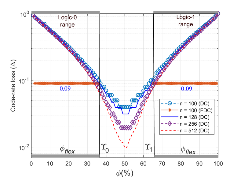
We propose the FDC, which produces codewords with a flexible distribution of , which is denoted as . The can be any value in the logic-0 probabilistic range (] or logic-1 probabilistic range [). A low-rate signal controls which probabilistic range the stays in. For instance, if , the FDC will produce a codeword , which has in the range ; if , it will produce one with in the range . For , let denote how many times larger the codebook of -tuples of weight is than the codebook of -tuples of weight , which is given as
| (2) | ||||
The number of codewords in the codebook of the FDC when and are given as follow
|
|
(3) |
|
|
(4) |
Assume that , we have
|
|
(5) |
|
|
(7) |
To calculate the code-rate loss of the FDC, which is denoted as , from , we replace in (1) with (7), we have
|
|
(8) |
From (8), it can be seen that and are symmetric with respect to when .
II-C RLA frozen bit values for SPC
To create two dimming ranges in an FEC-based system, a systematic FEC encoder should be applied to preserve the two probabilistic shapes of . Furthermore, the run-length of FEC codewords should be limited to avoid flickering at the system’s optical clock. We solve these issues by employing the SPE with RLA frozen bit values. An SPC is specified by (, , ), where is the code length, is the number of information bits encoded per codeword, and is a set of - indices which indicate locations of frozen bits, where }, . Given the SPC with code rate , at a design signal-to-noise ratio (design-SNR), a construction algorithm over an additive white Gaussian noise (AWGN) channel selects best among bit channels for information bit indices, and the remaining channels for frozen bit indices. As the conventional setting, all 0’s are assigned to frozen bits, which increases the 0’s run-length of codewords. Hence, we introduce the RLA frozen bit values, which is addressed in Algorithm 1. As shown, the bit-channel metrics vector , which is created by Arikan’s Bhattacharyya bounds [8], is sorted in ascending order. For frozen bit indices, a bit sequence where the inverse values of bit-0 and bit-1 are placed one after another is assigned. By this setting, the free run of 0’s or 1’s is prevented.
Input:
Vector of bit-channel metrics generated from Bhattacharyya bounds [8].
|
RLL | Optical clock rate | FEC | Bit rate |
|
||||
|---|---|---|---|---|---|---|---|---|---|
| Twinkle VPPM | N/A | 16 kHz | Reed-Solomon (15,11) | 4 kbps | 0.25 (bits/s)/Hz | ||||
| HS-PSK |
|
10 kHz |
|
22 kbps | 0.1375 (bits/s)/Hz | ||||
|
None | 12.6 kHz |
|
11.47 kbps | 0.91 (bits/s)/Hz |
-
HS-PSK: 2 light sources, 8 LEDs for each source. Average spectral efficiency = (Bit rate/(clock rate82)).
III Simulation results
It can be seen from Fig. 2 that with , when for logic 0 and for logic 1. On the other hand, when and . This can be explained by the fact that the codebook size of the FDC is much larger than that of the DC. In short, the FDC can produce two probabilistic shapes under the control of low-rate signal at very low rate loss.
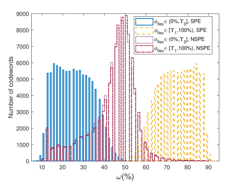
Fig. 3 shows the post-FEC-encoder probabilistic shapes. As can be seen from the figure, the two probabilistic ranges, and , are not overlapped when the the FDC outputs are encoded by the SPE. In contrast, they overlap and stretch on the wide range, , and tend to converge to the mid-range when a nonsystematic polar encoder (NSPE) is applied with the FDC. To enable low-rate communication from the two dimming ranges, the probabilistic ranges must not overlap each other to be discriminated by the low-speed camera on the receiver. Therefore, the SPE is selected as the FEC encoder in our system.
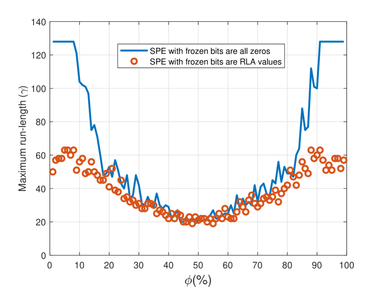
We also evaluated the maximum run-length of codewords encoded by the SPE, which is denoted as . As shown in Fig. 4, when the RLA values are assigned to frozen bits, is reduced by a factor of 2.03 compared to when all-zeros are assigned to them. To avoid flicker, the LED’s brightness should change within the maximum flickering time period (MFTP 5ms) [5]. Hence, with = 63, our system guarantees the flicker-free operation with optical clock rates higher than 12.6 kHz without using an RLL code.
Table I compares the proposed method with related work addressed in the image sensor communication PHY-IV modes added to TG7m [2]. The clock rate of our system (minimum is 12.6 kHz) is almost equivalent to that of related approaches. Given the fact that FEC codes with code rates have been introduced in PHY II modes of IEEE 802.15.7 and PHY-IV modes of TG7m [5, 1], we have evaluated our system with a polar code (128,100) with , where the reason for short code length is explained in section II-B. With the FDC’s rate loss , our system achieves a spectral efficiency 0.91 (bits/s)/Hz, which is better than systems based on hybrid modulation schemes.
Without the support of RLL code (none-RLL), the CDR issues should be considered. Let denote the number of required image frames that the high-speed camera uses to synchronize the timing and decode the bit sequence on the receiver. In our previous work [9], experimental results showed that when there is a clock difference between the transmitter and receiver, stable bit error rate (BER) performance is achieved with . Fig. 4 shows that the transmitted bit sequence in our system has maximum run-length = 63. It can be seen that by referring to , we can set to guarantee the CDR in case of a long run of 1’s or 0’s appears in the bit sequence.
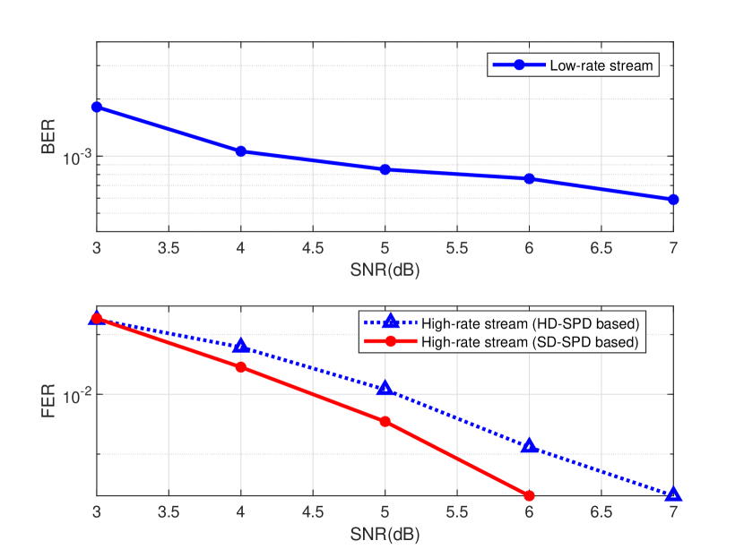
The fact that two cameras use different mechanisms in demodulating the signals, we applied two different AWGN channel models to estimate the BER and frame error rate (FER) performances of the low-rate and high-rate data streams. Fig. 5 shows the BER performance of the low-rate stream which is estimated from the overlap probability between the logic-0 and logic-1 probabilistic ranges of at different SNRs, without the support of error-correction scheme. Meanwhile, the FER of the high-rate stream is calculated when data are decoded by the SD-SPD and the inverse FDC. The BER performance of the low-rate stream can be improved with and if the system affords a higher code-rate loss. Fig. 5 also shows that the coding gain of SD-SPD-based and HD-SPD-based systems differ by 1 dB when FER = 2E-4. In brief, due to the none-RLL feature, SD FEC decoders can be applied in our system to enhance system reliability.
IV Conclusion
In this letter, we introduced a probabilistic shaping approach applied for RoI signaling. The desired flexible distribution of high-rate bit sequences are controlled by low-rate signal controls in the FDC. The SPC with the RLA frozen bit values minimizes the run-length and preserves probabilistic shapes created by the FDC. The low-speed camera decodes the low-rate data from two dimming ranges to identify the RoI, and then the high-speed camera decodes the high-rate data stream on the selected RoI. The proposed system achieves extremely good spectral efficiency with SD FEC decoding support, while the flicker mitigation is guaranteed without RLL code.
References
- [1] M. D. Thieu, T. L. Pham, T. Nguyen, and Y. M. Jang, “Optical-RoI-signaling for vehicular communications,” IEEE Access, vol. 7, pp. 69 873–69 891, 2019.
- [2] T. Nguyen, A. Islam, T. Yamazato, and Y. M. Jang, “Technical issues on IEEE 802.15.7m image sensor communication standardization,” IEEE Communications Magazine, vol. 56, no. 2, pp. 213–218, 2018.
- [3] H. Wang and S. Kim, “Dimming control systems with polar codes in visible light communication,” IEEE Photonics Technology Letters, vol. 29, no. 19, pp. 1651–1654, 2017.
- [4] J. Noh, S. Lee, J. Kim, M. Ju, and Y. Park, “A dimming controllable VPPM-based VLC system and its implementation,” Optics Communications, vol. 343, pp. 34–37, 2015.
- [5] S. Rajagopal, R. D. Roberts, and S.-K. Lim, “IEEE 802.15.7 visible light communication: modulation schemes and dimming support,” IEEE Communications Magazine, vol. 50, no. 3, pp. 72–82, 2012.
- [6] H. Wang and S. Kim, “Soft-input soft-output run-length limited decoding for visible light communication,” IEEE Photonics Technology Letters, vol. 28, no. 3, pp. 225–228, 2015.
- [7] T. V. Ramabadran, “A coding scheme for m-out-of-n codes,” IEEE Transactions on Communications, vol. 38, no. 8, pp. 1156–1163, 1990.
- [8] E. Arikan, “Channel polarization: A method for constructing capacity-achieving codes for symmetric binary-input memoryless channels,” IEEE Transactions on information Theory, vol. 55, no. 7, pp. 3051–3073, 2009.
- [9] Y. Shiraki, T. G. Sato, Y. Kamamoto, T. Izumi, Y. Nakahara, K. Kondo, and T. Moriya, “A demodulation method using a gaussian mixture model for unsynchronous optical camera communication with on-off keying,” Journal of Lightwave Technology, vol. 39, no. 6, pp. 1742–1755, 2021.