LaserSVG: Responsive Laser-Cutter Templates
Abstract.
Laser cutters take vector data for the shapes they cut or engrave as input, however, re-using a given design with different material or on a different machine requires adaptation of the template. Unfortunately, vector drawings lack the semantic information required for an automated adjustment to new parameters, making the manual adjustment a tedious and error-prone process for end-users. We present LaserSVG, a standard-compliant vector-based file format, software library, and authoring tool to specify, generate, exchange and re-use responsive laser-cutting templates. With LaserSVG, designers can easily turn their vector-drawings into parametric templates that end-users can easily adjust to new materials or production parameters. Our tools provide various functions for parametric design that allows end-users and designers to adapt objects while ensuring overall consistency of the results.
1. Introduction
Laser cutters are a key technology for personal fabrication (Baudisch and Mueller, 2017) and likely the most popular machines available in Fab Labs. In the 2017 FabAcademy class, 80% of the final projects made use of a laser cutter (Gershenfeld, 2017). Laser cutters work on vector data that defines where the material should be cut, and which parts should be engraved. Community platforms like thingiverse.com or grabcad.com share numerous designs for a wide variety of projects. These templates are commonly exchanged in the form of vector drawings and mostly use PDF, DXF, or SVG as a file format.
These templates, however, are usually made for a single type of material (e.g., inch plywood) and tweaked towards a specific type of laser-cutter. If an end-user downloads such a template to fabricate it from 3mm plywood, and a machine with a different kerf (i.e., the width of the cut), she has to adapt and tweak it to her specifications. Recent findings have shown editing digital models, such as SVG files, to be one of the biggest hurdles when using digital manufacturing technology (Mahapatra et al., 2019). Professional CAD environments, such as Rhino (Rhinoceros, 2018) or Autodesk Fusion 360 (Autodesk Fusion 360, 2019) support parametric design features to facilitate such changes to 2D or 3D designs. However, such features require designers (experienced users making the original model) and end-users (people using and adapting a designer’s models) to use the same CAD environment. In practice, designers oftentimes use more advanced software environments and features that end-users do not want to be exposed to. Instead of sharing their parametric 3D model, designers therefore only share the 2D vector graphics drawings for laser cutting on platforms like Thingiverse. These vector graphics files do not require advanced tools but are static and lack the semantics of the underlying model, making it hard to adjust the design to new material or machine properties.
If an end-user, for example, downloads the SVG drawing of the miniature bench design shown in Figure 1 and wants to manufacture it from a piece of material that is of different thickness than what the designer created it for, the end-user has to adjust eight rectangles (mortises) and 16 path segments (tenons). Simple adjustments to laser cutter templates therefore often entail a large number of changes as all edges that correspond to material thickness need to be identified and adjusted. Similar adjustments are required to ensure a tight fit (i.e., press-fit) when fabricating a model with a laser cutter that has a different kerf (Roumen et al., 2019).
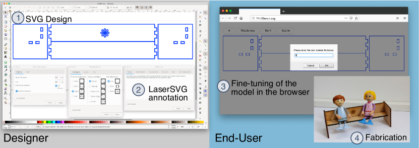
We propose LaserSVG, an extension to the SVG file-format that significantly facilitates creating and adapting parametric vector graphics designs for laser cutting. We will illustrate our contributions with an example. A designer creates a vector drawing of the parts forming the miniature bench as shown in Figure 1a. In order to make it simpler for end-users to adjust the template to different material or machine parameters, the designer loads the SVG drawing into Inkscape111http://www.inkscape.org if not already designing in this vector drawing application. The LaserSVG plug-ins offers various options to encode the additional information required to automate common changes when working with laser-cutter templates. For example, the designer can specify which edges of the design correspond to the thickness of the material that is being used to build the bench. In our example, these are the height or width of the mortises in the side panels of the bench, and the length of the tenons. This information is stored in the SVG drawing.
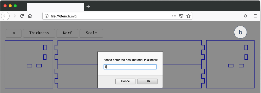
To avoid end-users having to install additional software to adjust a template to their needs, LaserSVG templates embed a JavaScript library that turns the SVG file into a self-contained, responsive, and parametric template (Figure 1b). When an end-user opens a LaserSVG file in a web-browser (Figure 1c), this library renders a simple menu that allows her to alter common fabrication parameters to adjust the design to materials and machinery available to her. The rendering of the model is updated accordingly and can easily be exported for fabrication either as a regular SVG file using the browser’s “save-as” functionality or directly through the “print” menu.
1.1. Contributions
In this paper, we present three contributions:
-
(1)
We introduce LaserSVG, a fully SVG-compliant file-format specification that encapsulates additional parametric features to facilitate automated adjustment for SVG models for laser cutting.
-
(2)
We contribute a JavaScript library to turn the LaserSVG file-format into a self-contained, responsive, and parametric design template that allows fine-tuning LaserSVG models in the web browser222Available as open source at https://github.com/florianheller/lasersvg.
-
(3)
We contribute a suite of Inkscape plug-ins to annotate traditional SVG files with parametric features and turn them into LaserSVG templates333Available as open source at https://github.com/florianheller/LaserSVG_Inkscape.
In the remainder of this paper we discuss the novel opportunities that come with our responsive laser-cutter file format, the workflow to make designs responsive, and an evaluation with real-world laser cutter templates.
2. Related Work
Laser cutters work on vector data that defines where the machine will cut or engrave things. Designing objects to be manufactured with a laser-cutter, therefore, requires the creation of 2D vector drawings. This process, however, is challenging (Johnson et al., 2012; Mahapatra et al., 2019) and often leads to non-fitting results which then have to be re-adjusted, wasting time and material.
Although being a 2D tool, the laser-cutter is also a very handy tool to create 3D structures which adds additional complexity to the design of the 2D shapes if these need to interlock properly. The research community developed two approaches to address this problem. The high-level approach takes 3D-models and breaks them down to components that can be manufactured on the laser-cutter, while the low-level approach directly works on 2D data. Crdbrd (Hildebrand et al., 2012) and the work by Schwartzburg et al. (Schwartzburg and Pauly, 2013), for example, take a 3D model and convert it into planar sections. Mesh2Fab (Yang et al., 2014) assists in the disassembly of the 3D-models into components that can be manufactured from a target material, while Platener (Beyer et al., 2015) replaces parts of the 3D-model with elements that can be laser-cut with the goal to speed up the production process compared to 3D-printing only. These approaches can integrate material and machine parameters into their disassembly process. However, changes in material thickness require the disassembly process to run again, while actually, only a series of edges need to be adapted in the 2D template. CutCAD (Heller et al., 2018), on the other hand, uses an inverse approach and starts from 2D shapes to create 3D objects by adding the required interconnections automatically.
To simplify the common task of creating enclosures and boxes, we have scripts of variable complexity at hand. The MakerCase.com web-tool creates simple rectangular boxes based on user-specified dimensions with parametric joints. The user can select whether the design should come with t-slot-joints, finger-joints, or without connections between the faces. The Boxes.py (Festi, 2013) script provides more options regarding the shape of the resulting object and the joints. For example, it is not limited to connections on the edge of a shape, but can also create mortise and tenon joints. Nevertheless, the user is limited to the functionality of the script, e.g., it does not support arbitrary shapes. As such cases are often used as an enclosure for self-built devices, Weichel et al. (Weichel et al., 2013) propose to take the bill of materials and the program code to generate a custom enclosure for a specific device.
Many projects also investigated the parameterization of designs, such that end-users can easily customize them to their needs. A popular tool for designers is the Grasshopper plugin now included directly into the Rhino design environment, which allows designers to include algorithmic and parametric elements into their 3D models. Kyub (Baudisch et al., 2019) is a 3D design environment tailor-made for laser-cutting which incorporates many best practices as tools to simplify the design. The Thingiverse Customizer (MakerBot, 2018) parses OpenSCAD scripts with specifically annotated variables and generates a graphical user interface for end-users to adjust these exposed variables. The adapted model can then be sent off for 3D-printing. As writing OpenSCAD models is rather complex to understand for beginners (Yeh and Kim, 2018), other scripting approaches have been presented that build on the known knowledge of JavaScript (Kato and Goto, 2017) and HTML (Yeh and Kim, 2018). Both CraftML (Yeh and Kim, 2018) and f3.js (Kato and Goto, 2017) are designed to provide a low entry threshold to attract beginners to parametric design of 3D models, while at the same time providing a high ceiling so as to accompany designers up to professional level.
Parametric approaches exist for two-dimensional models as well. Sketch-n-Sketch (Hempel and Chugh, 2016) is a script-based approach that stores the design as a lambda-calculus-program in the little programming language, which the user can adjust using a direct manipulation interface to match its expected output. Seamly2D (Telezhinskyi, 2018) is a drawing application for responsive sewing patterns with the goal to make tailor-made clothing based on a series of body measurements. Joinery (Zheng et al., 2017) is a tool that designers can use to assign various types of joints to the edges in an SVG drawing. These projects, however, still require the use of specialized software to adjust the templates to end-users needs.
Sharing designs is a core part of the Maker movement, but bare replication of the object can already be complicated due to a lack of information, context, or capabilities (Wakkary et al., 2015). Furthermore, most of the shared laser-cutter templates consist of the flattened files, while sharing the underlying 3D model is uncommon for these projects (Roumen et al., 2019). Therefore, it would be helpful to extend these currently static 2D exports with additional information, such that common parameters can easily be adapted.
SVG Parameters (Schepers, 2009) and Parametric SVG (Wiszniewski, 2016) introduce the use of variables and calculations in regular SVG files, making it possible to adjust their appearance. In LaserSVG, we extend this idea by making the templates responsive such that they can easily be adjusted without additional software, and by including functionality that specifically simplifies the creation and use of laser-cutter templates.
3. Laser Cutter Templates
To determine relevant features commonly used in laser cutter templates, we created a dataset of 40 real-world laser-cutter templates from Thingiverse. To generate a random set of models, we performed a search for the terms “laser cut” on Thingiverse in July 2020, which resulted in 7046 entries. From this corpus we created a sample by creating three sets of 30 models by taking every 235th entry from the search result, using a starting offset of 0, 50, and 100.
From these 90 models, 13 only contained files for 3D printing, and 37 only used the laser-cutter in 2D, not for interlocking pieces, leaving 40 templates that build 3D-structures with interlocking pieces.
We looked at the types of construction techniques that were used in these interlocking templates, with some templates combining multiple of these. The three most common features were mortise and tenon-joints (23/40, 58%), finger joints (13/40, 33%), and slotting or lap joints (10/40, 25%) as found in cross-section models. Two models used living hinges to bend material.
We also looked at whether the template contains only paths to be cut, or if there are additional elements to be engraved. In total, 25 templates just contained cut information and 15 (37.5%) used the cut and the engrave functionality of the laser-cutter.
3.1. Material Thickness and Scale
A common adjustment for laser-cutter templates is to fit these to a new material thickness, for example, because the template is designed for a material thickness defined in inches and there is no exactly matching metric counterpart, or because the end-user just does not have the specified thickness at hand. Adjusting a laser-cut model easily leads to faulty designs and frustration: users often know what value they want to change (e.g., material thickness), but not how this change would reflect in the design. To adapt a simple mortise and tenon joint as in the miniature bench example (Figure 1), the end-user has to consider which dimension of the mortise rectangle represents the material thickness. Finding all these thickness-dependent elements and adjusting them to other dimensions is a tedious and error-prone process as it requires building a geometrical understanding of the model. LaserSVG allows the designer of the template who created the object, or somebody else that has a clear concept of the object’s geometry, to add this information to the file in order to simplify subsequent adjustments of the thickness parameter. As shown in Figure 2a, the LaserSVG editor supports annotating thickness information in the SVG file-format. The LaserSVG library embedded in the template uses this information to allow end-users to adjust the template to personal preference or available materials right in their web-browser (Figure 2b).
These annotations also allow for a thickness-aware scaling function that leaves thickness-annotated elements untouched when scaling the SVG model to a different size while using the same material.
3.2. Kerf
Sharing laser-cutter templates also means that the item may be fabricated on a machine that is different from what the original design was made for. To make a template robust (Arvidsson and Gremyr, 2008; Roumen et al., 2020), i.e., universally adaptable to a wide variety of materials and laser-cutters, we need to consider the kerf: the width of the cut which depends on the material and on the type of laser-cutter machine (Roumen et al., 2019; Yilbas, 2001). Compensating for kerf ensures the tightness of fit for so called “press-fit” joints that do not require the use of adhesives. Although the kerf of a laser cutter is thin, it still is about 0.2mm thick. This means that when cutting a rectangular piece that is designed to be 100mm wide, the result will have a width of 99.8mm (0.1mm on every side).
When using, for example, finnboard material, typically cut with a low resolution and high speed, the roughness of the cut leaves enough material for a solid connection making the kerf negligible. However, when cutting the same model from acrylic, which usually requires a higher resolution and slower speed, the edges will be much smoother resulting in a lack of friction to hold the pieces together.
We introduce markers for designers to annotate the affected kerf edges in the LaserSVG editor (Figure 2a). These annotations allow the LaserSVG model to shrink or grow these edges when end-users adjust the kerf parameter in the web-browser.
3.3. Parametric Joints
The design of an SVG model for laser cutting is a tedious process. For example, the creation of matching finger joints between all adjacent faces of a box (cf. Figure 10d). Furthermore, end-users might want to adjust the interconnection by changing the size or the number of fingers, or change the type of joint from finger-joint to a t-slot-joint to increase the stability of the object. LaserSVG therefore automates the creation of parametric joints of interchangeable type. Figure 3a shows how a designer uses the LaserSVG editor to add a parametric joint to her design. End-users simply alter the type of joint using a simple menu available when opening the LaserSVG file in a web-browser (Figure 3b).
3.4. Laser Cutter Processing Options
Laser cutter drivers use certain properties of the vector graphics elements to discern between those that need to be cut and those that are to be engraved. The Trotec driver, for example, uses the outline color to determine which lines need to be cut, while the Epilog driver uses the stroke width for the same purpose. Therefore, LaserSVG introduces cut and engrave options for designers to label paths that require cutting or engraving respectively. In contrast to line color and thickness, these tags are not machine specific. LaserSVG can apply manufacturer-dependent styling options to make a template compatible with the laser cutter at hand.
Overall, similar control over the aforementioned parameters can be found when creating objects in parametric environments such as Rhino (Rhinoceros, 2018) or Kyub (Baudisch et al., 2019). However, these require sharing the 3D-model information, which is uncommon for laser cutting purposes (Roumen et al., 2019). Additionally, end-users have to use the same or an interoperable CAD environment as the one used by the designer. In contrast, LaserSVG is fully compatible with the widely adopted SVG file-format, and allows end-users to adjust designs by simply opening them in a web-browser.
4. The LaserSVG File Format
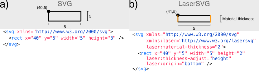
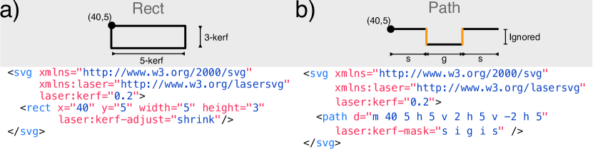
A main objective of LaserSVG is to integrate the features into an existing widely adopted file format, SVG, such that designers and makers can rely on the tools they already know and interoperability with fabrication tools is guaranteed. Key to our approach is that the SVG-format “allows inclusion of attributes from foreign namespaces on any SVG element” (Dahlström et al., 2011b). Additionally, SVG drawings can be scripted and made interactive using JavaScript (Dahlström et al., 2011a). Even when an SVG viewer or editor does not support JavaScript or some custom SVG attributes, it is supposed to include these unknown attributes in the document object model (DOM) and preserve this information when exporting the SVG file. This means that a LaserSVG file will be handled just like a regular SVG drawing by any software that does not implement our extension. For example, if you load a LaserSVG-file into Inkscape, all attributes are kept and saved after the drawing has been changed. Figure 4 shows respectively the SVG code for a basic rectangle (basic mortise joint) and LaserSVG code for a parametric version of that rectangle. The LaserSVG editor (see Section Editing Tools) facilitates the conversion from standard SVG to LaserSVG.
All LaserSVG attributes and scripts can be included by adding xmlns:laser="http://www.w3.org/lasersvg" to the opening <svg>< tag. All information that is included in addition to the standard SVG information is thus stored in the laser namespace. Our custom attributes are, therefore, prefixed with “laser:”.
4.1. Material Thickness
To tag a specific edge as being of material thickness, we have to consider two cases: basic shapes and custom paths. For standard shapes like rectangles, circles, or ellipses, designers specify which dimensions correspond to material thickness by adding this dimension to the thickness-adjust attribute of the shape (Figure 4b). Similar to the resize property in CSS3, this property takes none, width, height, and both as values. In the SVG file format, rectangles are positioned by their top-left corner, which means that adapting the width or height results in changes towards the right and bottom respectively. Therefore, LaserSVG makes it possible to add a resize origin attribute to rect-objects, which takes right, bottom, bottom-right, and center as values to scale the rectangle in the specified direction when changing parametric dimensions. For more complex parametric shapes, designers can always switch to a more powerful custom path description.
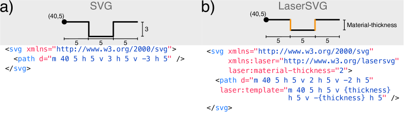
Contour data for a path in SVG is stored in the “d”-attribute of that path object. This path description consists of a series of commands, including move (m), lineto (l), arc (a), and curve (c), which can either be specified in absolute (capital letter) or relative coordinates (lower letter). As we want certain path segments to be parametric, LaserSVG adds a template attribute which contains the same path description as the “d”-attribute, but with the possibility to replace coordinates with {thickness} labels for edges that are of material thickness (Figure 5). Paths in LaserSVG therefore have two path descriptions, one with static data (“d”) and one augmented with parameters (“template”). This duplicate information ensures traditional SVG viewers and editors, not supporting LaserSVG, can still render and make changes to the file. The {thickness} label can also be extended with calculations within the curly brackets around the statement, such as {0.5 * thickness} or {thickness + 2}. As the label can replace any coordinate in the path description, we can compensate for a thicker material by adjusting the origin of the path in the initial move command (m) of the contour data. Sometimes it is necessary to perform more complex calculations to keep an element at its place when changing the thickness, for example when working with triangular shapes whose center of rotation is not located at half of each dimension. In between the curly braces the SVG file format also supports JavaScript code, such as variable assignments and access to mathematical functions. This allows for advanced parametric LaserSVG specifications, such as l{Math.cos(Math.PI/3)*thickness} {Math.sin(Math.PI/3)*thickness}. In contrast to assigning basic parameters to path segments and dimensions using point-and-click tools, advanced statements are entered by the designer through text fields available in the LaserSVG editor. The thickness can be assigned globally through the material-thickness-attribute in the root node of the SVG document, or, if needed, per path if the template is supposed to be fabricated using multiple materials.
4.2. Kerf Adjustment
Similar to the material-thickness tags, LaserSVG introduces a kerf-adjust tag to allow for precise fits between laser cut joints. For example, to ensure a press-fit between a mortise and tenon, the mortise should shrink and the tenon should grow by the kerf-width of the laser cutter. For basic shapes we introduce a kerf-adjust SVG attribute which takes either none, shrink, or grow as value for the entire shape. Paths can have a kerf-mask SVG attribute, marking path segments that need to be adapted and the direction of that change. The mask consist of one letter for each path segment, which can either be i to ignore, g to grow, or s to shrink the corresponding path segment. Capital letters represent a full kerf-width while lower-case characters represent an adjustment by half the kerf-width. For example, assigning the mask attribute "G i G i" to a rectangular path with contour description "template =" M5 5 l0 10 l{thickness} 0 l0 -10 l-{thickness} 0"", would grow the width by the kerf-width of the laser cutter. This results in a rectangle that is exactly 10mm high after laser cutting.
4.3. Action
LaserSVG introduces the action attribute to label SVG elements for either cutting (cut) or engraving (engrave). A stylesheet ensures these SVG elements are then rendered according to the specifications of the laser cutter driver. Loading the stylesheet for a Trotec laser in the SVG file, for example, renders all elements labeled with cut in blue and elements to engrave will be filled black and outlined in red. In contrast the Epilog stylesheet ensures cut elements are rendered with a thickness of .076 mm (hairline) while engrave elements are filled black. Currently our stylesheet covers these two manufacturers, but it can easily be extended to support the specifics of other drivers. In case the properties conflict, end users can then switch between stylesheets by simply specifying the type of laser cutter at hand.
4.4. Parametric Joints
LaserSVG introduces higher-level attributes to SVG path elements that replace an edge with a specific joint. This allows end-users to change the type of joint, while avoiding the tedious design skills that are required to do this manually. To support parametric joints, several attributes are available in LaserSVG : The joint attribute assigns an ID to the edges of two elements that join together. This allows the LaserSVG editor to keep parameters in sync and ensures, for example, that the two edges have the same joint-type. The joint-type attribute specifies the type of joint that should be rendered instead of the original edge. Supported values in the current LaserSVG version include (compact) finger-joints, t-slot-joints, and flaps (cf. Figure 7). The joint-direction attribute specifies which side of a joint is drawn. For example, in the case of a finger-joint, the outside direction adds the fingers to the edge of a face while the inside direction provides the corresponding notches. As rectangular shapes are frequently used in SVG models, LaserSVG offers the possibility to define a joint type for each side, e.g., joint-top-type and joint-top-direction, which avoids requiring the designer to convert the rectangle into single paths. All generated joints paths also come with a LaserSVG template description, embedding thickness tags for automated adjustments as explained above.
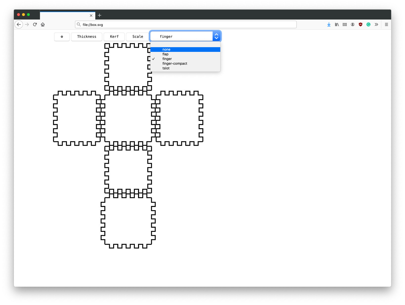
Table 1 offers a detailed overview of all LaserSVG attributes and whether they can be assigned globally in the root node or per SVG element. Some of the attributes can easily be changed by the end-user as we will describe in the following section.
| Attribute | Scope | |
|---|---|---|
| Element | Global | |
| material-thickness | ✓ | ✓ |
| kerf | ✓ | |
| scale | ✓ | |
| origin | ✓ | |
| kerf-adjust | ✓ | |
| joint-type | ✓ | ✓ |
| joint-direction | ✓ | |
| joint ID | ✓ | |
| action | ✓ | ✓ |
| action-value | ✓ | ✓ |
5. Self-Contained Responsive LaserSVG templates
The LaserSVG file-format is an extension to the standard SVG format and does not require end-users to install additional software to make adjustments to SVG models for laser cutting. Instead, a LaserSVG template is a self-contained, responsive format that, when opened in a standard web-browser, renders GUI elements to adjust the contained SVG model. Therefore, we implemented a JavaScript library that is included in any LaserSVG file and implements two dynamic functions. First, it renders a dynamic menu that appears if the SVG file is opened directly in a SVG renderer that supports JavaScript, i.e., a regular web-browser (see Figure 2b). These menu items offer features to adjust parameters in the current LaserSVG file. This end-user menu is not shown when the designer opens the LaserSVG file in the LaserSVG editor or a traditional SVG editor. Second, the library interprets all “laser:” attributes and ensures the SVG model is rendered and updated according to the set parameters, such as adaptive thickness, thickness-aware scaling, kerf-adjustment, and parametric joints.
6. LaserSVG Editor
In this section we will describe how our suite of Inkscape plug-ins supports the designer in annotating the drawing with the additional LaserSVG tags to turn it into a parametric template. As Inkscape’s plug-in API only provides a limited set of user interface elements and no interactivity in the plug-in windows, we decided to split functionality over several panels. To turn the current drawing into a LaserSVG template, the designer starts by specifying the material thickness the model is designed for, a default kerf-width, and whether the template should be responsive, i.e., by embedding our JavaScript library (Figure 8a). Next, the designer selects individual elements, such as paths, segments, and edges, and assigns parameters using simple menu options. For basic shapes, this can be done through the configuration panel for geometric primitives (Figure 8b). For custom paths, we provide a series of helper functions to simplify the conversion of the text-based path-description into a path template (Figure 8c).
The basic helpers work as follows: Tag all parses all segments of the selected paths and tags those that are the same length as the specified material thickness. Tag selected uses the selection from Inkscape’s node editing tool, and tags the segments between adjacent selected nodes. This helper is useful if only a few segments have to be tagged and allows the designer to work with the tools she is already accustomed to. Tag selection is a two-step process. In the first step, the tool checks the length of each segment in the selected paths. If the length of a segment matches the specified material thickness, our tool creates a highlight of that segment in a separate layer. The designer then checks these highlights and deletes those that are not supposed to be tagged. Once the selection is complete, the tool tags the specified selection in the original path description to create the template.
All these helper functions take the angle of the path segments into consideration and add the necessary calculations into the tag.
6.1. Additional Support
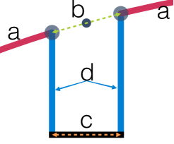
Our initial evaluation of laser-cutter templates showed that slotting joints, as used in cross-section models, are a common feature. Simply specifying the width of the slot as being of material thickness may have unwanted repercussions in the model as the overall length changes with thickness. In most cases, adapting the width of a slot should keep its position stable and therefore affects not only the width of the slot bottom, but also the length of the two path segments leading to and away from it (Figure 9a). If we increase the size of the slot in the example from Figure 9, the length of the blue segments needs to be adjusted as well. LaserSVG supports this through its calculation feature, but requires to transform several path commands into parametric variants.
Similar to the Tag selection option, the user can select the Tag slits option in the path editing panel (Figure LABEL:fig:path_Panel) This is again, a two-step function, which in the first step highlights all segments in the selected path that are the size of the specified material thickness. The designer can then delete the highlights that were erroneously considered to be slit bases.
First, we calculate the center point of the line connecting the two edge points of the slot (Figure 9b). The enclosing segments will be extended or shortened along this line. We then adjust the length of the bottom segment (Figure 9c) to fit the material thickness, and finally, adjust the length of the two parallel segments forming the slot (Figure 9d) if needed, i.e., the adjacent segments and the slit base are not parallel.
7. Evaluation
To evaluate our system, we tried to convert the designs of the 40 existing models from our random sample into LaserSVG templates. This post-hoc conversion is somewhat unusual as it requires a third person to dive into the geometric reasoning of the model. In a real-world scenario, the designer would do that while designing, or in a post-processing step of the template, making the task simpler.
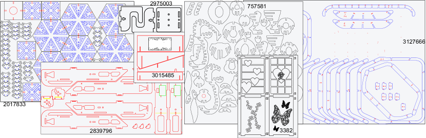
The effort necessary to convert an existing design highly depends on the quality of the file. The templates in our dataset come in a variety of file formats generated from various drawing programs. Even if the template author provides an SVG drawing, its quality highly depends on the origin of the file. Some files consist of single lines only, meaning they do not contain any coherent shape information. Others do not make use of primitives, but express every shape as path, although using the primitives would be simpler. The paths often contain a number of unnecessary nodes, leading to zero-length segments in the path, or the paths approximate curves using a large number of straight lines. Furthermore, Inkscape loads files with pixels as default unit, meaning that the values in the path descriptions do not correspond to the actual values in mm. If the author of the template did not specify the material thickness the design was made for, it is hard to determine wether the template already accounts for kerf. Some templates are not even consistent within their drawing, making the editing process unnecessary complicated (e.g., Thingiverse ID 757581). Therefore, most templates require some pre-processing to make the templates usable. This pre-processing includes decluttering of the file, conversion to mm, scaling to specified dimensions, and decluttering or joining of paths into meaningful units. This step is not directly related to the conversion into a LaserSVG template, but would be required in similar form for any modification of the given design and sometimes even for the mere use of the template. Depending on the export quality, it is sometimes simpler to redraw part of the design as, for example, dwg-files often only contain single lines which all have to be adjusted in case one wants to change something.
In the following we will discuss our observations
For very simple models with only mortise & tenon-joints, it is sufficient to specify the direction of the thickness adaptation and the anchor point for that change (cf. Thingiverse IDs 2913091, 4056240).
In many cases, the tenon is designed to match the material thickness to form a nicely closed surface (Thingiverse IDs 149, 23953, 124818, 1906241,2442411, 2839796, 2975003, 3016694, 3897974). which can easily be achieved by using the “Tag selection” functionality from our plug-in.
In enclosures for electronics, such as the popular cases for the RaspberryPi (27597,565828,566678), keeping the inside dimensions is crucial for the connectors to stay centered in their designated cutouts. For the outsides of the material to stay aligned, some edges have to be elongated. When editing the file manually, one would simply add a calculation such as {24+thickness}. For graphical editing, we present two solutions: One can simply add an additional node into the line which is exactly thickness away from the next one. This segment can then be tagged to be adjusted along with the remaining segments using the “Tag selection” tool. The second option is to compose the calculation through a graphical user-interface in the “Tag selected”-panel, by specifying the amount that has to be added.
The other common interconnection between plates are finger joints. If the inner dimensions of the enclosure are to be kept constant, the fingers can easily be tagged using the “Tag selection” tool (946265, 1169378, 2005219, 2281214, 3016694, 3140483, 3320769, 3419311). If the outer dimensions are to stay constant (9111, 2994225), we need to compensate for that by deepening the cuts between the fingers. For the edge formed by the ends of the fingers to remain at the same position, we need to subtract thickness from the edge leading to the finger joint. This can, again, be done manually or through the “Tag selected”-panel of the path editing plug-in.
Finally, slot-joints (4573, 24888, 25864, 59216, 1340543, 3015485) are a common way to interconnect pieces in planar section models (757581, 3127666, 3906772, or to create non-cubic enclosures (2017833).
These are the most complicated to parameterize, as not only the slot-base needs to be adjusted, but the edges left and right of the slot as well. We have added tool-support for this kind of connection (see Figure 9). Unfortunately, while this tools works in a number of cases (2017833, 3015485), it does not work satisfactorily in complex examples such as the rabbit (757581) or the basket (3127666).
8. Limitations
During the evaluation we encountered some situations which required workarounds in Inkscape or, in rare cases, manual calculations. In all cases, this was not a limitation by the LaserSVG library, but by the editing tools which we will improve based on these findings.
One interesting case was Thing no. 2442411, which looks simple, but it contains a stack of three layers of material with the two outer layers being held by mortises. This means that these two mortises not only have to be of material thickness, but also need to be spaced by the same amount. While it is easily possible to achieve this by adding a calculation to the initial move-command of the path, there is currently no tool support to specify this behavior graphically.
If mortises are not rectangular, but rounded rectangles defined as paths such as in thing 2281214, it is currently not possible to tag these automatically. As this is a limitation of the editing tool, it is possible to manually adjust the size of the straight segment between the rounded corners. The better solution is to define these as rectangles instead of paths, which then provides full support.
A possible workaround for the slot-joints in complex models is to use an approach demonstrated in thing 1340543, where instead of defining a closed path including the slots, one just draws the outline of the piece and overlays these with rectangles at the location of the slots. While the files are optically different, after cutting the design the result is identical.
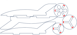
The rocket LaserSVG template embeds more advanced mathematical statements to properly use the material-thickness parameter in the tri-wing cutouts. These statements ensure the tri-wing cutouts are always centered in the circular pieces while changing parameters or scaling the model. We converted a simple rocket (Emlyon, 2017) template using relative path descriptions and the calculation features. The challenge are the non-orthogonal edges in the circular elements that need to be adjusted to the material thickness. We added and factors to the calculation, and adjusted the starting point of the tri-wing cutout by using a thickness-dependent offset to keep it centered within the circles. We implemented and embedded a JavaScript function to perform this calculation based on length and thickness directly in the template. The template attribute calls this function to adjust the initial move-command in the path description M{24-0.5*thickness}{32-triangleRadius(9,thickness)}. Calculating the center of rotation for the triangular shape makes this example quite complex. However, it shows the high ceiling that scripting in LaserSVG offers.
9. Conclusion & Future Work
In this paper, we presented LaserSVG , a fully SVG compliant file format to ease the process of adjusting vector models for laser cutting. LaserSVG files are self-contained and responsive and therefore allow end-users to make adjustments to the SVG model by simply opening the file in the web browser. As such, end-users are not required to install and use CAD modeling software: a web-browser suffices for updating the vector model, either interactively or automatically. We also contribute a LaserSVG editor to facilitate the process for designers to convert regular SVG files to LaserSVG templates. While LaserSVG is very powerful, our approach also has limitations which reveal several interesting challenges for future research.
First, ensuring vector drawings are always coherent when adjusting parameters can be complicated for advanced designs. For example, ensuring that intricate designs, such as the rocket (Figure 10) scales appropriately requires advanced mathematical statements. Similarly, supporting complex parametric joints along Bezier curves requires formulating the positions of all control points in relation to the material thickness. More research is needed on how to support designers in specifying complex mathematical statements and dependencies in vector drawings.
Second, although LaserSVG files are backwards compatible and can be rendered and adjusted with traditional SVG editors, making significant adjustments, such as adding control points to a path requires annotating the vector design again for conversion to LaserSVG. Designers also tend to make SVG designs starting from 3D models. Making changes to the 3D model and exporting them again will overwrite all LaserSVG annotations. In the future, we envision the adoption of the LaserSVG format in more design environments. This would also allow directly linking parameters of 3D solid models to LaserSVG parameters and integrate LaserSVG in the designers workflow without requiring additional conversions or annotations. Using a direct export also reduces the complexity of the SVG files, which, depending on how many conversion steps there have been, can become quite ill-formed.
Last, LaserSVG can be extended with additional parametric features, such as automatic adjustment of living hinges when using a different material thickness and interactive selection of different joints that are a better fit for changing kerf sizes.
References
- (1)
- Arvidsson and Gremyr (2008) Martin Arvidsson and Ida Gremyr. 2008. Principles of robust design methodology. Quality and Reliability Engineering International 24, 1 (2008), 23–35. https://doi.org/10.1002/qre.864 arXiv:https://onlinelibrary.wiley.com/doi/pdf/10.1002/qre.864
- Autodesk Fusion 360 (2019) Autodesk Fusion 360 2019. Integrated CAD, CAM, and CAE software. https://www.autodesk.com/products/fusion-360
- Baudisch and Mueller (2017) Patrick Baudisch and Stefanie Mueller. 2017. Personal Fabrication. Foundations and Trends in Human–Computer Interaction 10, 3–4 (2017). https://doi.org/10.1561/1100000055
- Baudisch et al. (2019) Patrick Baudisch, Arthur Silber, Yannis Kommana, Milan Gruner, Ludwig Wall, Kevin Reuss, Lukas Heilman, Robert Kovacs, Daniel Rechlitz, and Thijs Roumen. 2019. Kyub: A 3D Editor for Modeling Sturdy Laser-Cut Objects. In CHI ’19 (Glasgow, Scotland Uk). https://doi.org/10.1145/3290605.3300796
- Beyer et al. (2015) Dustin Beyer, Serafima Gurevich, Stefanie Mueller, Hsiang-Ting Chen, and Patrick Baudisch. 2015. Platener: Low-Fidelity Fabrication of 3D Objects by Substituting 3D Print with Laser-Cut Plates. In CHI ’15 (Seoul, Republic of Korea). https://doi.org/10.1145/2702123.2702225
- Dahlström et al. (2011a) Erik Dahlström, Patrick Dengler, Anthony Grasso, Chris Lilley, Cameron McCormack, Doug Schepers, and Jonathan Watt. 2011a. Scalable Vector Graphics (SVG) 1.1 Processing modes. https://www.w3.org/TR/SVG/conform.html#processing-modes
- Dahlström et al. (2011b) Erik Dahlström, Patrick Dengler, Anthony Grasso, Chris Lilley, Cameron McCormack, Doug Schepers, and Jonathan Watt. 2011b. Scalable Vector Graphics (SVG) 1.1 (Second Edition). https://www.w3.org/TR/SVG11/extend.html
- Emlyon (2017) Maker’s Lab Emlyon. 2017. Rocket Kit. https://www.thingiverse.com/thing:2440907.
- Festi (2013) Florian Festi. 2013. Python Module for Generating SVG Plots for Laser Cutting Boxes. https://github.com/florianfesti/boxes
- Gershenfeld (2017) Neil Gershenfeld. 2017. FabAcademy Final Project Presentations. http://archive.fabacademy.org/archives/2017/master/final_projects.html
- Heller et al. (2018) Florian Heller, Jan Thar, Dennis Lewandowski, Mirko Hartmann, Pierre Schoonbrood, Sophy Stönner, Simon Voelker, and Jan Borchers. 2018. CutCAD - An Open-source Tool to Design 3D Objects in 2D. In DIS ’18 (Hong Kong, China). https://doi.org/10.1145/3196709.3196800
- Hempel and Chugh (2016) Brian Hempel and Ravi Chugh. 2016. Semi-Automated SVG Programming via Direct Manipulation. In UIST ’16. https://doi.org/10.1145/2984511.2984575
- Hildebrand et al. (2012) Kristian Hildebrand, Bernd Bickel, and Marc Alexa. 2012. crdbrd: Shape Fabrication by Sliding Planar Slices. Computer Graphics Forum 31, 2pt3 (2012), 583–592. https://doi.org/10.1111/j.1467-8659.2012.03037.x
- Johnson et al. (2012) Gabe Johnson, Mark Gross, Ellen Yi-Luen Do, and Jason Hong. 2012. Sketch It, Make It: Sketching Precise Drawings for Laser Cutting. In CHI ’12 EA (Austin, Texas, USA). https://doi.org/10.1145/2212776.2212390
- Kato and Goto (2017) Jun Kato and Masataka Goto. 2017. F3.Js: A Parametric Design Tool for Physical Computing Devices for Both Interaction Designers and End-users. In DIS ’17. https://doi.org/10.1145/3064663.3064681
- Mahapatra et al. (2019) Chandan Mahapatra, Jonas Kjeldmand Jensen, Michael McQuaid, and Daniel Ashbrook. 2019. Barriers to End-User Designers of Augmented Fabrication. In CHI ’19 (Glasgow, UK). https://doi.org/10.1145/3290605.3300613
- MakerBot (2018) MakerBot. 2018. Customizer Developer Documentation. http://customizer.makerbot.com/docs
- Rhinoceros (2018) Rhinoceros 2018. 3D CAD Editing Tool. https://www.rhino3d.com
- Roumen et al. (2020) Thijs Roumen, Ingo Apel, Jotaro Shigeyma, Abdullah Muhammad, and Patrick Baudisch. 2020. Kerf-Canceling Mechanisms: Making Laser-Cut Mechanisms Operate Across Different Laser Cutters. In UIST ’20. https://doi.org/10.1145/3379337.3415895
- Roumen et al. (2019) Thijs Roumen, Jotaro Shigeyma, Julius Cosmo Romeo Rudolph, Felix Grzelka, and Patrick Baudisch. 2019. SpringFit: Joints and Mounts that Fabricate on Any Laser Cutter. In UIST ’19. https://doi.org/10.1145/3332165.3347930
- Schepers (2009) Doug Schepers. 2009. SVG Parameters 1.0, Part 1: Primer. http://www.w3.org/TR/SVGParamPrimer/
- Schwartzburg and Pauly (2013) Yuliy Schwartzburg and Mark Pauly. 2013. Fabrication-aware Design with Intersecting Planar Pieces. Computer Graphics Forum 32, 2pt3 (2013). https://doi.org/10.1111/cgf.12051
- Telezhinskyi (2018) Roman Telezhinskyi. 2018. Seamly2D - Open Source Pattern Design Software. https://seamly.net
- Wakkary et al. (2015) Ron Wakkary, Markus Lorenz Schilling, Matthew A Dalton, Sabrina Hauser, Audrey Desjardins, Xiao Zhang, and Henry W J Lin. 2015. Tutorial Authorship and Hybrid Designers: The Joy (and Frustration) of DIY Tutorials. In CHI ’15. https://doi.org/10.1145/2702123.2702550
- Weichel et al. (2013) Christian Weichel, Manfred Lau, and Hans Gellersen. 2013. Enclosed: A Component-centric Interface for Designing Prototype Enclosures. In TEI ’13. https://doi.org/10.1145/2460625.2460659
- Wiszniewski (2016) Tomek Wiszniewski. 2016. Parametric SVG. https://parametric-svg.js.org
- Yang et al. (2014) Yong-Liang Yang, Jun Wang, and Niloy J. Mitra. 2014. Mesh2Fab: Reforming Shapes for Material-specific Fabrication. CoRR abs/1411.3632 (2014). arXiv:1411.3632 http://arxiv.org/abs/1411.3632
- Yeh and Kim (2018) Tom Yeh and Jeeeun Kim. 2018. CraftML: 3D Modeling is Web Programming. In CHI ’18. https://doi.org/10.1145/3173574.3174101
- Yilbas (2001) B S Yilbas. 2001. Effect of process parameters on the kerf width during the laser cutting process. Proceedings of the Institution of Mechanical Engineers, Part B: Journal of Engineering Manufacture 215, 10 (2001), 1357–1365. https://doi.org/10.1243/0954405011519132
- Zheng et al. (2017) Clement Zheng, Ellen Yi-Luen Do, and Jim Budd. 2017. Joinery: Parametric Joint Generation for Laser Cut Assemblies. In C&C ’17. https://doi.org/10.1145/3059454.3059459