22email: enrico.virgilli@inaf.it 33institutetext: Hubert Halloin44institutetext: Université de Paris, CNRS, Astroparticule et Cosmologie, F-75013 Paris, France
44email: hubert.halloin@apc.in2p3.fr 55institutetext: Gerald Skinner66institutetext: University of Birmingham, Birmingham B15 2TT, UK
66email: gerald.k.skinner@gmail.com
Laue and Fresnel lenses
Abstract
The low-energy gamma-ray domain is an important window for the study of the high energy Universe. Here matter can be observed in extreme physical conditions and during powerful explosive events. However, observing gamma-rays from faint sources is extremely challenging with current instrumentation. With techniques used at present collecting more signal requires larger detectors, leading to an increase in instrumental background. For the leap in sensitivity that is required for future gamma-ray missions use must be made of flux concentrating telescopes. Fortunately, gamma-ray optics such as Laue or Fresnel lenses, based on diffraction, make this possible. Laue lenses work with moderate focal lengths (tens to a few hundreds of metres), but provide only rudimentary imaging capabilities. On the other hand, Fresnel lenses offer extremely good imaging, but with a very small field of view and a requirement for focal lengths 108 m. This chapter presents the basic concepts of these optics and describes their working principles, their main properties and some feasibility studies already conducted.
1 Introduction
The ‘low-energy’ gamma-ray band from keV to a few tens of MeV is of crucial importance in the understanding of many astrophysical processes. It is the band in which many astrophysical systems emit most of their energy. It also contains the majority of gamma-ray lines from the decay of radioactive nuclei associated with synthesis of the chemical elements and also the 511 keV line tracing the annihilation of positrons. However, observations at these energies are constrained in ways that those at lower and higher energies are not. At lower energies grazing incidence optics enable true focusing of the incoming radiation, forming images and concentrating power from compact sources onto a small detector area. At higher energies the pair production process allows the direction of the incoming photon to be deduced. But in the low energy gamma-ray band grazing incidence optics are impractical (the graze angles are extremely small) and the dominant Compton interaction process provides only limited directional information.
Detector background due to particle interactions and to photons from outside the region of interest is a major problem in gamma-ray astronomy. A large collecting area is essential because the fluxes are low, but unless a means is found to concentrate the radiation this implies a large detector and hence a lot of background. Shielding helps but it is imperfect and the materials in the shield themselves produce additional background. If the flux from a large collecting area can be concentrated with efficiency onto a small area of detector then for background-dominated observations there is an advantage in sensitivity of compared with a ‘direct-view’ instrument of area having the same background per unit area, energy band and observation time.
At energies where grazing incidence optics are not viable, only two technologies are available for concentrating gamma-rays. Both use diffraction. Laue lenses use diffraction from arrays of crystals while Fresnel lenses utilise diffraction from manufactured structures. Both type of lens can provide a high degree of concentration of flux from a compact on-axis source. Fresnel lenses provides true imaging, albeit with chromatic aberrations, whereas the Laue lens is a ‘single-reflection’ optic, where the off-axis aberrations are severe.
MeV astrophysics is now eagerly waiting for the launch of NASA’s COSI mission Tomsick2019 which is scheduled for 2025. This will be a survey mission with a large field of view - and consequently a relatively high background. Nevertheless, COSI is expected to be a factor of 10 more sensitive than Comptel the pioneering instrument for the MeV gamma-ray range shoenfelder93 . A focusing telescope using the techniques discussed here may improve the sensitivity for the study of individual sources by another large factor, allowing studies not possible with scanning, high-background, instruments.
Laue lenses and Fresnel lenses are discussed separately below.
2 Laue lenses
The concept of a Laue telescope is shown in Figure 1. The essential element is a ‘Laue Lens’ containing a large number of high-quality crystals.
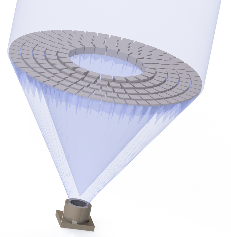
Each crystal must be correctly oriented to diffract radiation in a narrow spectral range from a distant source towards a detector located at a common focus behind the lens. The crystals are used in the Laue-mode (transmission) since the very small diffraction angles make it impractical to rely on surface reflections. Excellent reviews of previous work on this topic can be found in frontera10a and Smither2014 .
The term ‘Laue lens´ is actually a misnomer and it would be more correct to refer to a Laue-mirror. Such a ‘lens’ relies on the mirror reflection of gamma-rays from the lattice planes in the crystals. The reflective power of the electrons bound in atoms in a single lattice plane is very small, but the power increases with the square of the number of planes - or electrons - acting coherently.
2.1 Laue lenses basic principles: Bragg’s law
The requirement for coherent diffraction is both the strength and the weakness of Laue lenses. It provides for the possibility of high reflectivity, but at the same time it imposes a strict dependence of the diffraction angle, , on the wavelength, , (or the energy, ) of the radiation. This dependence is expressed by Bragg’s law:
| (1) |
where is the diffraction order, is the spacing of the crystal lattice planes and is the wavelength of the gamma-rays. The first order ( = 1) contributions are by far the most significant. For energies which concern us here the Bragg angles are always small , so we can set . In the following we shall often prefer to speak in terms of energy, , rather than wavelength. Bragg’s law then takes the form:
| (2) |
where is Planck’s constant and the velocity of light. ( (Å) (keV)).
From the Bragg equation for first diffraction order, with simple geometrical considerations it can be shown that there is a relation between the distance at which the crystal is positioned with respect to the Laue lens axis and the diffracted energy Ei:
| (3) |
where F is the focal length of the Laue lens.
Eq. 3 shows that for a given focal length, if crystals with a fixed are used, those placed closer to the lens axis are dedicated to the highest energies while those positioned further away from the axis diffract the lower energies. Consequently, at a given focal length there is a direct link between the energy band of a Laue lens and its spatial extent, rin to rout. For a narrow band Laue lens, with the whole surface optimised for a single energy, it would be necessary to arrange that varies in the radial direction such that is constant (an analogous condition will be seen when the zone widths of Fresnel lenses are discussed in section Fresnel Lenses).
2.2 Crystal diffraction
Ideal and mosaic crystals
Before going into details of the calculation of diffraction efficiencies it is useful to introduce a distinction between ‘ideal’ and ‘mosaic’ crystals. In ideal (defect free) crystals the crystalline pattern is continuous over macroscopic distances. Examples of such crystals are the highly perfect Silicon and Germanium crystals now commercially available thanks to their great commercial interest and the consequent intense development effort. ‘Mosaic crystals’ on the other hand are described by a very successful theoretical model introduced by Darwin darwin1914 ; darwin1922 a century ago. Darwin modelled imperfect crystals as composed of a large number of small ‘crystallite’ blocks, individually having a perfect crystal structure but slightly misaligned one to another. The spread of the deviations, , of the orientation of a lattice plane in one block from the mean for the entire mosaic crystal is described by means of a probability distribution , the so-called mosaic distribution function.
Darwin’s model has been very useful and quantitatively describes many aspects of real crystals. The mosaic distribution function, can be found experimentally for a given crystal through observation of the ‘rocking curve’, which is the measured reflectivity as function of angle for an incident beam of parallel, monochromatic gamma-rays when a crystal is scanned through the angle corresponding to a Bragg-reflection. The crystal sample should be thin enough that the reflectivity is never close to the saturation value. Examples of measured rocking curves are shown in Figure 2.
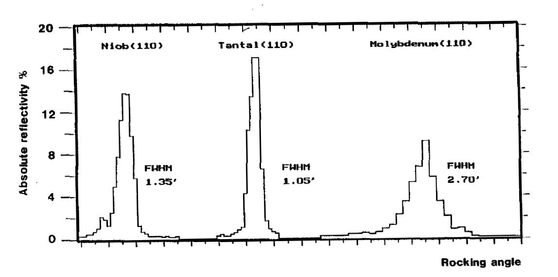
For good quality crystals the mosaic distribution can be well approximated by a Gaussian function. Its width, as observed through the rocking curve, is called the mosaic width of the crystal. Mosaic widths are specified as angular quantities, characterized by either the Full Width at Half Maximum (FWHM) or the standard deviation, , of the rocking curve.
Rocking curves are measured at constant diffraction angle, hence constant energy. For Laue lens design where the source direction is the fixed quantity, what is often of interest is the mosaic distribution as a function of the energy offset from the energy, , corresponding to the Bragg angle. If the standard deviation of the distribution as a function of energy is , then the two quantities are related by:
| (4) |
To be useful in a Laue telescope the rocking curve for each crystal should possess a single, narrow peak. Unless great care is taken in the growth of crystals the mosaic distribution may not be well behaved and the rocking curves may be broad or exhibit multi-peaked structures.
Diffraction efficiency
According to Schneider Schneider1981b the crystal reflectivity, , for mosaic crystals of macroscopic thickness in the Laue-case can be calculated from:
| (5) |
Here is the linear attenuation coefficient for photons of energy and is the crystal thickness. is the mosaic distribution as function of energy, and is the specific reflectivity (reflectivity per unit thickness). is defined as the energy where is at its maximum.
In the following we shall assume that the mosaic distribution has a Gaussian shape:
| (6) |
We then get for the peak reflectivity:
| (7) |
The value of the crystal thickness which maximizes the peak reflectivity is
| (8) |
with:
| (9) |
and the corresponding peak reflectivity is
| (10) |
Note that the specific reflectivity, R, and the attenuation coefficient, , are characteristic of a particular material and set of crystalline planes, whereas the mosaic width, , depends on the method of manufacture and subsequent treatment of the crystals. It is therefore reasonable to start by seeking crystals that maximise the value of and leave the choice of the mosaic width to the detailed lens design.
The specific reflectivity is given by:
| (11) |
with . Here is the classical electron radius, is the volume of the unit cell and is the ‘structure factor’ for the crystal unit cell. The structure factor depends on the crystal structure type (e.g. body centred cubic, face centred cubic), on the atoms, and on the choice of lattice planes involved, described by the Miller indices (h,k,l). The exponential factor describes the reduction in the diffraction intensity due to the thermal motion of the diffracting atoms. Considering only crystals of the pure elements, 11 can be rewritten as:
| (12) |
where is the atomic volume, is the interplanar distance of the diffracting planes, is the atomic form factor and is the diffraction order. Here use has been made of the approximations and .
The linear attenuation coefficient, , can be expressed as a function of the total atomic cross section, , and the atomic volume :
| (13) |
thus
| (14) |
Since at high energies both and are roughly proportional to it is clear that for gamma-ray energies a high atomic number and a small atomic volume (a high atomic density) are important for maximizing R/. For energies below keV photoelectric absorption may rule out the use of crystals of the heaviest elements for Laue lenses.
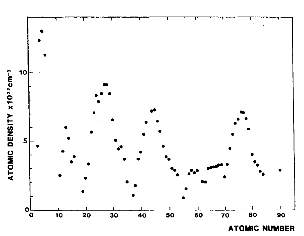
The atomic density of crystals of the pure elements varies systematically with the atomic number, , as illustrated in Figure 3. The most suitable elements for Laue lens crystals are found near the peaks in this plot, that is near (Al), (Ni, Cu,), (Mo, Ru, Rh Ag) or (Ta, W, Os, Ir, Pt, Au).
The atomic form factors are tabulated in the literature IntTblXCryst1977 and software for their calculation is publicly available XOP-paper .
The thermal factor, , turns out to be anti-correlated with the atomic density, thereby strengthening somewhat the case for a high atomic density Warren1969 .
Extinction effects
In the above derivation of the diffraction efficiencies only the attenuation by incoherent scattering processes was explicitly considered in equation 13. However losses due to coherent effects also occur. These are termed ‘extinction effects’ Chandrasekhar1960 . One type of extinction loss is due to the diffraction process itself and occurs in both mosaic and perfect crystals. Photons are removed from both the incoming beam and from the diffracted beam by diffraction. (The diffracted beam is a mirror image of the incoming beam with respect to the lattice planes and fulfills the Bragg condition just as well). This dynamic interaction is termed ‘secondary extinction’ and accounts for the factor in 5.
A more subtle extinction effect, which is only present if phase coherence is maintained through multiple diffractions, is termed the ‘primary extinction’. Every diffraction instance is associated with a phase shift of . Consequently, after two coherent diffraction processes the photon has accumulated a phase shift of and destructively interferes with the incoming beam. In the same way, three coherent diffraction processes will cause destructive interference in the diffracted beam. This effect only occurs in perfect crystals or in mosaic crystals in which the size of the crystallites is large enough that there is a significant probability of multiple successive coherent scatterings. The critical dimension here is the ‘extinction length’ (see zachariasen ) which can be estimated as:
| (15) |
The extinction length for the Cu(111) reflection at 412 keV is 66 m Schneider1981b . As is proportional to the energy it will be at the lower gamma-ray energies that extinction effects may become noticeable. For Laue lenses it is important to find or develop crystals in which the defect density is high enough to keep the crystallite size below at the lowest energies where the crystals are to be used.
2.3 Focusing elements
Classical perfect crystals
Perfect crystals, where the ideal lattice extends over macroscopic dimensions, are not particularly suitable for the use of Laue lenses in Astrophysics because they are too selective regarding the photon energy, even for Laue lenses intended for narrow line studies. Perfect crystals diffract with high efficiency, but only for an extremely narrow range of energy/angle combinations. For example, at 511 keV a perfect Germanium crystal will have an angular width of the diffraction peak (the ‘Darwin width’) of only 0.25 arc-seconds. This should be compared to the Bragg angle, which at this energy is 750 arc-seconds, i.e. about one part in 3000. The corresponding energy bandwidth is then only 0.14 keV! Thus, perfect crystals are not preferred for observations of astrophysical sources.
Classical mosaic crystals
Fortunately, perfect crystals are not the norm. Most artificial crystals grow as mosaic crystals. According to the Darwin model, such crystals can be viewed as an ensembles of perfect micro-crystals with some spread of their angular alignments. Photons of a specific energy may traverse hundreds of randomly oriented crystallites with little interaction and still be strongly diffracted by a single crystallite oriented correctly for this energy. Mosaic crystals generally perform much better than perfect crystals in the context of Laue lenses. The internal disorder, the mosaic width, may be controlled to some extent during the crystal growth or by subsequent treatment. Mosaic widths of some arc-minutes can be obtained with relative ease for a range of crystal types. For the lenses described below a mosaic width of about 0.5 arcminutes is typical. Such values can be obtained, but this has required substantial development effort courtois2005 . Copper crystals in particular have attracted interest because of the need for large size, high quality, Copper crystal for use in low energy neutron diffraction.
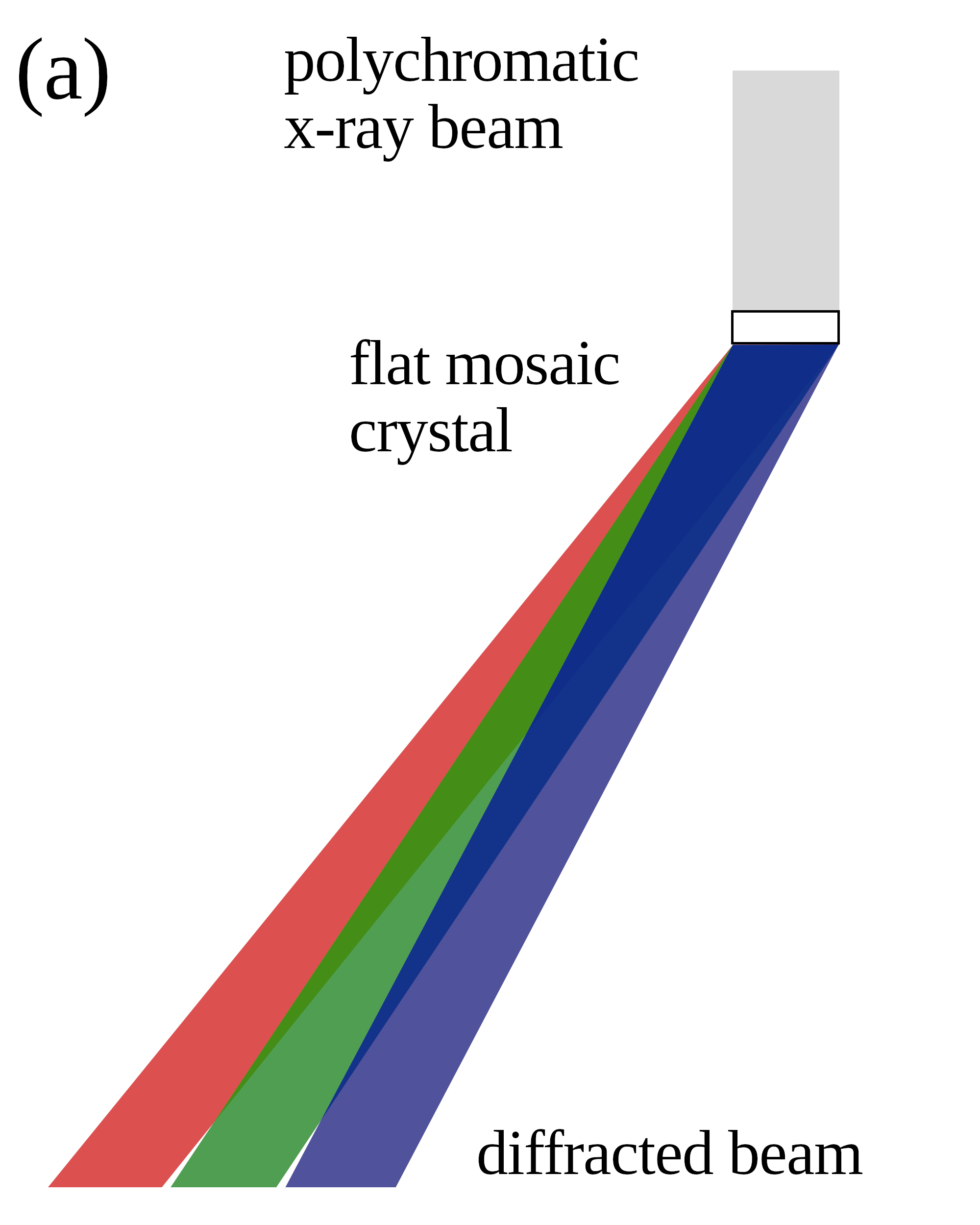
It must be kept in mind that Bragg’s law is always strictly valid, even for mosaic crystals. As illustrated in Figure 4-(a), after diffraction from a mosaic crystal a polychromatic beam of parallel gamma-rays with a spread of energies will emerge as a rainbow coloured fan. Its angular width will be twice the angular mosaic width of the crystal. Even if the crystal is oriented so that the central ray of the emerging beam hits the detector, the extreme rays of the fan may miss it.
At a given energy, the radiation diffracted from a flat mosaic crystal forms in the detector plane a projected image of the crystal. It is important to note that this projected image does not move if the crystal tilt is changed. Its position is fixed by Bragg’s law and it only changes in intensity.

Crystals with curved lattice planes
As well as perfect and mosaic crystals, a third group has attracted interest as potential diffractive elements for Laue lenses. These are perfect crystals with curved lattice planes. The curvature of the lattice planes has two remarkable effects: i) the secondary extinction may be suppressed and ii) the energy pass-band is not constrained anymore to the Darwin width but will be defined by the total range of lattice direction, i.e. in principle something under our control. If the lattice curvature is correctly chosen relative to the photon energy secondary extinction may be suppressed and the diffraction efficiency can approach 100 % - ignoring incoherent absorption, which is always present.
Different methods to create such lattice curvature have been proposed and experimentally demonstrated. One involves imposing a thermal gradient on the crystal along its thickness, such that the hot side expands and the cold side contracts. This method is very convenient in the laboratory because both the degree of bending (the bending radius) and the ‘sign’ of the bending can be changed with minimal change in the experimental set up smither05b . Unfortunately, this method cannot be used in space due to the significant power dissipation required to maintain the thermal gradient.
A second method relies on specific pairs of elements (or compounds) which can form perfect crystals across a range of component fractions. Stable, curved lattice planes exist in these binary crystals in the regions where a composition gradient is present Abrosimov05 . Silicon/Germanium composition-gradient crystals have been proposed for the ‘MAX’ Laue lens described in Section The MAX project (2006).
A further bending method relies on externally applied mechanical forces to bend the crystals. Mechanically bent crystals are used in several applications in laboratory experiments including monochromators. However the mass of the structures necessary to maintain the bending forces is unlikely to be acceptable for a space experiment.
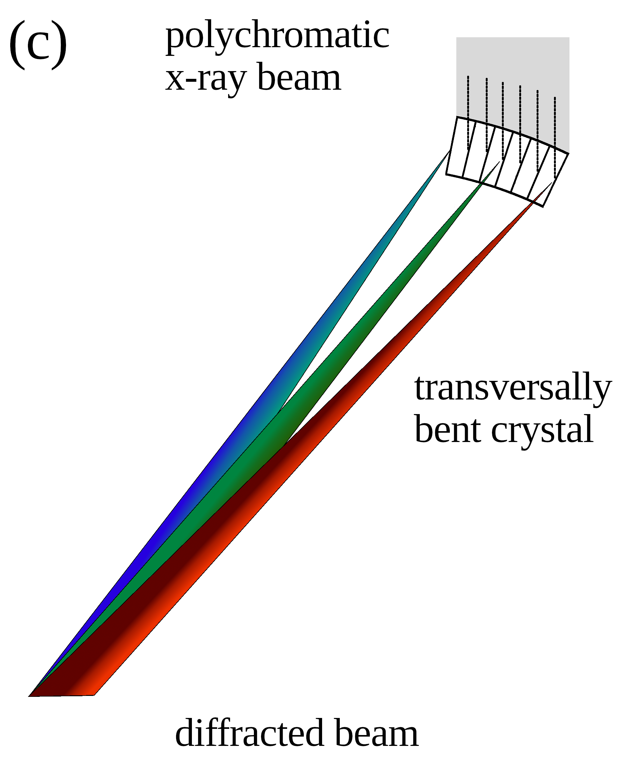
Controlled permanent bending of Silicon and Germanium wafers by surface scratching has been developed by the Institute of Materials for Electronics and Magnetism, (IMEM-CNR) in Parma Buffagni11 in connection with the Italian Laue project virgilli2014 . The lapping procedure introduces defects in a superficial layer of a few microns, providing a high compressive stress resulting in a convex surface on the worked side. In such transversally bent crystals the orientation of the diffraction planes with respect to the incident radiation continuously changes in the direction of the curvature of the crystal. If the bending radius is equal to twice the focal length of the lens, the effect is to produce achromatic focusing as illustrated in Figure 4.
A spectrum of finite extent may be focused into an area which is considerably smaller than the crystal cross-section. In this way the overall Point Source Response Function (PSF) of a Laue lens can be narrower than achievable with flat crystals of the same size.
Transversally bent crystals were studied in the Laue project in which a number of different aspects of the Laue lens technology were faced, from the production of suitable crystals to the definition of an accurate and fast method for their alignment. It was demonstrated through simulations and experimental tests virgilli13 that a transversally bent crystal focuses a fraction of the radiation arriving on its surface into an area which, depending on mosaicity, can be smaller than the cross section of the crystal itself. For some crystals and crystallographic orientations, if an external (primary) curvature is imposed through external forces a secondary curvature may arise. This effect is a result of crystalline anisotropy. It has been termed quasi-mosaicity ivanov05 and leads to an increased diffraction efficiency and angular acceptance camattari11 .
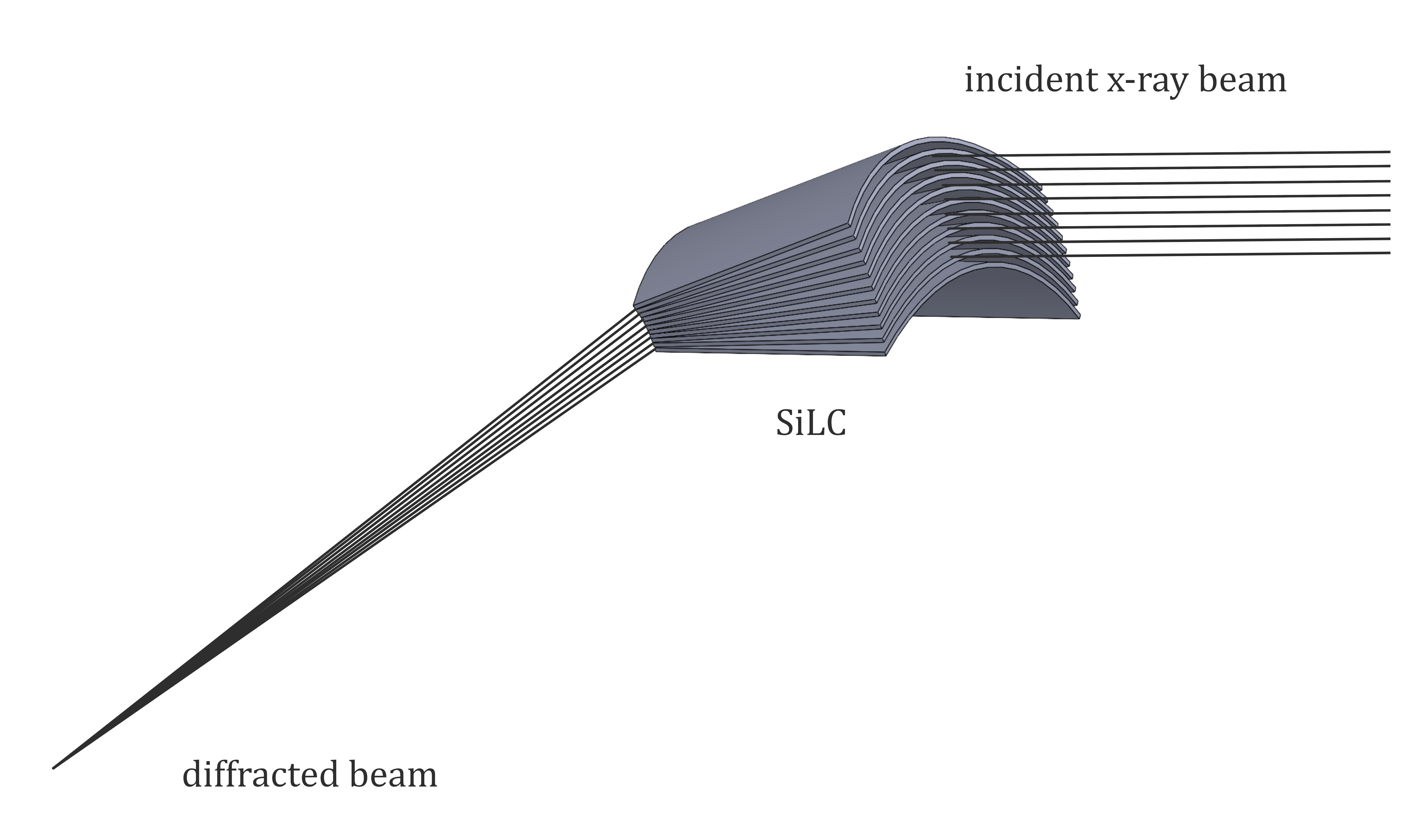
A promising manufacturing technology for bent crystals which may overcome some of the limitations of flat crystal diffraction optics is based on so-called Silicon Pore Optics (SPO) bavdaz2012 . This is a bonding technology for silicon wafers which is being developed for the ESA Athena mission. It has made possible the development of novel units for focusing gamma-rays called Silicon Laue Components (SiLCs ackermann13 ; girou17 ). These components are being developed at the Cosine company (The Netherlands) in collaboration with the University of California at Berkeley. They are self-standing Silicon diffracting elements which can focus in both the radial and the azimuthal directions. SiLCs consist of a stack of thin Silicon wafers with a small wedge angle between adjacent plates such that the diffracted rays from all the plates converge at a common focus. The incidence angle of the radiation is small so the radiation passes through only one plate. The wafer angle with respect to the optical axis of the telescope is selected such that the mean angle enables diffraction at energy , and the overall range of wedge angles between the wafers dictates the energy bandpass around the centroid . As can be seen in Figure 5 the curvature of the wafers allows focusing in the ortho-radial direction.
2.4 Laue lens optimization
The response of a Laue lens is strongly energy dependent. For a given focal length and crystal plane spacing the area diffracting a particular energy pass-band is inversely proportional to E. Furthermore, the diffraction efficiency of the crystals adopted for realizing these optics decreases with energy. These two reasons, combined with the fact that the gamma-ray emission of astrophysical sources typically decreases with energy according to a power law, make observations at high energies even more challenging. The dependence of the effective area on energy is a geometric effect and can be mitigated only at particular energies in narrow pass-band Laue lenses. The decrease in diffraction efficiency with energy can be mitigated by choosing crystals to maximize the reflectivity.
A number of parameters can be tuned in the optimization of a Laue lens. They are mainly related to the crystals properties (mosaicity, crystal material, diffraction planes, crystallite size, crystal thickness), or to the overall lens structure (lens diameter, focal length, inner and outer radius, geometrical configuration). The optimization is complex and depends on the Laue lens requirements (lens bandwidth, point spread function extension, total weight of the lens). The main factors involved in the optimization are described in the following sections.
Crystal selection
As discussed in Section Diffraction efficiency, crystals with high atomic density and high atomic number are generally preferable as Laue lens elements except at the lowest energies where photo-electric absorption may render their use less attractive. The technical difficulties involved in the fabrication and handling of crystals of the different chemical elements are also important factors. These difficulties vary significantly among the elements. The mechanical properties of the crystals are an important issue - for example Silicon and Germanium are quite hard and rugged whereas Copper, Silver and Gold crystals are soft and require special care in treatment and handling.
As already observed in Sect. Extinction effects, the crystallite thickness plays an important role in the reflectivity optimization. For given values of the mosaicity and crystal thickness, the highest reflectivity is obtained for a crystallite size much smaller than the extinction length of the radiation. At the energies of interest this thickness must be of the order of few m. The crystal mosaicity also has a primary role in the Laue lens optimization. The higher the mosaicity, the larger is the integrated reflectivity, and thus the effective area, but the broader is the signal on the focal plane detector. These two effects act in opposite senses in the optimization of the sensitivity.
The crystal thickness is also an important factor for the optimization of the crystal reflectivity and therefore for the maximization of the Laue lens sensitivity. Eq. 8 provides the thickness that maximizes the reflectivity for a given material and for fixed diffraction planes. As the best thickness is also a function of energy it is expected that, depending on the adopted geometry, crystals dedicated to high energy are thicker than those used to diffract low energies. It must be also taken into account that, the choice of the thickness maximizing the reflectivity would often lead to a mass unacceptable for a satellite-borne experiment. A trade-off between lens throughput and mass is then necessary.
Narrow- and broad-band Laue lenses
Depending on the scientific goal to be tackled, Laue lens can be designed, or adjusted, with two different optimizations: lenses for a broad energy pass-band (e.g. 100 keV - 1 MeV) or those configured to achieve
a high sensitivity over one or more limited range(s) of energy. The latter can be valuable for studying gamma-ray lines, or narrow band radiation. Relevant energies of interest might be the 511 keV e+/e- annihilation energy or the
800-900 keV energy range for its importance in Supernova emission.
The two classes of Laue lenses need different optimizations and
dispositions of the crystals over the available geometric area.
For a narrow energy pass-band Laue lens as many as possible of the crystals should be tuned to the same energy. According
to Eq. 3, the d-spacing
of the crystals should ideally increase in proportion to their radial distance from
the focal axis in order keep the diffracted energy fixed.
The energy range of a broadband Laue lens follows from Eq.
3. With the focal length and d-spacing of the
crystalline diffraction planes both fixed, the energy range will be from
where the radial extent of the lens is Rmin to Rmax. If the inner and outer radii are fixed, the simultaneous use of different materials, and thus of different dhkl, would allow enlarging the Laue lens energy pass-band compared with a single-material Laue lens. Equivalently, for given energy pass-band and focal length, the use of multi-material crystals would allow a more compact lens.
Tunable Laue lens
A classical Laue lens with fixed inner/outer radius and focal length has a pass-band which is uniquely defined by the d-spacing of the crystals used. The red curve in Figure 6 shows the effective area of an example 100 m focal length Laue lens configured to cover a 300 - 800 keV energy pass-band.
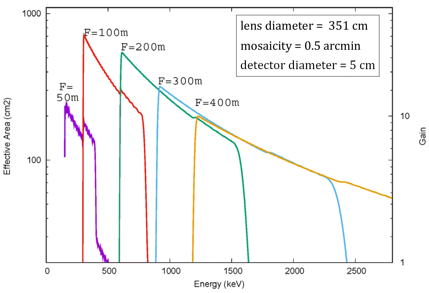
If all of the crystals could be retuned for different focal lengths, the Laue less could be made sensitive to different pass-bands. Furthermore, as shown in Figure 6, the larger the focal length, the broader the pass-band and the higher the integrated effective area. The adjustment in orbit is not trivial - both the orientation of thousands of crystals and the lens to detector separation must be changed and verified. The former requires thousands of actuators and a sophisticated optical system.
An innovative mechanism for the adjustment of the orientation of a crystal, along with an optical system for monitoring alignment of each one, has nevertheless been proposed lund2021a ; lund2021b . The mechanism is based on a miniature piezo-actuator coupled with a tilt pedestal and does not require power once a crystal has been correctly oriented. It is assumed that the lens and detector are on separate spacecraft that can be manoeuvred to adjust their separation.
Multiple layer Laue lenses
A possible way to increase the flux collection from a lens is to use two or more layers of crystals covering the same area. For instance, two layers of crystals can be used, one on each side of the lens structure. In order to focus at the same position, crystals placed at the same radius but in different layers must diffract at the same angle, so different crystals or Bragg planes must be used to diffract different energies.
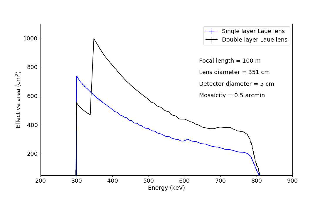
In a simulations lund2021a two layers of thin crystals made with Ag(111) and Ag(200), increased the effective area by about 65% (see Fig. 7). A third layer did not further increase the lens throughput. It must be stressed that with multiple layers, the diffracted radiation from any one layer will be attenuated by all of the other layers. The number of layers maximizing the effective area will depend on the crystals parameters (thickness, mosaicity, diffraction efficiency).
Flux concentration and imaging properties of Laue lenses
The sensitivity of a telescope using a Laue lens depends on the effective area over which flux is collected, but because observations will almost always be background limited it is also a function of the extent to which the collected flux is concentrated into a compact region in the detector plane.
For a given lens design the collecting area at a particular energy is just the sum of the areas of the crystals multiplied by their reflecting efficiency at that energy. Obviously only those crystals for which the incidence angle is close to the Bragg angle need be considered. In practice this means that the only crystals that contribute are those with centres that fall inside an annulus whose width depends on the extent, , of the rocking curve. For broadband lenses the incidence angle is a simple inverse function of radius from the axis. Consequently crystals at the centre of the band will contribute most, with the response decreasing towards the edges of the annulus. Making the small angle approximation , the width of the annulus is given by:
| (16) |
As the radius of the annulus is also proportional to this means that its area is proportional to .
Because each crystal simply changes the direction of the incoming parallel beam it will illuminate a region in the detector plane identical in size and shape to the profile it presents to the incoming radiation. This immediately means that the focal spot can never be smaller than the size of the crystals. Moreover, crystals that are not at the centre of the illuminating annulus will have a ‘footprint’ in the detector plane that is offset from the instrument axis by a corresponding distance. Thus to a good approximation the radial form of the on-axis PSF of a broadband Laue lens is the convolution of the (scaled) rocking curve and a flat-topped function corresponding to the crystal size111The azimuthal extent of the crystals has been ignored and it is assumed that the crystals are smoothly distributed in radius..
As is usual with telescopes, other things being equal, the best signal to noise ratio will be obtained with a compact PSF.
-
•
In circumstances where use of smaller crystals is feasible and would lead to a significantly narrower PSF then choosing them will always offer an advantage.
-
•
If the PSF width is dominated by the rocking curve width the situation is more complex. Decreasing the mosaicity will then narrow the PSF but also decrease the area of the diffracting annulus, reducing the advantage to be gained.
-
•
Lastly because of the dependence of the area of lens over which crystals diffract a given energy, a wider PSF can actually provide an advantage if it is the result of an increased focal length - although the signal will be spread over a detector area proportional to , the uncertainty due to background only increases as . This of course assumes that such a design is feasible given the cost and mass of the larger lens and detector.
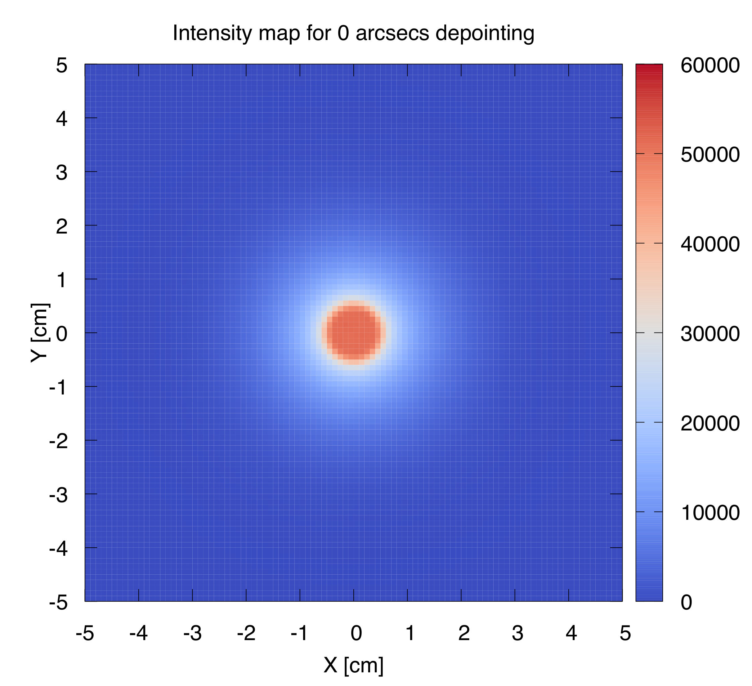
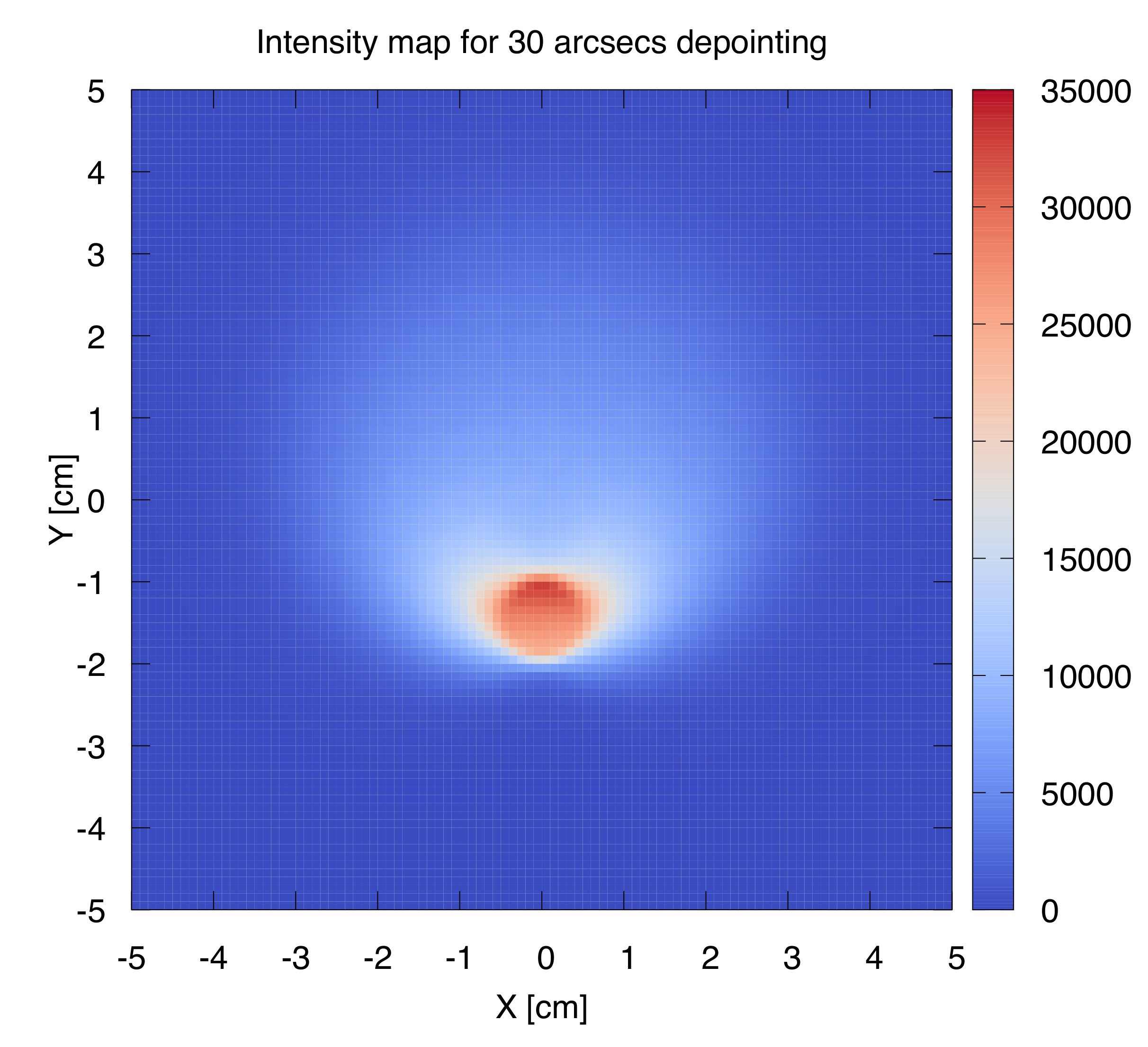
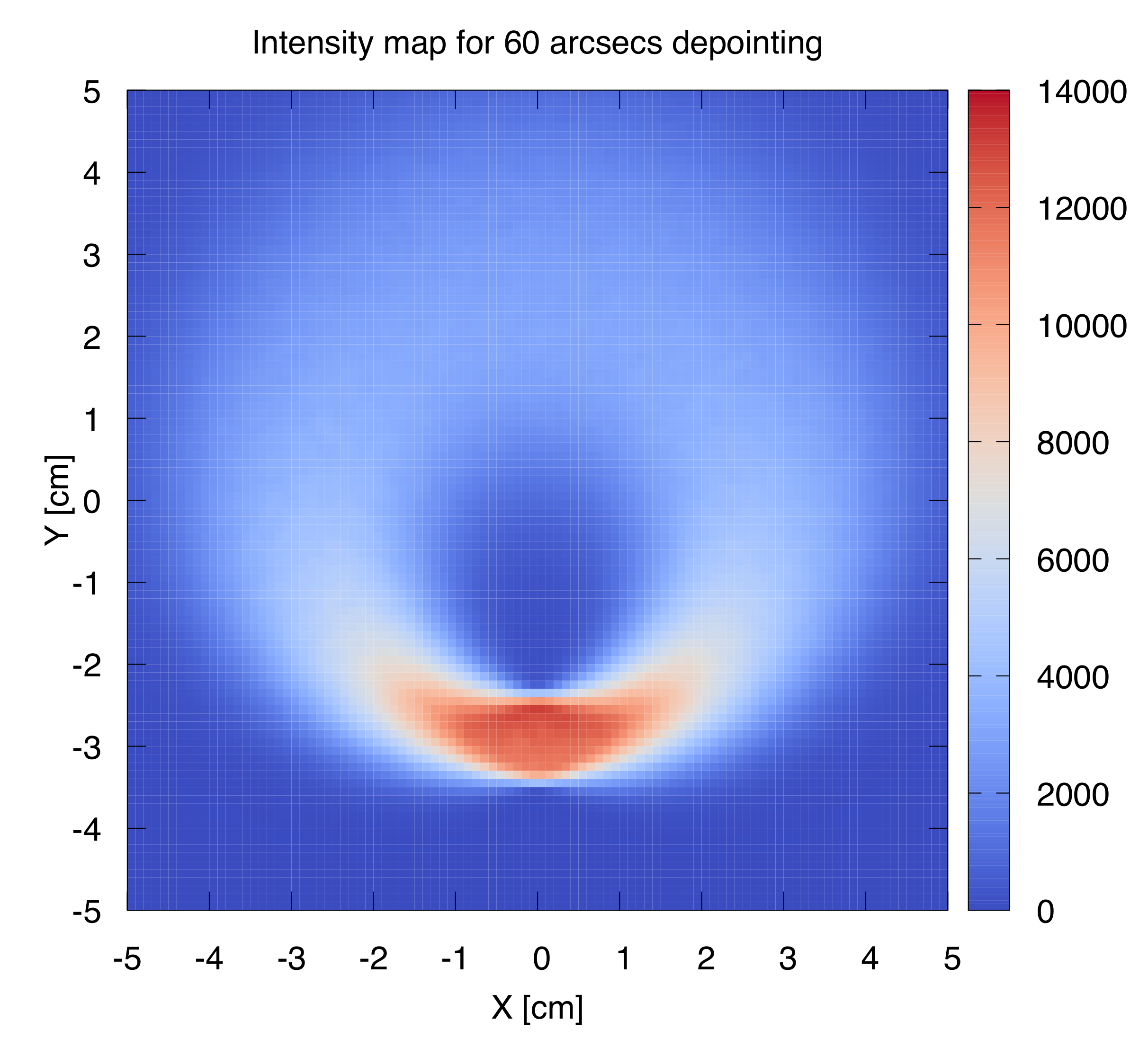
The above discussion concerns the response to an on-axis source. As Laue lenses are single reflection optics, they do not fulfill the Abbe sine condition and therefore for off-axis sources they are subject to coma. The aberrations are very severe as illustrated in Figure 8. The integrated flux is little affected by off-axis pointing, but importantly the image is smeared over a larger area and thus the signal-to-noise ratio of the signal is significantly reduced.
2.5 Technological challenges
The development of Laue lenses presents several technological challenges. These can be divided into two categories. The first is associated with the search for, and production of, suitable materials and components. Highly reproducible crystals with high reflectivity are needed, as are thin, rigid and low Z substrates and structures to minimize the absorption. The second category is related to the required accuracy of positioning and alignment, both for the mounting of the crystals in the Laue lens and for the alignment of the lens with respect to the focal plane detector. Some of the main issues that are being faced in studies and development of Laue lenses are described below.
I. Production of proper crystals and substrate
In order to cover a competitive geometric area a Laue lens must contain a large number of crystal tiles. The production of a large quantities of crystals having the optimal properties for providing a reflectivity that is as high as possible is still problematic. Crystal growth has been described as an art as well as a science. Advanced technologies present their own problems. For instance, it has been shown that bent crystals reduce the width of the PSF compared with flat crystals, but the advantages depend on very accurate control of the curvature.
II a. Crystal mounting methods and accuracy
In a Laue lens it obviously important that each crystal is properly oriented. It is useful to consider three angles describing the orientation of a generic crystal:
-
•
(i) a rotation about an axis parallel to the instrument axis. If there is an error in , diffraction will occur with the expected efficiency but the photons will arrive in the focal plane displaced by a distance , where is the distance of the crystal from the instrument axis. This displacement should be kept small compared with the spatial scale of the PSF.
-
•
(ii) a rotation about an axis normal to the diffracting crystal planes. To first order an error in will not have any effect on efficiency or imaging.
-
•
(iii) a rotation about an axis in the plane of the crystal plane and orthogonal to the instrument axis. If does not have the intended value then the energy at which the reflectivity is highest will change. For any given energy, the position in the focal plane where photons of a given energy are arrive will not be altered. However the number of photons diffracted by the crystal may either increase or decrease depending on the energy considered.
The probable effect is a spreading of the PSF as a result of enhancing the response of crystals that are not at the optimum radius for diffracting photons of a given energy towards the centre of the focal spot, at the expense of that of those that are. To avoid such spreading, errors in should be kept much smaller than the rocking curve width.
The most obvious mounting method is to use adhesives to bond the crystals to a supporting structure at their proper position and orientation. However due to glue deformation during the polymerization phases it has not proven easy to maintain the necessary precision 2014NIMPA.741...47B ; 2015SPIE.9603E..08V . The amount of misalignment that is introduced depends on the type of adhesive used and on the polymerization process (two components epoxy adhesive, UV curable, thermal polymerization, etc.).
In the CLAIRE experiment the effects of uncertainties in the bonding process were avoided by the use of a manual adjustment mechanism (Sect: The CLAIRE balloon project (2001)), but this technique is probably not appropriate for space instrumentation.
II b. Laue lens alignment
Because the MeV sky is poorly known at present, the issue of how to verify the correct alignment of gamma-ray diffraction instruments after launch and during operations is important.
It is therefore suggested that some optical means of verifying the shape of the large-scale structure of the lens should be incorporated from the start of the project. One possible way is to install mirror reflectors on the lens structure, the orientation of which can be monitored, perhaps from a separate detector spacecraft. If the attachment technique for these mirrors is similar to that used for the Laue crystals the long-term stability of the mirror alignment will also give some confidence in the stability of the crystal mounting.
2.6 Examples of Laue lens projects
In this section we will review the Laue lens experiments that have been realized or proposed from the early 2000s until the present. The CLAIRE project is the only Laue lens instrument that has actually flown. Other experiments have been realized in the laboratory as R&D projects and were directed to the advancement of well-defined aspects of the Laue lens technology (mainly crystal production and tiles alignment). Studies have been conducted of several possible space missions based on Laue lenses.
The CLAIRE balloon project (2001)
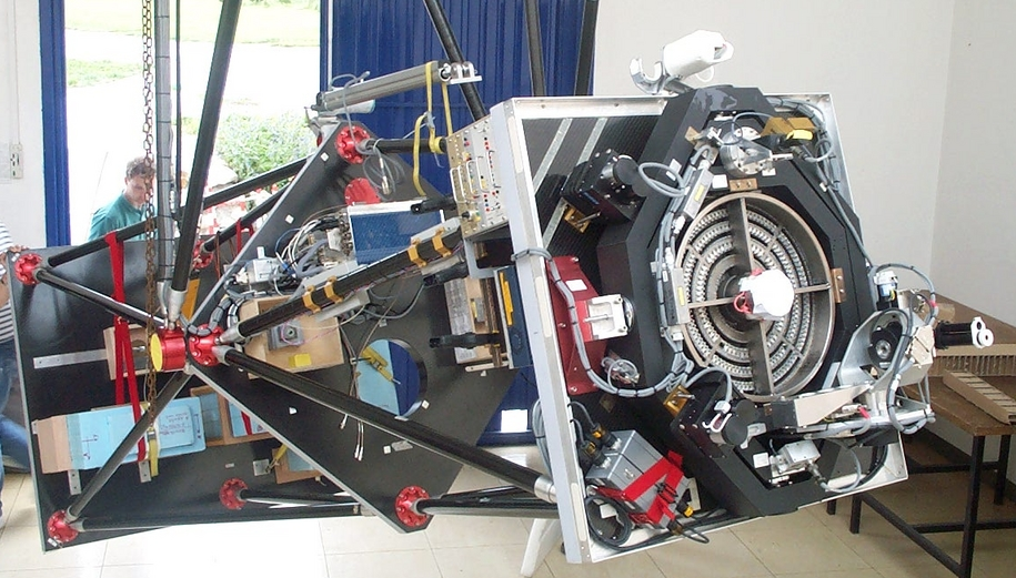
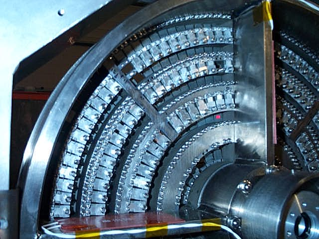
A pioneering proof-of-principle Laue telescope, CLAIRE, was built and successfully flown as a balloon payload by the Toulouse group in 2001 and 2002 laporte2000 ; halloin04 . The balloon payload is shown in Figure 9 during flight preparations.
The CLAIRE experiment is an example of a narrow energy pass-band instrument. It was designed for focusing photons with energy keV, with a pass-band of 4 keV at a focal distance of 2.8 m. The lens (Figure 10) consisted of 659 Germanium/Silicon mosaic crystals arranged in 8 concentric rings providing a collecting area of 511 cm2 and a field of view (fov) of 90 arcseconds. The mosaicity of the crystals selected was in the range 60 to 120 arc-seconds, leading to an angular resolution for the instrument of 25-30 arcseconds. Two crystal sizes were used: 10 10 mm2 and 7 10 mm2. The crystals focused the radiation onto a Germanium detector with 9 elements, each 15 15 40 mm3, having an equivalent volume for background noise of 18 cm3.
The fine tuning of the lens utilized a mechanical system capable of tilting each crystal tile until the correct diffracted energy was detected. The crystals were mounted via flexible lamellae on a rigid Titanium frame. The tuning of the individual crystals was done manually with adjustment screws. Due to the finite distance (14 m) of the X-ray source during the crystal tuning phase, the gamma-ray energy used was lowered from 170 keV to 122 keV. Moreover, also due to the finite source distance used for the crystals alignment, only a limited fraction of each crystal was effectively diffracting at the tuning energy, their subtended angle (about 150 arc-seconds, as seen from the source) being much larger that the crystal mosaicity.
The performance of the complete lens was verified using a powerful industrial X-ray source at a distance of 200 m, (hence a diffracted energy of 165.4 keV). Seen from a distance of 200 m each crystal subtended an angle of about 10 arc-seconds, i.e. significantly less than the crystal mosaic width.
The CLAIRE lens was flown twice on balloon campaigns in 2000 and 2001. In both flights the target source was the Crab Nebula. The observed diffracted signal at 170 keV was found to be consistent with that expected from the Crab Nebula given the lens peak efficiency, estimated at about 8% from ground measurements vonballmoos05 .
The MAX project (2006)
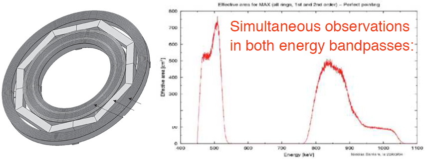
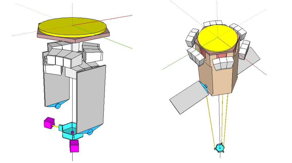
Following up on the successful CLAIRE project the French Space Agency, CNES, embarked on the study of a project, ‘MAX’, for a satellite mission with a Laue lens. MAX was planned as a medium-sized, formation-flying project with separate lens and detector spacecrafts launched together by a single launcher.
The scientific aims were (i) the study of supernovae type 1a (through observations of the gamma-lines at 812 and 847 keV), (ii) a search for localized sources of electron-positron annihilation radiation at 511 keV and (iii) a search for 478 keV line emission from 7Be-decay associated with novae. These objectives could be met by a Laue lens with two energy passbands: 460-530 keV and 800-900 keV. The left panel of Figure 11 shows the lens proposed for MAX which would contain nearly 8000 crystal tiles 15 15 mm2 with a mosaic spread of 30 arc-seconds. The total mass of the Laue crystals was expected to be 115 kg. A focal length of 86 m was foreseen. The predicted response of the MAX lens is shown in the right panel of Figure 11. In the end, however, CNES decided not to continue the development of MAX.
GRI: the Gamma-Ray Imager (2007)
The Gamma Ray Imager (GRI) mission concept was developed by an international consortium and proposed to the European Space Agency in response to the ‘Cosmic Vision 2015–2025’ plan. GRI consisted of two coaligned telescopes each with a focal length of 100 m: a hard X-ray multilayer telescope working from 20 keV up to 250 keV and a Laue lens with a broad passband 220 keV - 1.3 MeV. The low energy limit of the GRI Laue lens was driven by the anticipated upper limit of the multilayer technology. The NuSTAR mission has demonstrated the capability of multilayer telescopes of focusing photons up to 70-80 keV. Further developments are expected to allow multilayers to be used up to 200/300 keV.
The two optics were proposed to share a single solid state detector using CZT (Cadmium Zinc Telluride) crystals which are attractive as they can be used without cooling. Thanks to the 3-d capability of pixellated CZT, GRI could also be exploited for hard X-/soft gamma-ray polarimetry. Due to the long focal length, a two spacecraft, formation flying mission was proposed. With these features, GRI was expected to achieve 30 arcsec angular resolution with a field of view of 5 arcmin. Unfortunately, the mission was not selected by CNES or ESA for further assessment.
ASTENA: an Advanced Surveyor of Transient Events and Nuclear Astrophysics (2019)
Within the European AHEAD project (integrated Activities in the High Energy Astrophysics Domain) (natalucci18, ), a mission was conceived to address some of the current issues in high energy astrophysics: a high sensitivity survey of transient events and the exploitation of the potential of gamma-ray observations for Nuclear Astrophysics.
This mission concept, named ASTENA (Advanced Surveyor of Transient Events and Nuclear Astrophysics) (frontera19wp, ; guidorzi19wp, ) has been proposed to the European Space Agency in response to the call ”Voyage 2050”. It consists of a Wide Field Monitor, with both spectroscopic and imaging capabilities (WFM-IS), and a Narrow Field Telescope (NFT) based on a broad energy pass-band (60 - 700 keV) Laue lens with a field of view of about 4 arcmin and with an angular resolution of 30 arcsec. The Laue telescope exploits bent tiles of Si and Ge using the (111) reflecting planes. The tiles have dimensions of 30 10 mm2 in size (the longer dimension being in the focusing direction) and a bending curvature radius of 40 m. The focal length of the lens is 20 m. The crystals are arranged in 18 rings, with an outer diameter of 3 m that gives an outstanding geometric area of about 7 m2. The focal plane detector consists of 4 layers of CZT drift strip detectors (kuvvetli05, ) each layer having a cross section of 80 80 mm2 and thickness of 20 mm.
3 Fresnel Lenses
Fresnel lenses have been extensively discussed and studied for use in astronomy at X-ray energies (e.g. 1996SPIE.2805..224D ; 2004ApOpt..43.4845S ; 2004SPIE.5168..411G ; 2006ExA....21..101B ; 2008SPIE.7011E..0UG ; 2012ApOpt..51.4638B ; 2018ApOpt..57.1857B ) and missions exploiting them in that band have been proposed 2008SPIE.7011E..0TS ; 2012SoPh..279..573D ; 2020SPIE11444E..7VK . For a review see 2010XROI.2010E..16S . The circumstances in which such lenses offer diffraction limited resolution are discussed in 1.
Although the idea of Fresnel lenses for gamma-rays was introduced at least as far back as 2001 2001A&A...375..691S ; 2002A&A...383..352S . when their potential for micro-arc-second imaging was pointed out, the idea has rested largely dormant. It will be seen below that the main reason for this is the extremely long focal lengths of such lenses. A secondary reason is that although they offer effective areas far greater than any other technique, with a simple lens the bandwidth over which this is achieved is narrow because of chromatic aberration. However, if those difficulties can be overcome, gamma-ray Fresnel lenses offer some unique possibilities. Like Laue lenses, Fresnel lenses provide a way of concentrating incoming gamma-rays onto a small, and hence low background, detector. A gamma-ray Fresnel lens could focus the flux incident on an aperture that could be many square metres into a millimetre scale spot with close to 100% efficiency. Moreover, such a lens would also provide true imaging in the sense that there is a one-to-one correspondence between incident direction and positions in a focal plane. At photon energies above the limits of grazing energy optics no other technique can do this. Finally, the imaging can be diffraction-limited, which in the gamma-ray band with a metre scale aperture means sub-micro-arcsecond resolution. What is more, even if missions employing them present challenges, gamma-ray Fresnel lenses are, per se, low-technology items.
A conventional refractive lens, operating for example in the visible band, focuses radiation by introducing a radius-dependent delay such that radiation from different parts of the lens arrives at the focal spot with the same phase (Figure 13a). A Fresnel lens 222Strictly the term used should be “Phase Fresnel Lens” as the shorter form can also be used for stepped lenses in which coherence is not maintained between steps (Figure 13b) achieves the same phase-matching by taking advantage of the fact that the phase of the incoming radiation never needs to be changed by more than . Consequently the maximum thickness of the lens can be reduced to that necessary to produce a phase change of , a thickness termed here . It is usual to write the complex refractive index as where for gamma-rays both and are small and positive. The imaginary component describes absorption and does not affect the phase so where is the wavelength. The fact that is positive for gamma-rays means that a converging lens has a concave profile and a Fresnel lens has the form illustrated in Figure 13c. It is a more efficient form of a ‘Phase Zone Plate‘ (Figure 13d) in which the thickness profile has just two levels differing in phase shift by .
The parameter is given in terms of the atomic scattering factor discussed in Section Crystal diffraction by:
| (17) |
where is the classical electron radius and is the atomic density. For lenses of the type considered here is essentially zero. Well above all absorption edges approaches the atomic number and so is constant. Thus is proportional to or inversely proportional to the square of the photon energy .
In principle in the region of the 1.022 MeV threshold for pair production in the nuclear electric field and above, Delbrück scattering should be taken into consideration. Early reports of an unexpectedly large contribution to from this effect 2012PhRvL.108r4802H turned out to be mistaken 2017PhRvL.118p9904H but did lead to experimental confirmations of predicted gamma-ray refractive indices at energies up to 2 MeV 2017PhRvA..95e3864G ; 2017PhLA..381.3129K . Like those from Delbrück scattering, contributions from nuclear resonant scattering will also be negligible in most circumstances.
Although is extremely small at gamma-ray energies, the wavelength is also extremely short, for example 1.24 pico-metres at 1 MeV. Using from Eq. 17 results in the following expression for in terms of some example parameters
| (18) |
Noting that for materials of interest is in the range 0.4 to 0.5, this means that a gamma-ray Fresnel lens need have a thickness only of the order of millimetres.
The period of the sawtooth profile where it is lowest at the edge of the lens is a crucial parameter. Again in terms of example parameters, for a lens of diameter and focal length the minimum period is given by
| (19) |
The difficulties lie in the term. For reasonable values of extremely long focal lengths are required.
is an important parameter in another respect. The PSF will be an Airy function with a FWHM of , so the focal spot size using this measure will be given by
| (20) |
That is to say the size of the focal spot is about half the period at the periphery of the lens. The corresponding angular resolution is and is given in micro-arcseconds () by
| (21) |
Thus gamma-ray Fresnel lenses have the potential to form images with an angular resolution better than available in any other waveband and would be capable of resolving, for example, structures on the scale of the event horizons of extra-galactic massive black holes.
3.1 Construction
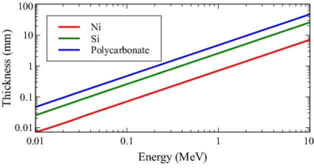
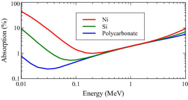
If the full potential of a Fresnel lens is to be realised, then Eq. 20 implies that should be larger than the detector spatial resolution and so should be of the order of millimetres or more. Except at energies above 1 MeV the required thickness is also of the order of millimetres (Fig. 14a) so high aspect ratios are not then needed. Almost any convenient material can be used – the nuclei only serve to hold in place the cloud of electrons that produces the phase shifts! Dense materials have the advantage of minimising thickness but also tend to be of higher and hence more lossy at low and high energies. Over much of the gamma-ray band all reasonably low materials have similarly low losses (Figure 14b). Because the refractive index is so close to unity, dimensional tolerances are relatively slack. Using the Maréchal formula 1982JOSA...72.1258M , if the rms errors in the profile are kept within 3.5% of the maximum lens thickness (assumed to be ) the loss in Strehl ratio (on-axis intensity) will be less than 5%. If the lens is assembled from segments then the precision needed in their alignment is only at a similar level. Thus a range of constructional technologies can be considered, including diamond point turning, vapour-phase deposition, photo-chemical etching and 3-d printing.
3.2 The focal length problem
As argued above, if the the best possible angular resolution is sought then detector consideration drive one to a . When this is coupled with a requirement for a reasonable collecting area Eq. 19 implies a focal length of the order of km. This sort of focal length clearly demands formation flying of two spacecraft, one carrying the lens and the other a focal plane detector. Minimising station-keeping propulsion requirement suggests locations near to a Sun-Earth Lagrangian point.
The line of sight from detector to lens must be controlled with sufficient accuracy to keep the image on the detector, so the precision needed depends on the size of the detector. This could be from a few cm up to perhaps 1m. Changes in the direction of that line of sight need to be determined with an accuracy corresponding to the angular resolution aimed for, which could be sub-micro-arcsecond.
Detailed studies have been performed of missions with requirements that meet all of these requirements separately. Not all are met together in any single study, but on the other hand the complexity of the instrumentation and spacecraft was in each case much greater than that for a gamma-ray Fresnel telescope. New Worlds Observer requires a 50 m star shade and a 4 m visible-light diffraction-limited telescope to be separated by km 2009SPIE.7436E..06C . The transverse position of the telescope must be maintained to within a few cm. The MAXIM X-ray interferometer mission calls for a fleet of 26 spacecraft distributed over an area 1 km in diameter to be separated from a detector craft km away 2003ExA....16...91C ; 2005AdSpR..35..122C . The requirement for a diffraction-limited gamma-ray Fresnel lens mission to track changes in the orientation of the configuration in inertial space at the sub-micro-arcsecond level are similar to the corresponding requirement for MAXIM, though only two spacecraft are needed. MAXIM studies envisaged a ‘super star tracker’. Such a device could locate a beacon on the lens spacecraft relative to a stellar reference frame. In terms of separation distance, the requirement for km separation can be compared with the needs of the LISA gravitational wave mission 2021AdSpR..67.3868J for which 3 spacecraft must each be separated from the others by km, though in this case it is the rate of change of inter-spacecraft distance that requires strict monitoring rather than the orientation.
3.3 Effective area
The focusing efficiency of a gamma-ray Fresnel lens will depend on the fraction of incoming radiation that passes unabsorbed through the lens and on the efficiency with which that radiation is concentrated into a focal spot.
In Figure 14b the mean transmission of a lens with a maximum thickness of and a typical profile is shown for some example materials. Transmissions in excess of 95% should generally be possible. For an Airy disc 84% of the radiation falls within the central peak, that is to say within a radius equal to the resolution according to the Rayleigh criterion. As noted in Section Construction, allowing for profile errors with an rms level of 3.5% rms of the maximum height could reduce the Strehl ratio by 5%. If the errors are random, the form of the PSF will be little changed and so the effective area will be reduced in proportion. Combining all these factors together indicates a focussing efficiency of about 75%.
We take as a reference design a 2 m diameter lens made from polycarbonate with a nominal working energy of 500 keV and focal length km. The baseline active thickness is taken to be mm but absorption in a 2 mm substrate has been allowed for. Additional support against diaphragm mode vibrations would obviously be needed during launch but out of plane distortions during operation have little effect.
Allowing for the above factors, an effective area over 20000 cm2 should be attainable with a simple Fresnel lens having these parameters. The diffraction-limited angular resolution of such a lens would be 0.31 micro-arc-seconds.
3.4 Chromatic aberration
Unfortunately the above indication of a possible effective area applies only at the particular energy and focal distance for which the lens has been designed. An important limit to the performance of a Fresnel lens is the chromatic nature of the imaging. The bandwidth over which the good focussing is achieved is very narrow. For even quite small deviations from the wavelength for which the profile has been designed the focal length changes and for a fixed detector position the focal spot rapidly becomes blurred. The FWHM of the on-axis intensity as a function of energy is approximately
| (22) |
where is the Fresnel number, . When the lens thickness is then is equal to twice the number of rings.
If the flux within a focal spot the size of the ideal Airy peak is used as a measure of the response, then the bandwidth is somewhat larger, with the numerical factor in Eq. 22 increased to about 2.95, and if the flux from a larger detector region is accepted, then the bandwidth increases further as seen in Figure 15. The improvement will be at the expense of poorer angular resolution and increased detector background. Note that the diffraction-limited angular resolution will anyway only be available if the detector energy resolution is good enough to select only those photons within . For a High Purity Germanium detector (see Volume 2 of this work, 2 ) then at 500 keV, effectively setting a limit of about 700 on the useful Fresnel Number of a diffraction limited telescope using a simple gamma-ray Fresnel lens.
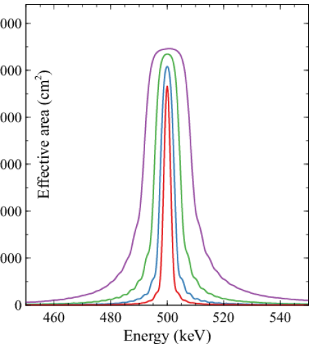
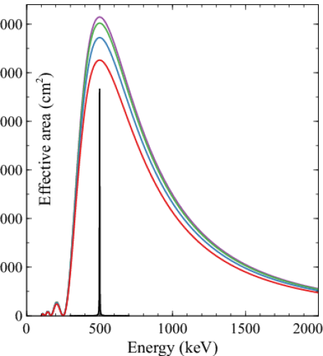
Over a much wider band, good focussing can be recovered by adjusting the detector position (Figure 15) but only radiation within the narrow bands can be focussed efficiently for any given position. There is a direct analogy with the tunable Laue lenses described in Tunable Laue lens, but for a Fresnel lens no adjustment is required to the lens, only a change in focal distance.
For visible and IR radiation it has been shown possible to increase the bandpass of Fresnel lenses by correcting the chromaticity of one diffractive lens with that of another one of opposite power, but such systems cannot produce a real image as is required for a gamma-ray telescope 1976ApOpt..15..542B ; 2010XROI.2010E..16S . Similarly schemes used in those wavebands to make ”Multiorder” or ”Harmonic” Fresnel lenses by increasing the maximum thickness of the lens so that it becomes a (different) integer multiple of at each wavelength 1995ApOpt..34.2462F ; 1995ApOpt..34.2469S do not work in the gamma-ray band. A small part of the surface of such a lens can be regarded as a diffraction grating blazed to direct radiation into the appropriate order, but as for gamma-rays is almost universally proportional to , the blaze angle cannot be correct at different energies.
However various possibilities do exist for alleviating the chromaticity problem:
-
1.
‘Axilenses’ in which the pitch is varied in ways other than the variation of a regular Fresnel lens. This can produce an enlarged bandwidth at the expense of efficiency 2009SPIE.7437E..0JS . The integral over energy of the effective area is close to that of a corresponding classical Fresnel lens.
-
2.
Achromatic doublets. While the focal length of a diffractive lens for X-rays or gamma-rays is proportional to , that of a refractive lens is even more strongly dependent on energy, being proportional to . In various contexts 2002A&A...383..352S ; 2003SPIE.4851..599G ; 2003Natur.424...50W it has been pointed out that consequently diffractive and refractive lenses for which the focal lengths are
(23) can be combined to form an achromatic doublet for which the combined focal length is to first order independent of wavelength. In the gamma-ray band the absorption losses for a full refractive lens with useful parameters are likely to be prohibitive but steps that are many times can be introduced. This leads to a lens having a profile corresponding to the combination of those shown in Figure 16(a) and (b). Fig 16(c) is a zoom on parts of the fine structure in the diffractive component, (b). At a given radius only the total thickness is important, so the two components can be separate as shown, or back to back in s single component, or the diffractive profile can be superimposed on that of the refractive one. With such lens focusing then be achieved at a number of wavelengths over an extended band (Figure 17(a)). The peak effective area is less than that for a single lens but the integral can be several times higher. The mass of the lens will be many times that of a simple lens and the finest scale of the structure must be a factor of two smaller.
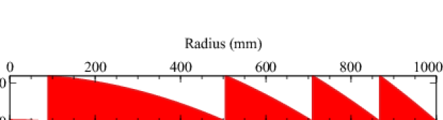
Figure 16: Profile of an achromatic doublet. (a) The refractive component (b) The diffractive component (Fresnel lens) component (c) Zooms on sample regions of (b). 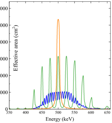
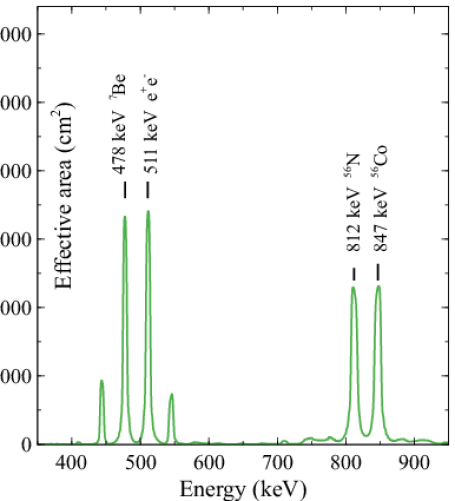
Figure 17: (a) The effective area of ‘achromatic’ doublets in which a simple converging Fresnel diffractive lens is combined with a diverging refractive one. The refractive component is assumed to be stepped at points where the thickness would exceed either 20 (green) or 80 (blue) times at the nominal energy of 500 keV. The flux is assumed to be collected from a spot 4 times the diameter of the central peak of a diffraction limited response. The corresponding curve from Figure 15 is reproduced (red line) for comparison. (b) The corresponding effective area for a multiwavelength lens optimised for response at 4 energies of astrophysical interest. -
3.
Multi-wavelength lenses. Recently, a number of papers have been published describing the design of ‘achromatic diffractive lenses’ for UV/visible/IR radiation (e.g. BanerjiSWIR ). The approach used is to optimise the thickness of a number of concentric rings so that the imaging performance over a number of wavelengths is as good as possible based of some figure of merit. The same technique can be used to design gamma-ray lenses. At first sight the reported performance of the IR lens designs is remarkably good with, for example, 91% ‘average efficiency’ reported over wavelengths spanning a factor of 2. On detailed examination, though, the efficiency is low except at a few specific wavelengths for which the design was optimised and analysis suggests that even at these wavelengths the efficiency may have been overestimated 2021Optic...8..834E .
If the maximum thickness is restricted to be then the integrated effective area of a lens designed in this way is found to be similar to that of a simple Fresnel lens. If larger thicknesses are allowed then the performance and limitations are similar to those for an achromat of the same total thickness but there is the possibility of choosing the energies at which the performance is optimised. An example is illustrated in Figure 17 (b) which shows the effective area of a lens designed to work simultaneously at the energies of 4 astrophysical gamma-ray lines. The approach used is basically that described by Doskolovich et al. 2020OExpr..2811705D which maximises the Strehl ratio averaged over the design energies. However an additional step was performed in which different target phases were tried and that selected which resulted in the highest value for the minimum over the four energies of the effective area, thus avoiding solutions in which one dominated.
Table 1: Parameters of example lens designs. All the designs have the following in common - Nominal energy: 500 keV, Diameter: 2 m, Focal distance: km, Fresnel Number: 400, Diffraction limited angular resolution 0.3 micro-arc-seconds, Material: Polycarbonate. A substrate of 2 mm is allowed for in the mass and in calculating the effective area but not included in the ’active thickness’. The effective areas quoted are those for the lens and do not include detector efficiency. Those quoted here assume that the flux is collected from a 12 mm diameter region in the image plane. rms figure errors of 3.5% of have been allowed for. Type Figure Active thickness Mass Effective Area mm kg Peak (cm2) Integral ( cm2 MeV ) Simple Fresnel 15a 2.4 1 12 26735 331 Achromatic Doublet 17a(i) 50 21 100 15768 720 ” 17a(ii) 191 81 332 5224 440 Multiwavelength 17b 24 10 52 17064 642
4 Detector issues for focused gamma-rays
A discussion of detectors for gamma-ray astronomy can be found in Volume 2 of this work. Here we present some specific considerations for detectors for focusing gamma-ray telescopes.
-
•
Low Background. Gamma-ray observations are almost always limited by background from diffuse sky emission and events arising directly or indirectly from cosmic-rays. It is imperative to suppress these as far as possible. Shielding is heavy and even active shielding is imperfect, some background actually being created by the shielding itself.
-
•
Sensitivity to Photon Arrival Direction. A key method of background reduction in the low energy gamma-ray band involves extracting information about the direction from which a photon arrived. Where the first interaction of a photon in the detector is a Compton scattering and the 3-d locations of that and subsequent interactions can be recorded a Compton kinematics analysis allows constraints to be placed on the arrival direction. Although there are ambiguities and in the MeV range the precision is limited to a few degrees, background can be drastically reduced by selecting only events whose direction is consistent with having passed through the lens. Obviously such analysis is not possible for all events, but it is possible to identify a subset of low detection efficiency, very low background, events and give these a high weight during analysis.
-
•
Position Resolution. In an imaging system it is strictly the position where a photon first interacts in the detector that is important, though the location of the centroid of all energy deposits may provide an adequate approximation. Even when the instrument is used as a flux-collector the position information can be used to define a region of the detector within which events are counted or, better, to attribute to each event a weight depending on the noise level and the expected response at its location. The latter amounts to ’PSF fitting’. Of course Compton kinematics analysis requires recording the positions in 3-d of subsequent interactions as well as the first.
-
•
Spatial extent For a Laue lens a large detector will allow all of the events in the broad wings of the PSF to be captured. With the long focal lengths associated with Fresnel lenses, fields of view tend to be very small and are limited by how large a detector is feasible. In either case a large detector can provide regions that can be used for contemporaneous background estimation, obviating or reducing the need for ’off-source’ observations
-
•
Energy Resolution. As gamma-ray lenses operate over a limited band, good energy resolution reduces the amount of background accompanying the signal. Fresnel lenses, particularly those that are large or have less extreme focal lengths, suffer from severe chromatic aberration so this is crucial where they are used. More generally, insufficient energy resolution will degrade the angular resolution of the Compton kinematic reconstruction and so increase the background.
-
•
Detection efficiency Detection efficiency is a major problem in the MeV region. The photons are very penetrating and a non-negligible fraction of photons traverse the detector without interacting at all.
The constraints resulting from these objectives are often conflicting. A dense detector is desirable to maximise efficiency, but for Compton reconstruction low density materials are favoured. Compton reconstruction requires measuring position and the energy deposits at multiple sites but on the other hand electronic read-out noise has least impact on energy resolution if all of the charge is fed to a single preamplifier.
High purity Germanium detectors provide good efficiency and currently the best energy resolution. Germanium based Compton cameras are well advanced and demonstrated Tomsick2019 . Cadmium-Zinc-Telluride (CZT) elements have an energy resolution that is only slightly inferior, do not need cooling and can be assembled in large arrays. More complex detectors using a 3d-imaging Silicon scattering column surrounded by a 3d-imaging CZT-shield absorbing the scattered photons may reach a higher efficiency, but are currently at a development stage kuvvetli05 .
5 Conclusions
Diffractive gamma-ray optics is a field yet to be explored and exploited. Nevertheless, Laue and Fresnel lenses offer unique possibilities. The examples shown in this review illustrate both their capabilities and their limitations. An important consideration in choosing a lens design is the expected signal and how it compares with the likely event rate due to background in the detector. Increasing the effective area is not necessarily an advantage if the background noise increases. For photon-starved observations of continuum sources, though, large integrated effective areas are needed. For applications in which lower effective area or poorer resolution are adequate, reduced diameter or shorter focal lengths can be considered. In some cases an array of smaller lenses can provide the best solution.
Observational MeV astrophysics is still in its infancy. We only know of a handful of low energy gamma-ray point sources. This is even less than the number known at 100 MeV and above from the SAS-2 and COS-B missions in the 1970s and 1980s. Today high energy gamma-ray sources are counted in the thousands. For MeV astrophysics we now await results from the COSI mission tomsick19 , which in a few years will give us a much clearer picture of the sky at a few MeV, that will be very important in designing future gamma-ray telescopes.
6 Cross References
-
1.
Willingale, Richard. Handbook of X-ray and Gamma-ray Astrophysics, Volume 1: X-ray Experimental Techniques and Missions, “Diffraction-limited optics and techniques”
-
2.
TBD, Handbook of X-ray and Gamma-ray Astrophysics, Volume 2: Gamma-ray Experimental Techniques, Observatories, and Missions, “Germanium detectors for gamma-ray astronomy”
References
- (1) J. Tomsick and et al, The Compton Spectrometer and Imager, in Astro2020 APC White Paper, Vol. Astro2020 APC White Paper, pp. 1–11 (2019).
- (2) V. Schoenfelder, H. Aarts, K. Bennett, H. de Boer, J. Clear, W. Collmar, A. Connors, A. Deerenberg, R. Diehl, A. von Dordrecht, J. W. den Herder, W. Hermsen, M. Kippen, L. Kuiper, G. Lichti, J. Lockwood, J. Macri, M. McConnell, D. Morris, R. Much, J. Ryan, G. Simpson, M. Snelling, G. Stacy, H. Steinle, A. Strong, B. N. Swanenburg, B. Taylor, C. de Vries and C. Winkler, Instrument Description and Performance of the Imaging Gamma-Ray Telescope COMPTEL aboard the Compton Gamma-Ray Observatory, apjs 86, p. 657 (1993), doi:10.1086/191794.
- (3) F. Frontera and P. Von Ballmoos, Laue gamma-ray lenses for space astrophysics: status and prospects, Special Issue - X-Ray Focusing: Techniques and Applications (2010), doi:ar:1007.4308v3, 1007.4308 [astro-ph.IM].
- (4) R. K. Smither, Invited review article: Development of crystal lenses for energetic photons. The Review of scientific instruments 85 8, p. 081101 (2014).
- (5) C. G. Darwin, The theory of x-ray reflexion, Phil. Mag. 27, 315, p. 657 (1914).
- (6) C. G. Darwin, The reflexion of x-rays from imperfect crystals, Phil. Mag. 43, p. 800/829 (1922).
- (7) W. H. Zachariasen, Theory of X-ray Diffraction in Crystals. Wiley (1945).
- (8) N. Lund, A Study of Focusing Telescopes for Soft Gamma-Rays, Experimental Astronomy 2, 5, pp. 259--273 (1992), doi:10.1007/BF00690085.
- (9) J. R. Schneider, Applications of -ray diffractometry, Nuclear Science Applications 1, pp. 227--276 (1981).
- (10) International Tables for X-ray Crystallography, Acta Crystallographica Section A 3 (1977), doi:10.1107/S0567739477001314.
- (11) M. S. del Rio and R. J. Dejus, XOP: a multiplatform graphical user interface for synchrotron radiation spectral and optics calculations, in P. Z. Takacs and T. W. Tonnessen (eds.), Materials, Manufacturing, and Measurement for Synchrotron Radiation Mirrors, Vol. 3152, International Society for Optics and Photonics. SPIE, pp. 148 -- 157 (1997), doi:10.1117/12.295554, https://doi.org/10.1117/12.295554.
- (12) B. E. Warren, X-Ray Diffraction. Addison Wesley (1969).
- (13) S. Chandrasekhar, Extinction in X-ray crystallography, Advances in Physics 9, pp. 363--386 (1960), doi:10.1080/00018736000101219.
- (14) P. Courtois, K. H. Andersen and P. Bastie, Copper Mosaic Crystals for Laue Lenses, Experimental Astronomy 20, 1-3, pp. 195--200 (2005), doi:10.1007/s10686-005-9018-x.
- (15) R. Smither, K. Abu Saleem, M. Beno, C. Kurtz, A. Khounsary and N. Abrosimov, Diffraction efficiency and diffraction bandwidth of thermal-gradient and composition-gradient crystals, Review of Scientific Instruments 76, pp. 123107--123107 (2005), doi:10.1063/1.2130928.
- (16) N. V. Abrosimov, Mosaic and gradient sige single crystals for gamma-ray laue lense, Exp. Astron. 20, p. 185 (2005).
- (17) E. Buffagni, C. Ferrari, F. Rossi, L. Marchini and A. Zappettini, Preparation of bent crystals as high-efficiency optical elements for hard x-ray astronomy, Optical Engineering 51, 5, p. 056501 (2012), doi:10.1117/1.OE.51.5.056501.
- (18) E. Virgilli, F. Frontera, V. Valsan, V. Liccardo, V. Carassiti, S. Squerzanti, M. Statera, M. Parise, S. Chiozzi, F. Evangelisti, E. Caroli, J. Stephen, N. Auricchio, S. Silvestri, A. Basili, F. Cassese, L. Recanatesi, V. Guidi, V. Bellucci, R. Camattari, C. Ferrari, A. Zappettini, E. Buffagni, E. Bonnini, M. Pecora, S. Mottini and B. Negri, The laue project and its main results, (2014), arXiv:1401.4948 [astro-ph.IM].
- (19) E. Virgilli, F. Frontera, V. Valsan, V. Liccardo, V. Carassiti, S. Squerzanti, M. Statera, M. Parise, S. Chiozzi, F. Evangelisti, E. Caroli, J. Stephen, N. Auricchio, S. Silvestri, A. Basili, F. Cassese, L. Recanatesi, V. Guidi, V. Bellucci, R. Camattari, C. Ferrari, A. Zappettini, E. Buffagni, E. Bonnini, M. Pecora, S. Mottini and B. Negri, The laue project and its main results, in Proceedings of the SPIE, Vol. 8861, id. 886106 17 pp., pp. 121--138 (2013).
- (20) Y. M. Ivanov, A. A. Petrunin and V. V. Skorobogatov, Observation of the Elastic Quasi-Mosaicity Effect in Bent Silicon Single Crystals, Soviet Journal of Experimental and Theoretical Physics Letters 81, pp. 99--101 (2005), doi:10.1134/1.1897998.
- (21) R. Camattari, V. Bellucci, V. Guidi and I. Neri, Quasi-mosaic crystals for high-resolution focusing of hard x-rays through a laue lens, in Optics for EUV, X-Ray, and Gamma-Ray Astronomy V, Vol. 8147, pp. 81471G--1/--8 (2011).
- (22) Cosine Measurement Systems, High-energy optics, (2022), https://www.cosine.nl/technology/high-energy-optics/.
- (23) M. Bavdaz, E. Wille, K. Wallace, B. Shortt, M. Collon, M. Ackermann, M. Olde Riekerink, J. Haneveld, C. van Baren, M. Erhard, F. Christensen, M. Krumrey and V. Burwitz, Silicon pore optics developments and status, in Society of Photo-Optical Instrumentation Engineers (SPIE) Conference Series, Society of Photo-Optical Instrumentation Engineers (SPIE) Conference Series, Vol. 8443, p. 29 (2012), doi:10.1117/12.926111.
- (24) M. Ackermann, N. M. Barrière, M. J. Collon, R. Gunther, G. Vacanti, M. W. Beijersbergen and J. Haneveld, Bending and bonding Si single crystals for high performance Laue lenses, in Society of Photo-Optical Instrumentation Engineers (SPIE) Conference Series, Society of Photo-Optical Instrumentation Engineers (SPIE) Conference Series, Vol. 8861, p. 10 (2013), doi:10.1117/12.2024224.
- (25) D. Girou, C. Wade, N. M. Barrière, M. Collon, R. Günther, L. Hanlon, J. A. Tomsick, A. Uliyanov, G. Vacanti and A. Zoglauer, Development of a second generation silc-based laue lens, in Optical Engineering + Applications, pp. 103991Y--1/--5 (2017).
- (26) N. Lund, A new tool for MeV astrophysics: the tunable Laue-lens, in Society of Photo-Optical Instrumentation Engineers (SPIE) Conference Series, Society of Photo-Optical Instrumentation Engineers (SPIE) Conference Series, Vol. 11444, p. 1144430 (2020), doi:10.1117/12.2560155.
- (27) N. Lund, Wide band, tunable gamma-ray lenses, Experimental Astronomy 51, 1, pp. 153--163 (2021a), doi:10.1007/s10686-020-09680-x, arXiv:2005.03894 [astro-ph.IM].
- (28) N. Lund, Technologies for tunable gamma-ray lenses, Experimental Astronomy 51, 1, pp. 165--179 (2021b), doi:10.1007/s10686-020-09683-8, arXiv:2005.03890 [astro-ph.IM].
- (29) N. M. Barrière, J. A. Tomsick, S. E. Boggs, A. Lowell, C. Wade, M. Baugh, P. von Ballmoos, N. V. Abrosimov and L. Hanlon, Developing a method for soft gamma-ray Laue lens assembly and calibration, Nuclear Instruments and Methods in Physics Research A 741, pp. 47--56 (2014), doi:10.1016/j.nima.2013.12.006, arXiv:1312.0708 [astro-ph.IM].
- (30) E. Virgilli, F. Frontera, P. Rosati, V. Liccardo, S. Squerzanti, V. Carassiti, E. Caroli, N. Auricchio and J. B. Stephen, Hard x-ray broad band Laue lenses (80-600 keV): building methods and performances, in Society of Photo-Optical Instrumentation Engineers (SPIE) Conference Series, Society of Photo-Optical Instrumentation Engineers (SPIE) Conference Series, Vol. 9603, p. 960308 (2015), doi:10.1117/12.2190335, arXiv:1509.03416 [astro-ph.IM].
- (31) P. Laporte, N. Abrosimov, P. Bastie, B. Cordier, G. D. Cocco, J. Evrard, L. Gizzi, B. Hamelin, P. Jean, P. Laurent, S. Paltani, G. K. Skinner, R. K. Smither and P. von Ballmoos, CLAIRE - towards the first light for a gamma-ray lens, Nuclear Instruments and Methods in Physics Research A 442, pp. 438--442 (2000), doi:10.1016/S0168-9002(99)01270-X.
- (32) H. Halloin, P. von Ballmoos, J. Evrard, G. K. Skinner, J. M. Alvarez, M. Hernanz, N. Abrosimov, P. Bastie, B. Hamelin, P. Jean, J. Knödlseder, R. K. Smither and G. Vedrenne, Gamma-Ray Astronomy Starts to see CLAIRE: First Light for a Crystal Diffraction Telescope, in V. Schoenfelder, G. Lichti and C. Winkler (eds.), 5th INTEGRAL Workshop on the INTEGRAL Universe, ESA Special Publication, Vol. 552, p. 739 (2004).
- (33) P. von Ballmoos, H. Halloin, J. Paul, N. Abrosimov, K. Andersen, P. Astier, S. Basa, D. Barret, P. Bastie, A. Bazzano, A. Bignami, A. Blanchard, B. Cordier, T. Courvoisier, P. Courtois, A. Ealet, B. Hamelin, M. Harris, M. Hernanz, J. Isern, P. Jean, J. Knödlseder, P. Laurent, F. Lebrun, X. Leyre, O. Limousin, A. Marcowith, V. Martinot, A. Mazure, L. Natalucci, J.-F. Olive, R. Pain, S. Paltani, N. Prantzos, H. Riemann, R. Sadat, H. Sainct, G. Skinner, R. K. Smither, P. Ubertini, F. Vedrenne and G. Weidenspointner, The MAX Mission: Focusing on High-Sensitivity Gamma-Ray Spectroscopy, in V. Schoenfelder, G. Lichti and C. Winkler (eds.), 5th INTEGRAL Workshop on the INTEGRAL Universe, ESA Special Publication, Vol. 552, p. 747 (2004).
- (34) P. von Ballmoos, H. Halloin, J. Evrard, G. Skinner, N. Abrosimov, J. Alvarez, P. Bastie, B. Hamelin, M. Hernanz, P. Jean, J. Knödlseder and B. Smither, CLAIRE: First light for a gamma-ray lens, Experimental Astronomy 20, pp. 253--267 (2005), doi:10.1007/s10686-006-9071-0.
- (35) N. Barriere, P. von Ballmoos, G. Skinner, B. Smither, P. Bastie, E. Hinglais, N. Abrosimov, J. M. Alvarez, K. Andersen, P. Courtois, H. Halloin, M. Harris, J. Isern, P. Jean, J. Knödlseder, P. Ubertini, G. Vedrenne, G. Weidenspointner and C. Wunderer, MAX: Development of a Laue diffraction lens for nuclear astrophysics, Nuclear Instruments and Methods in Physics Research A 567, 1, pp. 333--336 (2006), doi:10.1016/j.nima.2006.05.150.
- (36) L. Natalucci and L. Piro, The AHEAD program for integrating activities in high energy astrophysics (Conference Presentation), in J.-W. A. den Herder, S. Nikzad and K. Nakazawa (eds.), Space Telescopes and Instrumentation 2018: Ultraviolet to Gamma Ray, Vol. 10699, International Society for Optics and Photonics. SPIE, pp. 1--10 (2018).
- (37) F. Frontera, E. Virgilli, C. Guidorzi, P. Rosati, R. Diehl, T. Siegert, C. Fryer, L. Amati, N. Auricchio, R. Campana, E. Caroli, F. Fuschino, C. Labanti, M. Orlandini, E. Pian, J. B. Stephen, S. Del Sordo, C. Budtz-Jorgensen, I. Kuvvetli, S. Brandt, R. M. Curado da Silva, P. Laurent, E. Bozzo, P. Mazzali and M. Della Valle, Understanding the origin of the positron annihilation line and the physics of the supernova explosions, White paper in response to Voyage 2050 long term planning of ESA science programme 1, p. 20 (2019).
- (38) C. Guidorzi, F. Frontera, G. Ghirlanda, G. Stratta, C. Mundell, E. Virgilli, P. Rosati, E. Caroli, L. Amati, E. Pian, S. Kobayashi, G. Ghisellini, C. Fryer, M. Della Valle, E. Margutti, M. Marongiu, R. Martone, R. Campana, F. Fuschino, , C. Labanti, M. Orlandini, J. B. Stephen, S. Brandt, R. M. Curado da Silva, L. P., M. R., E. Bozzo, R. Ciolfi, L. Burderi and T. Di Salvo, Deeper and broder: future observations in the X-/gamma-ray band of known and unknown, White paper in response to Voyage 2050 long term planning pf ESA science programme 1, p. 20 (2019).
- (39) I. Kuvvetli and C. Budtz-Jorgensen, Pixelated cdznte drift detectors, IEEE Transactions on Nuclear Science 52, 5, pp. 1975--1981 (2005), doi:10.1109/TNS.2005.856882.
- (40) D. Dewey, T. H. Markert and M. L. Schattenburg, Diffractive-optic telescope for x-ray astronomy, in R. B. Hoover and A. B. Walker (eds.), Multilayer and Grazing Incidence X-Ray/EUV Optics III, Society of Photo-Optical Instrumentation Engineers (SPIE) Conference Series, Vol. 2805, pp. 224--235 (1996), doi:10.1117/12.245097.
- (41) G. K. Skinner, Design and Imaging Performance of Achromatic Diffractive-Refractive X-Ray and Gamma-Ray Fresnel Lenses, Applied Optics 43, 25, pp. 4845--4853 (2004), doi:10.1364/AO.43.004845, arXiv:astro-ph/0407457 [astro-ph].
- (42) P. Gorenstein, Role of diffractive and refractive optics in x-ray astronomy, in O. Citterio and S. L. O’Dell (eds.), Optics for EUV, X-Ray, and Gamma-Ray Astronomy, Society of Photo-Optical Instrumentation Engineers (SPIE) Conference Series, Vol. 5168, pp. 411--419 (2004), doi:10.1117/12.506443.
- (43) C. Braig and P. Predehl, Large-scale diffractive X-ray telescopes, Experimental Astronomy 21, 2, pp. 101--123 (2006), doi:10.1007/s10686-006-9077-7.
- (44) P. Gorenstein, W. Cash, N. Gehrels, K. Gendreau, J. Krizmanic, M. C. Miller, C. S. Reynolds, R. M. Sambruna, G. K. Skinner, R. E. Streitmatter and D. L. Windt, The future of high angular resolution x-ray astronomy, in M. J. L. Turner and K. A. Flanagan (eds.), Space Telescopes and Instrumentation 2008: Ultraviolet to Gamma Ray, Society of Photo-Optical Instrumentation Engineers (SPIE) Conference Series, Vol. 7011, p. 70110U (2008), doi:10.1117/12.789978.
- (45) C. Braig and P. Predehl, Toward the diffraction limit with transmissive x-ray lenses in astronomy, Applied Optics 51, 20, p. 4638 (2012), doi:10.1364/AO.51.004638.
- (46) C. Braig and I. Zizak, Carbon-based Fresnel optics for hard x-ray astronomy, Applied Optics 57, 8, p. 1857 (2018), doi:10.1364/ao.57.001857.
- (47) G. K. Skinner, Z. Arzoumanian, W. C. Cash, N. Gehrels, K. C. Gendreau, P. Gorenstein, J. F. Krizmanic, M. C. Miller, J. D. Phillips, R. D. Reasenberg, C. S. Reynolds, R. M. Sambruna, R. E. Streitmatter and D. L. Windt, The milli-arc-second structure imager (MASSIM): a new concept for a high angular resolution x-ray telescope, in M. J. L. Turner and K. A. Flanagan (eds.), Space Telescopes and Instrumentation 2008: Ultraviolet to Gamma Ray, Society of Photo-Optical Instrumentation Engineers (SPIE) Conference Series, Vol. 7011, p. 70110T (2008), doi:10.1117/12.789568.
- (48) B. R. Dennis, G. K. Skinner, M. J. Li and A. Y. Shih, Very High-Resolution Solar X-Ray Imaging Using Diffractive Optics, Solar Physics 279, 2, pp. 573--588 (2012), doi:10.1007/s11207-012-0016-7, arXiv:1205.4762 [astro-ph.IM].
- (49) J. F. Krizmanic, N. Shah, P. C. Calhoun, A. K. Harding, L. R. Purves, C. M. Webster, M. F. Corcoran, C. R. Schrader, S. J. Stochaj, K. A. Rankin, D. T. Smith, K. Kota, H. Park, L. E. Boucheron and A. Nasari, VTXO: the virtual telescope for x-ray observations, in Society of Photo-Optical Instrumentation Engineers (SPIE) Conference Series, Society of Photo-Optical Instrumentation Engineers (SPIE) Conference Series, Vol. 11444, p. 114447V (2020), doi:10.1117/12.2562714, arXiv:2012.15311 [astro-ph.IM].
- (50) G. K. Skinner, Diffractive X-Ray Telescopes, X-Ray Optics and Instrumentation 2010, 743485 (2010), doi:10.1155/2010/743485, arXiv:1009.2101 [astro-ph.IM].
- (51) G. K. Skinner, Diffractive/refractive optics for high energy astronomy. I. Gamma-ray phase Fresnel lenses, Astronomy and Astrophysics 375, pp. 691--700 (2001), doi:10.1051/0004-6361:20010745.
- (52) G. K. Skinner, Diffractive-refractive optics for high energy astronomy. II. Variations on the theme, Astronomy and Asrophysics 383, pp. 352--359 (2002), doi:10.1051/0004-6361:20011700.
- (53) D. Habs, M. M. Günther, M. Jentschel and W. Urban, Refractive Index of Silicon at Ray Energies, Phys. Rev. Lett. 108, 18, 184802 (2012), doi:10.1103/PhysRevLett.108.184802, arXiv:1111.3608 [physics.atom-ph].
- (54) D. Habs, M. M. Günther, M. Jentschel and W. Urban, Erratum: Refractive Index of Silicon at Ray Energies [Phys. Rev. Lett. 108, 184802 (2012)], Phys. Rev. Lett. 118, 16, 169904 (2017), doi:10.1103/PhysRevLett.118.169904.
- (55) M. M. Günther, M. Jentschel, A. J. Pollitt, P. G. Thirolf and M. Zepf, Refractive-index measurement of Si at -ray energies up to 2 MeV, Phys. Rev.: A 95, 5, 053864 (2017), doi:10.1103/PhysRevA.95.053864, arXiv:1702.07023 [physics.atom-ph].
- (56) T. Kawasaki, S. Naito, Y. Sano, T. Hayakawa, T. Shizuma, R. Hajima and S. Miyamoto, Measurement of deflection on germanium and gold prisms using 1.7 MeV laser Compton scattering -rays, Physics Letters A 381, 36, pp. 3129--3133 (2017), doi:10.1016/j.physleta.2017.07.030.
- (57) V. N. Mahajan, Strehl ratio for primary aberrations: some analytical results for circular and annular pupils. Journal of the Optical Society of America (1917-1983) 72, pp. 1258--1266 (1982).
- (58) W. Cash and and 48 others, The New Worlds Observer: the astrophysics strategic mission concept study, in H. A. MacEwen and J. B. Breckinridge (eds.), UV/Optical/IR Space Telescopes: Innovative Technologies and Concepts IV, Society of Photo-Optical Instrumentation Engineers (SPIE) Conference Series, Vol. 7436, p. 743606 (2009), doi:10.1117/12.827486.
- (59) W. Cash, X-Ray Interferometry, Experimental Astronomy 16, 2, pp. 91--136 (2003), doi:10.1007/s10686-004-2523-5.
- (60) W. Cash, Imaging a black hole: MAXIM, Advances in Space Research 35, 1, pp. 122--129 (2005), doi:10.1016/j.asr.2003.09.057.
- (61) E. Joffre, D. Wealthy, I. Fernandez, C. Trenkel, P. Voigt, T. Ziegler and W. Martens, LISA: Heliocentric formation design for the laser interferometer space antenna mission, Advances in Space Research 67, 11, pp. 3868--3879 (2021), doi:10.1016/j.asr.2020.09.034.
- (62) S. J. Bennett, Achromatic combinations of hologram optical elements, Applied Optics 15, 2, pp. 542--545 (1976), doi:10.1364/AO.15.000542.
- (63) D. Faklis and G. M. Morris, Spectral properties of multiorder diffractive lenses, Applied Optics 34, 14, p. 2462 (1995), doi:10.1364/AO.34.002462.
- (64) D. W. Sweeney and G. E. Sommargren, Harmonic diffractive lenses, Applied Optics 34, 14, p. 2469 (1995), doi:10.1364/AO.34.002469.
- (65) G. K. Skinner, X-ray and gamma-ray focusing and interferometry, in S. L. O’Dell and G. Pareschi (eds.), Optics for EUV, X-Ray, and Gamma-Ray Astronomy IV, Society of Photo-Optical Instrumentation Engineers (SPIE) Conference Series, Vol. 7437, p. 74370J (2009), doi:10.1117/12.826853.
- (66) P. Gorenstein, Concepts: x-ray telescopes with high-angular resolution and high throughput, in J. E. Truemper and H. D. Tananbaum (eds.), X-Ray and Gamma-Ray Telescopes and Instruments for Astronomy., Society of Photo-Optical Instrumentation Engineers (SPIE) Conference Series, Vol. 4851, pp. 599--606 (2003), doi:10.1117/12.461605.
- (67) Y. Wang, W. Yun and C. Jacobsen, Achromatic Fresnel optics for wideband extreme-ultraviolet and X-ray imaging, Nature 424, 6944, pp. 50--53 (2003), doi:10.1038/nature01756.
- (68) S. Banerji, M. Meem, A. Majumder, C. Dvonch, B. Sensale-Rodriguez and R. Menon, Single flat lens enabling imaging in the short-wave infra-red (SWIR) band, OSA Continuum 2, 10, pp. 2968--2974 (2019), doi:10.1364/OSAC.2.002968, http://www.osapublishing.org/osac/abstract.cfm?URI=osac-2-10-2968.
- (69) J. Engelberg and U. Levy, Achromatic flat lens performance limits, Optica 8, 6, p. 834 (2021), doi:10.1364/OPTICA.422843.
- (70) L. L. Doskolovich, R. V. Skidanov, E. A. Bezus, S. V. Ganchevskaya, D. A. Bykov and N. L. Kazanskiy, Design of diffractive lenses operating at several wavelengths, Optics Express 28, 8, p. 11705 (2020), doi:10.1364/OE.389458.
- (71) J. Tomsick, A. Zoglauer, C. Sleator, H. Lazar, J. Beechert, S. Boggs, J. Roberts, T. Siegert, A. Lowell, E. Wulf, E. Grove, B. Phlips, T. Brandt, A. Smale, C. Kierans, E. Burns, D. Hartmann, M. Leising, M. Ajello, C. Fryer, M. Amman, H.-K. Chang, P. Jean and P. von Ballmoos, The Compton Spectrometer and Imager, in Bulletin of the American Astronomical Society, Vol. 51, p. 98 (2019), arXiv:1908.04334 [astro-ph.IM].