Soft aperture spatial filtering: 1.5W in a single spatial mode from a highly multi-mode laser diode in an external cavity
Abstract
Broad area laser diodes are attractive for the high optical power they can produce. Unfortunately, this high power normally comes at the cost of severely reduced spatial coherence since the wide area of the semiconductor wave-guide is inherently spatially multi-mode (in the slow axis). We demonstrate a method to majorly improve the spatial coherence of a high-power broad-area diode laser by placing it in an external cavity that is mode selective. We design the cavity, such that the diode aperture acts as its own spatial filter, obviating the need for an intra-cavity slit-filter, and optimally utilizing the entire gain medium. We demonstrate this soft filtering method using wide diodes of and widths and compare its power-efficiency to the standard approach of hard-filtering with a slit. We obtain high-gain operation in a pure single-mode, demonstrating up to CW power at with high beam quality.
I Introduction
Semiconductor lasers are advantageous over other types of gain media: in their high electrical-to-optical efficiency, simple and robust construction, high optical power, tunability, wide range of available wavelengths that cover the entire VIS-NIR range, and low cost. Consequently, high-power semiconductor lasers with a good beam quality (brightness) are desirable for many applications, such as pump sources for solid-state lasers and fiber lasers Price et al. (2010); Bao et al. (2015), frequency conversion Boller et al. (2000); Klein et al. (1998), direct material processing Fritsche et al. (2015); Faircloth (2003) and medical applications Michalik et al. (2021). However, these two requirements, brightness and power, do not normally go hand-in-hand Fallahi and Bedford (2013). In order to increase the output power, while avoiding nonlinearities and saturation effects, it is necessary to increase the gain-medium area. This requires wide wave-guides, which are inherently multi-mode. Consequently, the number of spatial modes increases, which severely degrades the brightness of the diode and its spatial coherence.
The standard method for overcoming this problem in broad aread amplifier (BAA) diodes is to try to enforce a single spatial-mode on the diode laser by placing it in an external cavity Chi and Petersen ; Raab and Menzel (2002); Mroziewicz (2008) that stimulates the BAA with spatially selective feedback. The spatial selectivity is normally achieved by introducing a slit at the Fourier-plane of the diode facet Wolff et al. (2003); Chi et al. (2004), which acts as a spatial filter to determine the number of allowed spatial modes and their width. Unfortunately, this hard-aperture method often endures unnecessary losses that hamper its power-efficiency due to the inherent mismatch between the lowest spatial mode of the diode wave-guide and that of the slit.
We suggest to mitigate this limitation using a “soft filtering” design of the cavity, where the diode itself acts as the spatial filter, which eliminates any possible mismatch from the source. While some "soft filtering" cavity designs were demonstrated in the past in an anamorphic external cavity Mailhot et al. (2000) , the obtained power was relatively low ( in single mode). We demonstrate soft filtering at much higher power levels with much wider diodes, obtaining up to in a single mode beam.
II Mode-selective cavity design - Soft filter vs Hard Slit
To introduce mode-selectivity that prefers single-mode operation in the laser cavity over multi-mode, while preserving most of the multi-mode power, we implemented both the standard hard slit-filtering and our modified soft-filtering, as schematically shown in figure 1. To compensate for the highly astigmatic beam at the diode output facet, we employ a common anamorphic design of the cavity, based on two lenses - a spherical lens with a short focus (fast lens) that operates on both the fast and the slow axes of the diode, followed by a cylindrical lens of a longer focus (slow lens) that operates only on the slow axis. The fast axis, which is single-mode by definition, is simply imaged by the fast lens onto the end mirror (figure 1a). The configuration of the slow axis for standard hard-filtering with a slit is shown in figure 1b, and our soft filtering approach is shown in figure 1c.
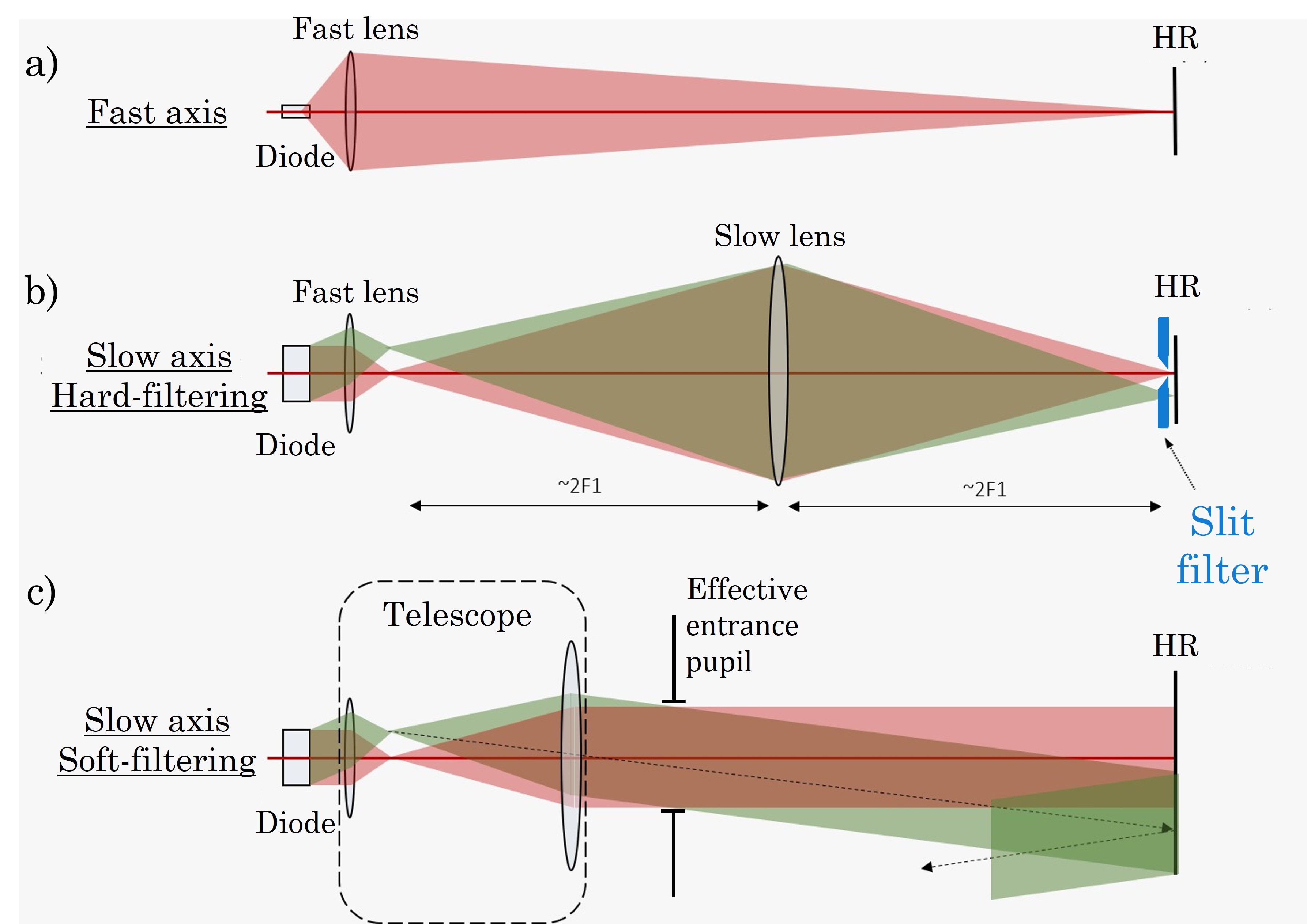
To implement a hard slit filter, the fast lens generates a Fourier-transform of the diode aperture at its back focal plane. This Fourier plane is then imaged by the slow lens to the end mirror, where a slit is positioned to filter a single spatial frequency (corresponding to a single plane wave at the diode) to provide feedback to the cavity. The multi-mode operation can be described as an incoherent sum of plane waves that propagate at different directions out of the diode, and are focused onto different points on the end mirror. The slit then selects a range of plane waves at the end mirror, where the width of the slit selects the number of allowed modes. This enforces a wide single-mode at the diode facet that covers most of the diode’s aperture. The magnification ratio of the two images on the end mirror (fast and slow) allows to compensate for the spatial astigmatism of the beam. As mentioned, the main problem with slit-filtering is the mismatch between the mode determined by the slit, and the mode determined by the diode, as will be demonstrated in the results section.
In contrast, the soft filtering approach moves the slow lens away from the imaging condition, towards the fast lens, which gradually reduces the accepted beam divergence at the diode plane, until finally only the fundamental mode with the lowest divergence can survive (a single plane-wave). This condition is reached when the slow-lens and the fast-lens form a telescope on the slow-axis, where the image of the diode acts as an effective entrance pupil for the beam in the return path (see figure 1c), which indicates that only a beam with sufficiently low divergence can safely pass the aperture in the backwards direction. When the separation of those two "aperture locations" approaches, or exceeds the Rayleigh range of a single-mode beam with a waist that matches the aperture width, only this lowest spatial mode can survive. Our filtering mechanism operates therefore between two spatial stability limits - the hard slit-filtering in figure 1b is equivalent to a concentric cavity and the soft filtering configuration of figure 1c is equivalent to a planar cavity.
III Results
To demonstrate the advantage of soft-filtering over hard filtering we used the experimental cavity configuration of figure 2, which is comprised of two arms around the diode - the right arm, which implements the spatial filtering (on both approaches) and a left arm, which supports all modes, and includes a variable output coupler, implemented by a polarizing beam-splitter and a rotating wave-plate that optimizes the output power (see caption of figure 2 for details). The left side is operated in the concentric configuration where the diode plane (near field) is Fourier-transformed onto the end mirror (far field). We therefore expect that at the transition from multi-mode to single-mode the beam profile at the left end mirror will converge into a narrow profile of minimum width accompanied by a maximal brightness, as illustrated in Fig. 3(a).
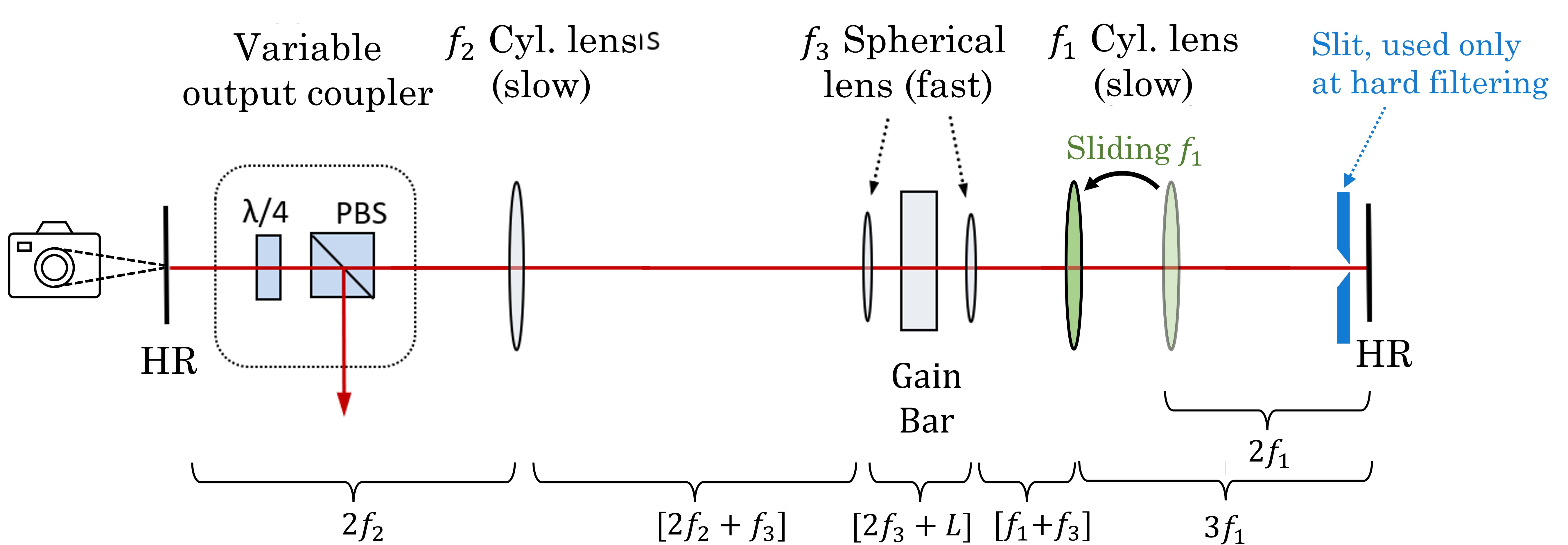
We employed in our experiments two broad-area diodes, to study low-power and high-power regimes: One diode of width and length, of relatively low power (up to multi-mode). Both diodes were AR coated to suppress self-lasing. The low power cavity was comprised of slow lenses with focal length: (right arm, filtering) and (left arm, output coupling) and the fast lenses focal length was . The high-power configuration (up to 2.6W multi-mode) used a larger diode with dimensions . In addition to the AR-coating, the diode was also placed at a small angle to the optical axis to suppress even further self-lasing from reflections of the end-facets. The focal lengths of the lenses in the high-power cavity were , , and .
III.1 Hard (slit) filtering
To explore the performance of hard-slit filtering in detail we first employed the lower power, diode in the configuration of figure 2 and measured the output power and the beam properties for varying slit widths, aiming to quantify the beam purity and the filtering power-efficiency. The diode was operated at a working current of , which is sufficiently above lasing threshold of the external cavity (A) to generate a highly multi-mode beam, but safely below the threshold for self-lasing of the gain chip alone () due to residual reflections from the diode facets.
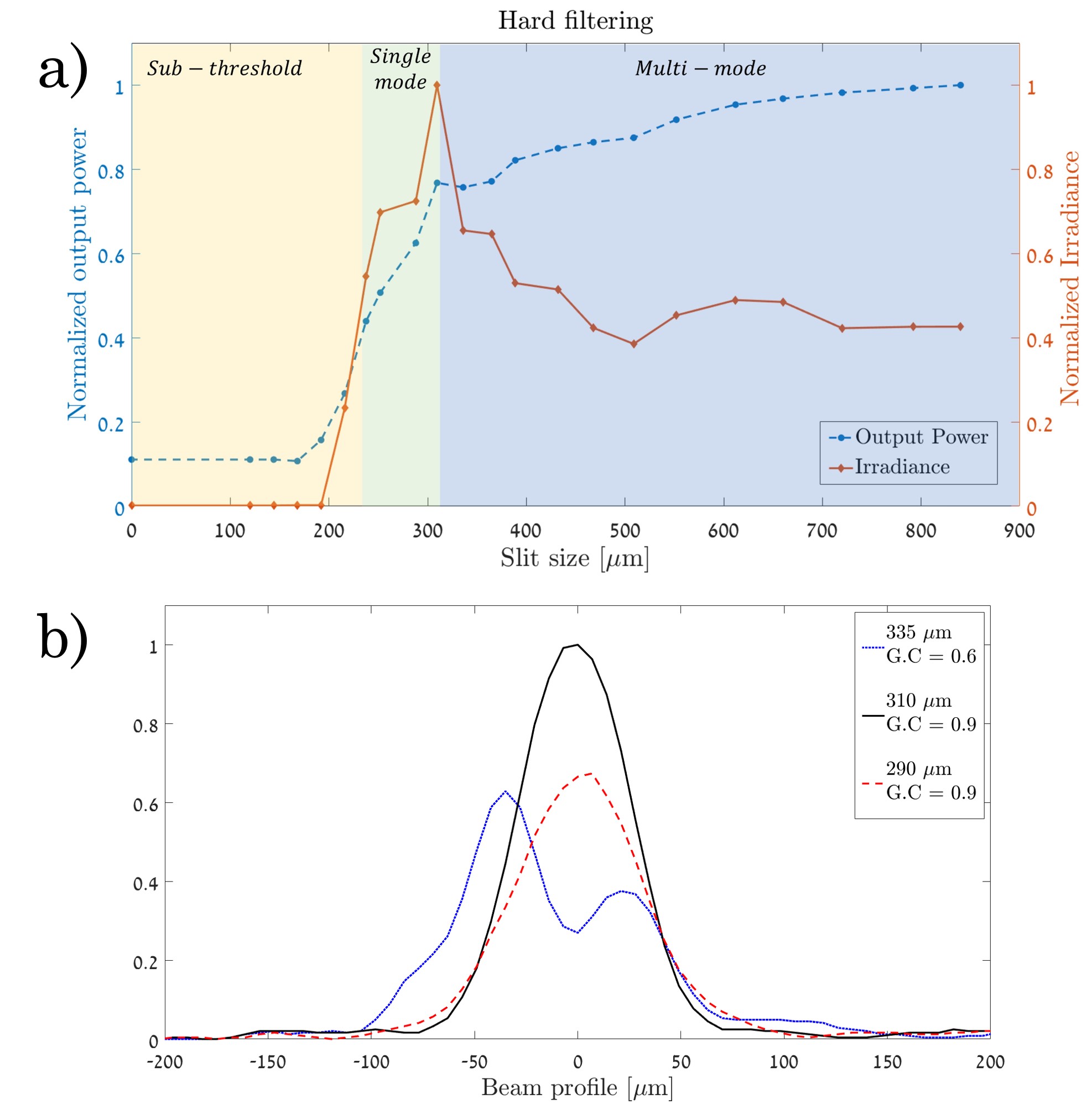
In the experiment we measured the output-power and the beam profile at the left end-mirror (using a CCD camera) for a varying slit width, as shown in figure 3. For each slit width we optimized the output coupler, to assure the maximal achievable power-efficiency. Single mode and multi-mode can be distinguished by examining the dependence of the beam irradiance (peak intensity) and the total power on the slit width. The goal of the method is to reduce the number of lasing modes. In spite of the slight reduction of the output power as the slit is closed, the irradiance rises considerably towards the single-mode condition, since the power is spread over less modes, as shown in Fig. 3(a).
Looking more closely at the beam properties, we measured the beam profile along the slow axis near the single-mode transition, as shown in figure 3(b). We observe the crossover point where the slit was sufficient to enforce single mode at (solid black). This is the optimal point, where the slit eliminates the additional modes (Gaussian content Ruschin et al. (2011)), while maintaining reasonable mode matching with the diode, such that the output power at single-mode is mW, which is of the multi-mode power at 2.2A. Closing the slit further (dashed red) remains single mode (Gaussian content ), but reduces the power due to increased losses from the slit also for the single-mode. With a wider slit, an additional mode arises, forming a dual-peaked beam profile (solid blue), reducing the Gaussian content to .
III.2 Soft-filtering
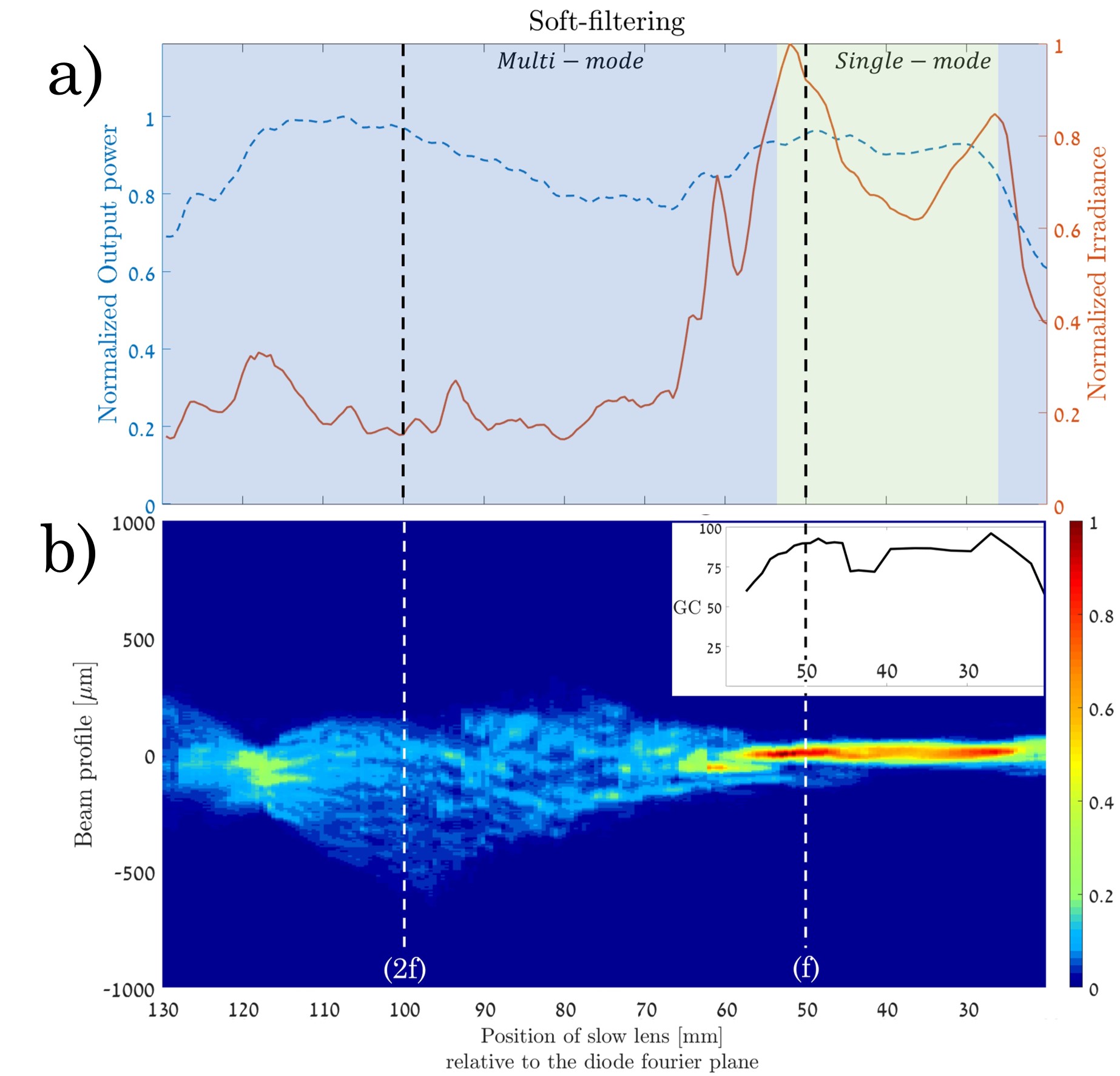
To demonstrate the soft-filtering method we shift the position of the slow (cylindrical) lens away from the imaging condition. Figure 4a shows the output power and output irradiance and figure 4b shows a line scan of the beam profile along the slow axis. both as a function of the position of the slow lens (relative to the back focal plane of the fast lens). The vertical dashed black lines mark the imaging location, where the beam is highly multi-mode and the telescope location , where the beam forms a nice single-mode with high Gaussian content (), with power that is nearly the same as the maximum multi-mode power (). This is a clear advantage over the hard filtering that showed only power efficiency at maximum.
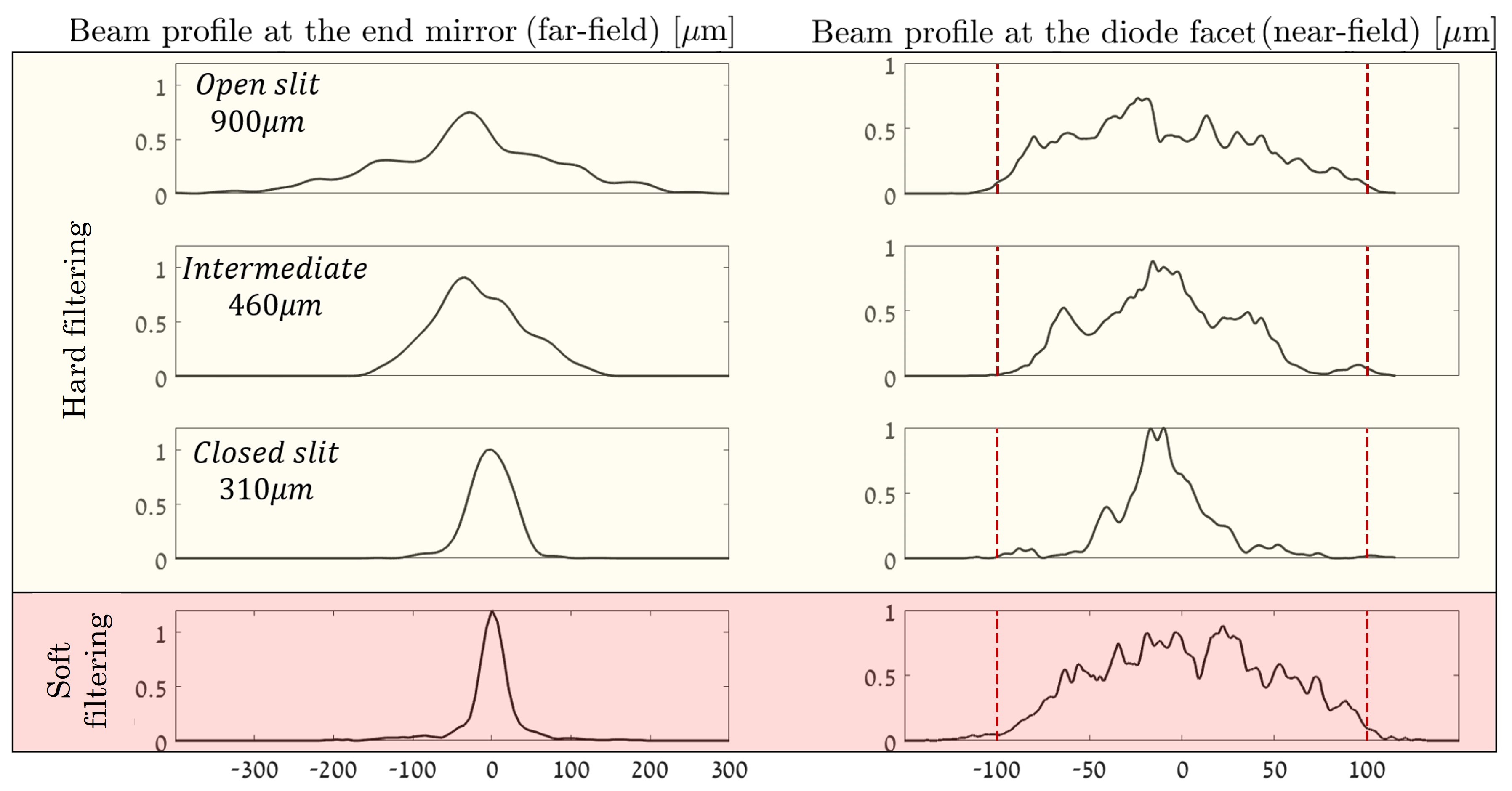
The superiority of the soft-filtering is also reflected when examining the beam fill-factor inside the diode, as shown in Fig. 5 that presents the beam profile on the diode facet (near field) and at the Fourier plane (far field) on the left end-mirror for both hard filtering (top three lines for different slit widths) and soft filtering (bottom fourth line). The physical borders of the diode wave-guide are marked on the near-field profiles by vertical red lines. The best possible fill-factor is represented by the top row, which shows multi-mode operation with no filtering restrictions on the laser operation. Ideally, the single-mode operation should reach a similar fill-factor. Clearly, the hard-filtering is not optimal in this regard, with a fill factor of roughly , whereas for the soft-filtering, the fill factor is nearly ideal. This difference is also reflected in the far field beam, where the soft-filtering profile is narrower than that of the hard-filtering, which highlights the fact that the slit mode for hard filtering does not perfectly match the fundamental mode of the diode wave-guide.
III.3 High-power results
All the results presented thus far were obtained with the narrower diode of dimensions, which could be driven only up to before self-lasing occurred, generating of output power at . To explore spatial filtering at higher power levels we introduced a wider and longer diode ( at ) into the experimental configuration. This wide diode can be driven by much higher currents (), however, to operate at such high currents, annihilation of self-lasing is absolutely necessary, and only the AR coating is not sufficient for this. To further suppress self-lasing, the wide diode was placed at an angle to the optical axis, which directs the residual reflection out of the diode’s wave-guide and prevents it from amplifying. We then applied both the hard and soft-filtering approaches to the high-power wide diodes and examined their performance and limitations.
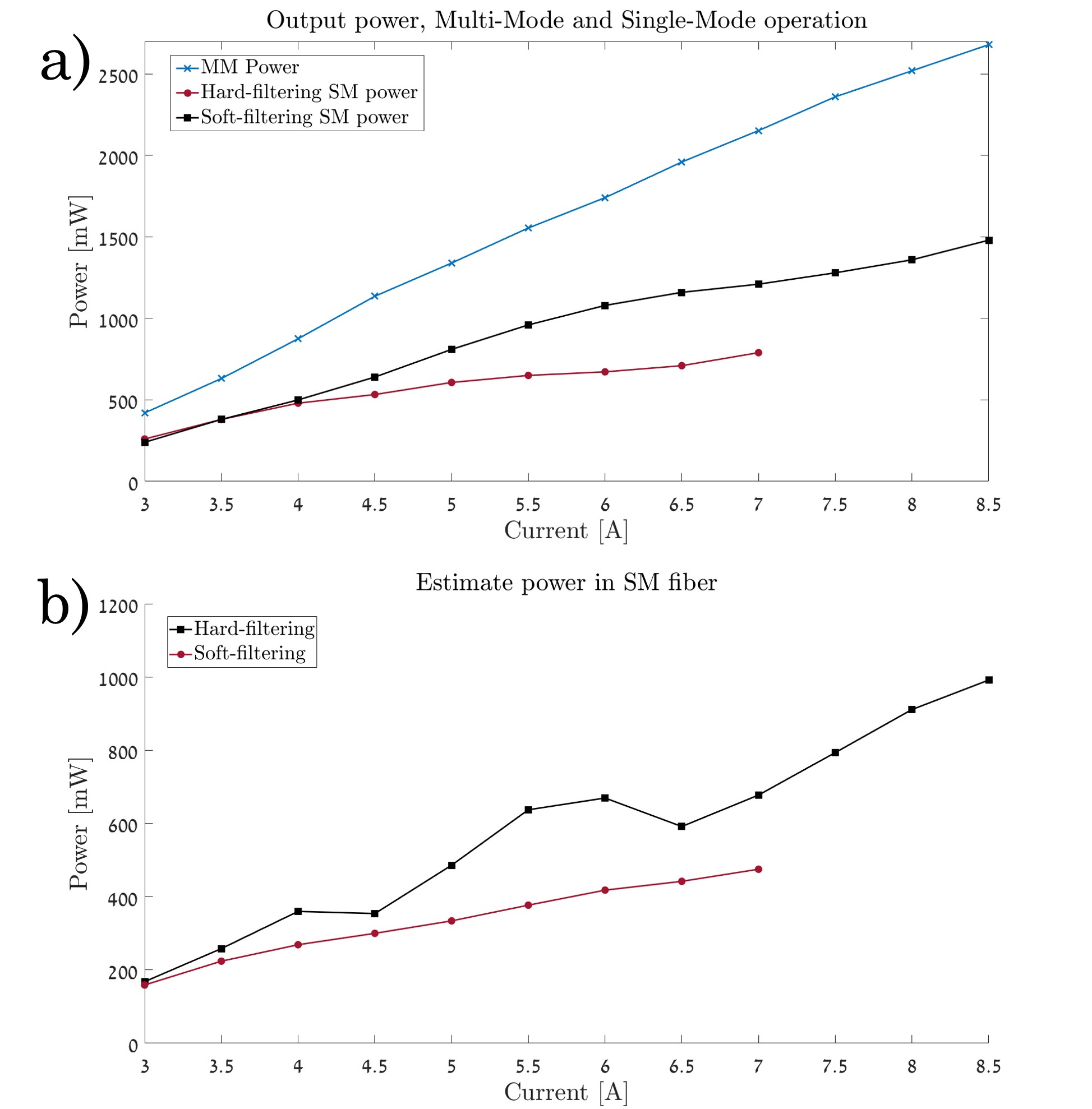
Figure 6a shows power-current (PI) curves of the wide diode in multi-mode (blue), as well as the optimal single mode configurations for both hard (black) and soft (red) filtering. Figure 6b presents the estimated power into a single-mode fiber based on the calculated Gaussian content of the output beam. Clearly, the soft filtering performed better than hard filtering in two aspects: First, the overall power efficiency was near for soft filtering, noticeably improved compared to hard-filtering. Second, with soft filtering the diode could be driven to higher currents, while maintaining single-mode operation. Specifically, the maximum current with soft filtering was , which generated of output power at single-mode, compared to at for hard filtering.
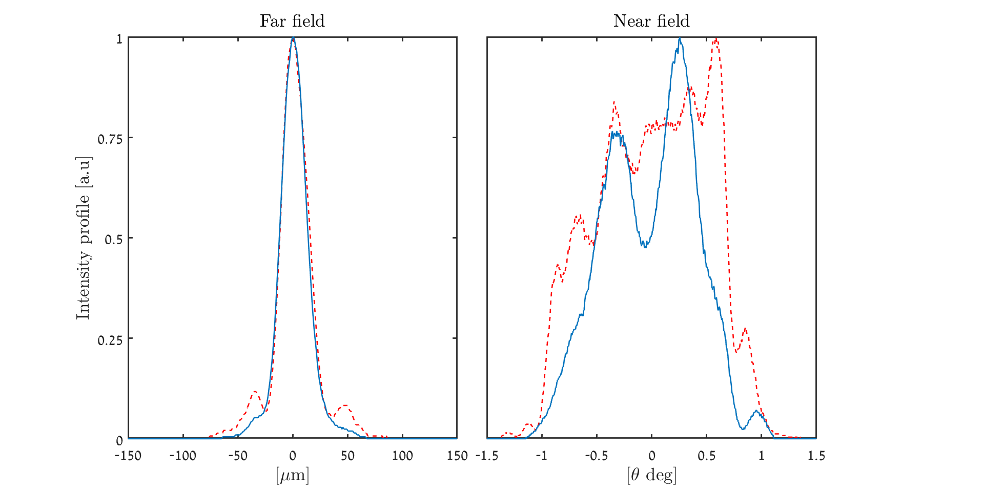
Finally we measured the beam quality of the single-mode beam for both soft and hard filtering using two parameters - and Gaussian content. The Gaussian content for all drive currents was between , and was obtained when low intensity side lobes and image noise (contain less than 10 percent of the total power) were omitted ( for the raw beam image) as demonstrated in figure 7 for .
IV Conclusions
We demonstrated soft spatial filtering in broad-area, high-power semiconductor lasers, where the diode aperture itself acts as the spatial filter in an external cavity configuration. We extracted up to of high-brightness power, with power that can be efficiently coupled to a single mode fiber. We demonstrate an improvement in the single mode power and irradiance compared to state-of-the-art methods of hard slit-filtering by roughly . Another advantage of our soft-filtering method is the ability to operate at higher working currents, without being negatively affected by self-lasing. Shaping the beam inside the cavity efficiently enforced single-mode operation in a very high-gain regime, which is highly desirable for many applications in the field of laser engineering.
References
- Price et al. (2010) K. Price, S. Karlsen, P. Leisher, and R. Martinsen, in High-Power Diode Laser Technology and Applications VIII, Vol. 7583, edited by M. S. Zediker, International Society for Optics and Photonics (SPIE, 2010) p. 758308.
- Bao et al. (2015) L. Bao, M. Kanskar, M. DeVito, M. Hemenway, W. Urbanek, M. Grimshaw, Z. Chen, W. Dong, X. Guan, S. Zhang, D. Dawson, and R. Martinsen, in High-Power Diode Laser Technology and Applications XIII, Vol. 9348, edited by M. S. Zediker, International Society for Optics and Photonics (SPIE, 2015) p. 93480C.
- Boller et al. (2000) K.-J. Boller, B. Beier, and R. Wallenstein, “Properties and frequency conversion of high-brightness diode-laser systems,” in High-Power Diode Lasers: Fundamentals, Technology, Applications: With Contributions by Numerous Experts, edited by R. Diehl (Springer Berlin Heidelberg, Berlin, Heidelberg, 2000) pp. 225–263.
- Klein et al. (1998) M. Klein, D.-H. Lee, J.-P. Meyn, B. Beier, K.-J. Boller, and R. Wallenstein, Optics letters 23, 831 (1998).
- Fritsche et al. (2015) H. Fritsche, F. Ferrario, R. Koch, B. Kruschke, U. Pahl, S. Pflueger, A. Grohe, W. Gries, F. Eibl, S. Kohl, and M. Dobler, in High-Power Laser Materials Processing: Lasers, Beam Delivery, Diagnostics, and Applications IV, Vol. 9356, edited by F. Dorsch, International Society for Optics and Photonics (SPIE, 2015) p. 93560I.
- Faircloth (2003) B. O. Faircloth, in High-Power Diode Laser Technology and Applications, Vol. 4973, edited by M. S. Zediker, International Society for Optics and Photonics (SPIE, 2003) pp. 34 – 41.
- Michalik et al. (2021) M. Michalik, J. Szymańczyk, M. Stajnke, T. Ochrymiuk, and A. Cenian, Micromachines 12 (2021), 10.3390/mi12060710.
- Fallahi and Bedford (2013) M. Fallahi and R. Bedford, in Semiconductor Lasers, Woodhead Publishing Series in Electronic and Optical Materials, edited by A. Baranov and E. Tournié (Woodhead Publishing, 2013) pp. 81–120.
- (9) M. Chi and P. M. Petersen, “15.1 edge emitters with external cavities: Datasheet from landolt-börnstein - group viii advanced materials and technologies · volume 1b3: “laser systems” in springermaterials (https://doi.org/10.1007/978-3-642-14177-5_15),” Copyright 2011 Springer-Verlag Berlin Heidelberg.
- Raab and Menzel (2002) V. Raab and R. Menzel, Opt. Lett. 27, 167 (2002).
- Mroziewicz (2008) B. Mroziewicz, Opto-Electronics Review 16, 347 (2008).
- Wolff et al. (2003) S. Wolff, A. Rodionov, V. Sherstobitov, and H. Fouckhardt, IEEE Journal of Quantum Electronics 39, 448 (2003).
- Chi et al. (2004) M. Chi, N.-S. Bøgh, B. Thestrup, and P. M. Petersen, Applied Physics Letters 85, 1107 (2004), https://doi.org/10.1063/1.1783017 .
- Mailhot et al. (2000) S. Mailhot, Y. Champagne, and N. McCarthy, Appl. Opt. 39, 6806 (2000).
- Ruschin et al. (2011) S. Ruschin, E. Yaakobi, and E. Shekel, Applied optics 50, 4376 (2011).