Update of beam coupling impedance evaluation by the stretched-wire method
Abstract
In many cases beam coupling impedances or wake fields are calculated with computer simulator such as CST Studio Suite, GdfidL Electromagnetic Field Simulator and so on. But evaluation with the stretched-wire method is still very useful by its flexibility to the change of the device-under-test configuration, speed to get results and, more than anything, its accessibility on the real devices. One of the drawbacks in the practical procedure, difficulty of Thru-Reflect-Line calibration, is overcome using the calibration method recently introduced in high frequency vector network analyzers, "2-X THRU de-embedding". Here the procedure is explained in detail. The method has been successfully applied to RF cavity and FX kicker measurement in the J-PARC MR.
1 INTRODUCTION
In recent operations of the J-PARC MR[1], longitudinal microstructure in the debunching bunches causes a problem including beam instabilities at the flattop energy in the slow extraction (SX) mode. In the fast extraction (FX) mode a similar problem is foreseen, because longitudinal phase space manipulation will be required for peak beam current reduction and debunching is included in this process. As a first step for understanding this longitudinal microwave instability and taking a countermeasure, we are evaluating the longitudinal coupling impedances of major devices of a large coupling impedance such as kickers, septa, RF cavities.
The stretched wire method is a widely used coupling impedance measurement method of the actual devices. The procedure was rather complicated for a rigorous measurement method which needs Thru-Reflect-Line (TRL) calibration [2]. A simplified method by measuring only a device under test (DUT), omitting other measurements and using numerical correction of phase shift cannot cancel the mismatch effect at the transition parts between 50 coaxial cables. This drawback is overcome using the calibration method recently introduced in high frequency vector network analyzers, "2-X THRU de-embedding". The procedure of this method is described and the present status of the mapping from to using conventional methods is reported.
2 PROCEDURE OF "2X-THRU de-embedding"
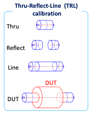
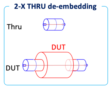
Setups for TRL and 2-X THRU de-embedding methods are summarized in Fig.1. The left figure shows the setup variation for the TRL method. "Thru", "Reflect", "Line" and "DUT" fixtures and measurements are necessary. The right figure shows the setup variation for the 2X-THRU de-embedding method [3]. The setup is much simplified. The time and effort of measurement is also simplified.
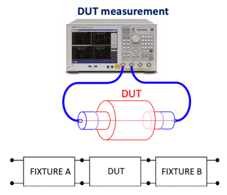

We can extract the DUT S-parameter by removing the effects of the FIXTURE A and B from the whole S-parameter in Fig. 2, by characterizing the S parameters of FIXTURE A and B, separately [3].
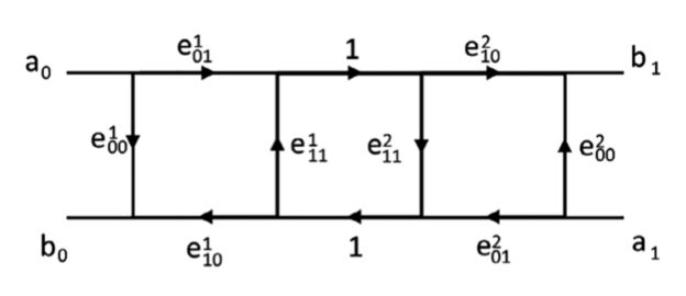
Originally, there are four equations of S-parameters for eight unknowns . Assuming that , , number of unknowns reduces to six. Variables and are obtained by the procedure intuitively summarized in Fig.3.
We can obtain by solving the equations
| (1) |
| (2) |
| (3) |
| (4) |
Then we extract the DUT S-parameter by removing the effects of the FIXTURE A and B. At the beginning of this procedure, a scattering matrix should be renormalized from the characteristic impedance of the network analyzer of 50 to that of the coaxial transmission line consisting of a wire and a circular pipe, , typically for a RF system and for a kicker system. Finally using and appropriate formula, obtain the longitudinal coupling impedance, . We tried three formulas, "standard log formula", "improved log formula" and "lumped element formula" [4]
| (5) |
| (6) |
| (7) |
where , is the angular frequency, the light velocity and is the length of the DUT.
3 of the Accelerating RF system
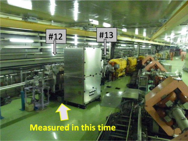
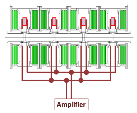
Our RF system in the MR has been upgraded according to the plan tabulated in Table 1 [1]. We measured newly installed RF system (cavity and final amplifier) at upstream of INS-A in the shutdown period in Sep. and Oct. 2021 (Fig.4). The setup can be changed between fundamental and 2nd harmonic resonance configuration by additional capacitors at the acceleration gaps (Fig.5). We measured several setups including a fundamental, 2nd harmonic, gaps shorted by bus bars and only gaps.
| Present | 2022 | 2026 | |
| MR Cycle | 2.48 s | 1.32 s | 1.16 s |
| Fundamental Cavities | 7 | 9 | 11 |
| 2nd Harmonic Cavities | 2 | 2 | 2 |
| Accelerating Voltage | 300 kV | 510 kV | 600 kV |
| 2nd Harmonic Voltage | 110 kV | 110 kV | 110 kV |
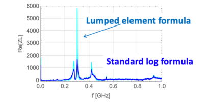
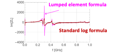
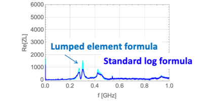
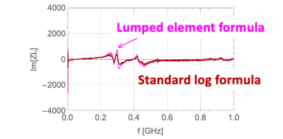
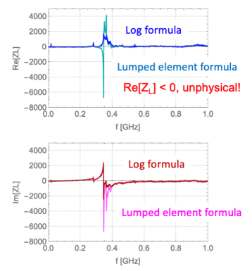
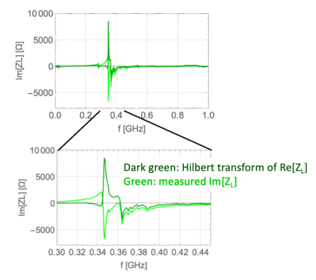
Results calculated by the lumped element formula and the standard log formula are shown in Figs.6 and 7. The lumped element formula may fit the short acceleration gap size of 30 mm rather than two log formulas which fit longer DUT. But the system here consists of four gaps distributed in two meters. In the case of shorted gaps at an upper part, by the lumped element formula goes negative in some frequencies, which is unphysical (Fig.8). Moreover Hilbert transform of and the measured are very far apart. This difficulty may come from inappropriate use of the formulas, Eqs. 5 to 7.
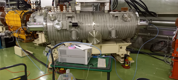
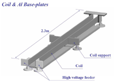
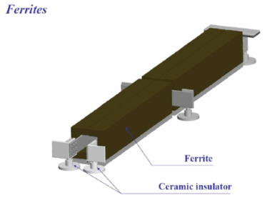
4 of the FX Kicker System
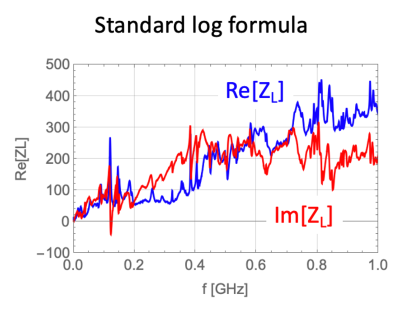
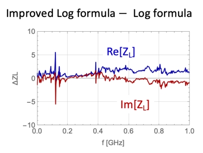
There are five tanks for FX kickers at INS-C in the MR [5]. We measured the fifth tank as shown in Fig. 9 in Jan. and Feb. 2022. The kicker structure is shown in Fig. 10. A matching circuit is attached on top of the tank. The power supply at the power supply building on the ground is connected with a feeder cables. The circuit is almost decoupled by a satuarable inductor. The left of Fig. 11 shows the calculated with the standard log formula. The difference between the impedance calculated by the standard log formula and one by the improved log formula is a few % of the as shown in the right.
5 SUMMARY AND PROSPECT
DUT S-parameters were successfully measured with "2X-THRU de-embedding". Then longitudinal impedances, , are calculated with conventional formulas. Validity of the process of mapping from to has been investigated. Hilbert transform of has been tested and one pair of data shows large discrepancy. Inappropriate use may be a reason. Careful comparison with the CST simulation is also under way. Besides above reported, transverse impedance measurements with two wires are also performed. Additional measurements with reference pipes are planned. With the impedances above measured, previously measured and calculated with CST studio, beam stability is being investigated with computer programs.
References
- [1] S. Igarashi et al., "Accelerator design for 1.3-MW beam power operation of the J-PARC Main Ring", Progress of Theoretical and Experimental Physics, Volume 2021, Issue 3, March 2021, 033G01, DOI: 10.1093/ptep/ptab011
- [2] L. Walling et al., "Transmission-line impedance measurements for an advanced hadron facility", Nuclear Instruments and Methods in Physics Research A281 (1989) 433- 447. DOI: 10.1016/0168-9002(89)91474-5
- [3] Ellison J, Smith SB, Agili S. "Using a 2x-thru standard to achieve accurate de-embedding of measurements.", Microw Opt Technol Lett. 2020;62:675–682. DOI: 10.1002/mop.32098
- [4] E. Jensen, "An improved log-formula for homogeneously distributed impedance", CERN-PS-RF-NOTE-2000-001.
- [5] K. Koseki and H. Matsumoto, "The fast extraction kicker for J-PARC with a novel pulse compression system", Nuclear Instruments & Methods in Physics Research Section A739 (2014) pp.63–67. DOI: 10.1016/j.nima.2013.12.040