A Domain-Specific Language for Simulation-Based Testing of
IoT Edge-to-Cloud Solutions
Abstract.
The Internet of things (IoT) is increasingly prevalent in domains such as emergency response, smart cities and autonomous vehicles. Simulation plays a key role in the testing of IoT systems, noting that field testing of a complete IoT product may be infeasible or prohibitively expensive. In this paper, we propose a domain-specific language (DSL) for generating edge-to-cloud simulators. An edge-to-cloud simulator executes the functionality of a large array of edge devices that communicate with cloud applications. Our DSL, named IoTECS, is the result of a collaborative project with an IoT analytics company, Cheetah Networks. The industrial use case that motivates IoTECS is ensuring the scalability of cloud applications by putting them under extreme loads from IoT devices connected to the edge. We implement IoTECS using Xtext and empirically evaluate its usefulness. We further reflect on the lessons learned.
1. Introduction
Simulation is an important validation and verification activity during the requirements and design stages, and before a proposed system has been built. For certain types of systems, simulation also plays a key role in later stages of development, e.g., when one needs to exercise scenarios that are too risky or too expensive to run in real-world deployments. Notably, simulation is the technique of choice for the validation and verification of systems that have high levels of autonomy, e.g., autonomous vehicles (Al-Sultan et al., 2014; Borg et al., 2021; Ahlgren et al., 2021), or massive connectivity, e.g., the Internet of things (IoT) (Shin et al., 2020; Li et al., 2022).
This paper is concerned with simulation in the context of IoT. IoT envisions complex systems that interconnect large numbers of smart devices, embedded with sensors and actuators, through the Internet or other network technology (Hung, 2017). IoT is already pervasive in several application domains, e.g., emergency response, smart cities, smart agriculture and autonomous vehicles, to name a few. IoT simulation has numerous facets, including simulation of IoT sensors and actuators (Kertész et al., 2019; Ama, 2021; Zeng et al., 2017), simulation of IoT edge devices (Jha et al., 2020; Sonmez et al., 2017) and simulation of IoT networks (Kliazovich et al., 2012; Österlind et al., 2006; Boulis, 2011; Min, 2021). Our work in this paper focuses on simulating edge devices and their interactions with cloud applications. An edge device is a generic term referring to any device that serves as an entry point to a network. In IoT, edge devices typically run applications and protocols for managing groups of sensors and actuators, performing edge computing (Elazhary, 2019), and sending and receiving data to and from cloud applications.
Specifically, we propose in this paper a model-based approach for creating edge-to-cloud simulators. An edge-to-cloud simulator executes the functionality of a large number of edge devices that run in parallel and communicate with cloud applications either synchronously or asynchronously (Elazhary, 2019). Edge-to-cloud simulators may be employed for purposes such as testing and decision making, e.g., about how frequently edge devices should communicate with the cloud, and how to schedule the data flow from IoT devices so that the overall network traffic remains stable and burst-free (Wang et al., 2021).
Our work in this paper addresses a specific yet important need in IoT: Scale testing of cloud applications. Scale testing is concerned with understanding how a system behaves under an extreme workload and at the upper limits of its capacity (Chan, 2004). In our context, the workload originates from the edge devices and is destined for processing and storage by the cloud. Existing feature-rich IoT simulators, e.g. (Jha et al., 2020; Sonmez et al., 2017), are not good fits for cloud scale testing, noting that a feature-rich simulator may require substantial computational resources (CPU, memory and storage) to simulate thousands of devices. Many IoT providers use hosted services for simulation. The more resource-intensive the simulator, the more difficult it is to set up and the higher is the cost of running it for scale testing.
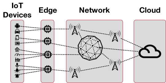
Figure 1 shows a schematic view of a typical IoT system. In a real IoT system, a network sits in between the edge and cloud layers. In our work, we need to ensure that the network does not act as a limiter for how far simulated edge devices can stress the cloud. We therefore connect the simulated edge layer to the cloud via an ideal network with no loss and minimally low transmission time. For experimentation purposes, we create this ideal network using a single network switch, discussed in Section 4.2.
Contribution. Building a well-functioning edge-to-cloud simulator involves various technical considerations, including proper use of communication protocols, managing the massive concurrency of simulated edge devices, and efficient use of computing resources. Due to these considerations, building an edge-to-cloud simulator from scratch can be a daunting task. To facilitate the construction of edge-to-cloud simulators, we propose a domain-specific language (DSL), named IoTECS (the IoT Edge-to-Cloud Simulation language). IoTECS provides abstractions that shield software engineers from several complexities of edge-to-cloud simulation, while still affording good customizability for different systems and different resource constraints. Specifications (models) written in IoTECS are automatically translatable into operational Java-based simulators. IoTECS has been developed in response to industrial needs and is the outcome of a collaborative research activity with Cheetah Networks – a leading provider of IoT analytics solutions. IoTECS has been already adopted by Cheetah Networks for stress testing some of their cloud applications.
Following ideas and guidelines from the literature on multi-agent simulation (Scheffer et al., 1995), IoTECS employs a hierarchical architecture for grouping large arrays of simulated edge devices. The resulting groups can subsequently be emulated through containerization, virtualization, or a combination thereof. IoTECS further supports configurable time gaps for orchestrating the execution of parallel edge devices; this is to ensure that messages between the edge devices and the cloud applications are communicated at a rate that is in line with real-world expectations in a specific IoT system.
Evaluation. We have applied IoTECS for stress testing a benchmark cloud as well as industrial cloud applications at our partner, Cheetah Networks. To evaluate IoTECS, we first ensure that it can reliably simulate a large number of parallel edge devices without incurring data loss. We scale simulation to generate 24000 packets per second using a single conventional laptop computer. These packets represent the data generated by 12000 (simulated) IoT sensors and actuators that communicate with the cloud every 500 milliseconds. We show how IoTECS can help engineers determine in a systematic way the number of IoT and edge devices that the cloud applications under test can handle. We further reflect on our experience and lessons learned using IoTECS in an industrial setting.
Structure. Section 2 motivates our use case for IoT edge-to-cloud simulators. Section 3 presents our DSL. Section 4 describes our evaluation of the configurability and usefulness of the DSL. Section 5 highlights industrial adoption and lessons learned. Section 6 compares with related work. Section 7 concludes the paper.
2. Motivating Use Case
This research resulted from a collaboration with Cheetah Networks (http://cheetahnetworks.com). Cheetah Networks develops AI-based solutions for real-time monitoring of quality of experience (QoE) in IoT networks. Below, we present the use case that motivated our research. For confidentiality reasons, we do not discuss the use case over our industry partner’s products, noting that some of these products are yet to be announced and released. Instead, we use a generic example from the domain of smart cities (Halegoua, 2020); this example has the representative characteristics of IoT edge-to-cloud solutions, which is what our work focuses on.
In a smart city, sensors monitor a wide range of parameters including, among others, weather, lighting, motion, traffic conditions, utility consumption, water chemistry, and air pollution. The information that these sensors collect is used for decision making and giving commands to actuators that control, for example, traffic and street lights, alarms, barrier gates, pumps, and heating and cooling systems. The sensors and actuators that are in close proximity are grouped together and connected in a wired or wireless manner to an edge device, also known as a gateway. Gateways typically have limited computational power, performing only basic data analysis. A gateway sends sensor data – potentially after some processing – to cloud services. The communication between a gateway and the cloud is routed through a core network. Upon receiving unprocessed or semi-processed sensor data, the cloud services perform a more comprehensive processing of the data, generate analytics, determine any necessary course of intervention, and send instructions back to the gateway, which will in turn communicate the instructions to actuators.
Our smart-city example is an instantiation of the IoT architecture in Figure 1. Within this example, consider the various data storage, data analysis, and decision-making services deployed in the cloud. An important question that the providers of these services need to answer is how far their services will scale in the face of extreme loads from a large number of IoT sensors, actuators, and gateways. Simulation is the most practical strategy for answering this question, noting that a physical IoT testbed for stressing cloud applications is often prohibitively expensive to build.
Creating a reliable simulator nonetheless presents its own challenges. In particular, implementing, within a practical budget, the concurrency and network-based communication required for mimicking a large number of IoT gateways connected to an even larger number of sensors and actuators is a complex technical endeavour. In this paper, we set out to develop an edge-to-cloud simulation DSL that abstracts away from much of the complexity of the underlying concurrency and networking technologies. Through this DSL, we aim to enable software engineers to build reliable edge-to-cloud simulators without requiring extensive knowledge of containerization, virtualization and network protocols.
3. Edge to Cloud Simulator
IoTECS is a domain-specific language (DSL) built on top of the conceptual model shown in Figure 2. This conceptual model aims to support a scalable and parameterizable architecture for capturing the communication between edge devices and cloud applications, and to enable simulation-based stress testing of edge-to-cloud solutions. We explain our conceptual model in Section 3.1. This is followed by a discussion of IoTECS syntax and usage in Section 3.2.
3.1. The IoTECS Conceptual Model
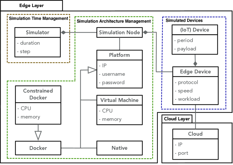
The concepts in the conceptual model of Figure 2 are arranged under two packages: Edge Layer and Cloud Layer. As described in Section 1, these two layers communicate through a network. The topology of this network is abstracted away in our model since, as argued in Section 1, for stress testing of cloud applications, an ideal network is placed between the edge and cloud layers. In our model, network-related information is limited to node IPs, port numbers and communication protocols. This information is captured as necessary within the edge and cloud concepts.
Cloud Layer. The Cloud concept shown in Figure 2 represents a cloud application under stress testing. For an edge-to-cloud simulator to be able to connect to the cloud under test, we need the IP address of the cloud’s host and the port at which the cloud receives incoming data. In IoTECS, we can test several cloud applications by instantiating Cloud multiple times.
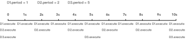
Simulation Time Management. The top-level Simulator concept in Figure 2 captures the attributes required for managing time. We execute each simulation for a given duration and divide this duration into equal time steps. We use the duration and step attributes to refer to the total simulation duration and to the duration of individual time steps, respectively. For example, Figure 3 depicts a simulation run where the duration is s and each step takes s.
Simulated Devices. The concepts here are IoT Device and Edge Device. IoT devices encompass sensors (e.g., temperature sensors) and actuators (e.g., traffic lights). IoT devices connect to and communicate periodically with edge devices by wired or wireless links. For example, a temperature sensor may communicate temperature readings to an edge device every s. Edge devices can assume a variety of roles, but their primary function is controlling the data flow at the boundary of a network. Edge devices may perform part of the required processing close to the source (IoT devices) instead of relying on the cloud to do all the processing, which is expensive and can further lead to latency. Edge devices nonetheless usually have limited processing and storage capabilities, and their view on data is limited as well. Edge devices are thus not a substitute for the processing and storage done by the cloud.
Ultimately, what we aim to achieve through IoTECS is high-fidelity simulation of edge devices. For this, we do not need to explicitly simulate IoT devices through individual processes or threads. Neither do we need to distinguish between IoT sensors and actuators, noting that both can have two-way communication with edge devices. Instead, as we elaborate below, we incorporate the relevant properties of IoT devices into the execution of (simulated) edge devices. For succinctness, where there is no ambiguity, we refer to a sensor or actuator simply as “device”. In contrast, when we mean an edge device, we use the term “edge device”.
Each instance of IoT Device has a period attribute, indicating the time interval (in terms of the number of simulation steps) between two successive executions of the IoT device. For example, an IoT device with period executes its function every step and the one with period executes every other step (e.g., see Figure 3). Given a set of devices, we choose the size of the step for our simulator as the greatest common divisor of the devices’ periods. For example, if we have two devices, one executing every s and the other every s, then the size of the step for our simulator is set to s. IoT devices, whenever they execute, generate a data packet whose size is specified by the payload attribute.
Each instance of Edge Device owns a group of IoT devices. At every time step, each edge device collects the data packets generated by its associated IoT devices. As mentioned earlier, in IoTECS, the IoT device concept does not induce executable entities. Instead, each instance of an edge device, which is an executable entity in IoTECS, is responsible for emulating the behaviour of the IoT devices associated with it. We provide a precise characterization of the behaviour of edge devices later, when we discuss Algorithm 1.
Edge devices send the collected packets to the cloud following the communication protocol indicated by the protocol attribute in Edge Device. For example, in Figure 3, suppose that one edge device is associated with IoT devices D1, D2, and D3. At time 0, the edge device sends the packets from all three to the cloud. At time 1s, it sends the D1’s packet, and at time 2s, it sends the packets from D1 and D2 to the cloud. In parallel with sending packets, the edge device performs two more operations: (a) receiving data from the cloud, and (b) performing compute-intensive operations (i.e., edge computing). Edge devices use a workload attribute to specify the time duration, measured in milliseconds or nanoseconds, spent on compute-intensive operations.
In addition to the protocol and workload attributes, Edge Device has a speed attribute that specifies how many packets an edge device sends to the cloud per simulation time step. To illustrate, let the simulation time step be s. If we set speed to , the edge device sends up to packets over s. That is, the edge device waits for ms after sending each packet to the cloud. In the above, we say “up to” because the edge device may send fewer packets if its associated IoT devices produce less packets than what the speed attribute allows to be transmitted. Similarly, if we set speed to , the edge device waits for ms after sending each packet. To indicate that an edge device can send packets at maximum speed over the time step duration (i.e., without any waiting after sending a packet), one can set speed to a designated value, MAX.
We use speed to control the time gap between the sending of the packets. If a large number of (simulated) edge devices attempt to send all their packets to the cloud without any time gap, the simulator may not be able to cope with all the send requests, or these requests may congest the network. In both situations, one may experience packet loss or latency at the (simulated) edge or within the network. In view of our goal, which is to stress test cloud applications, we need to make sure that we do not incur packet loss or latency at the edge or in the network. Using the speed attribute, we can pace the send requests in a way that would prevent the simulator and the network from being overwhelmed. This in turn allows us to rule out the simulator and the network as the root cause of packet loss and thus localize packet-loss occurrences to the cloud applications. In our empirical evaluation of Section 4, we demonstrate the impact of speed on our results.
Algorithm 1 formally specifies the behaviour of edge devices in IoTECS. An edge device performs three operations in parallel: sending packets, receiving packets and performing (edge) computing. At every time step between to where is the simulation duration and is the size of the step, the edge device checks each of its associated IoT devices (line 5). If the period of an IoT device indicates that it should be executed at step (line 6), then sends the associated payload to the cloud (line 7). After sending the data, may wait for some time gap whose size depends on the speed parameter of (lines 8-9). The loop for sending the IoT devices’ data to the cloud (lines 5-12) ends as soon as the time step has elapsed (line 11-12). As a result, if the time step is too short or too many IoT devices are associated to , some may fail to send their data packets to the cloud.
The receive method is used for receiving packets transmitted from the cloud to edge device (lines 13-14). To simulate edge computing in IoTECS, edge devices perform, for the duration specified by the workload attribute, some compute-intensive operation (lines 15-16). Note that to properly simulate edge computing, we need to explicitly perform operations that keep the edge CPU busy so that the CPU is not allocated to other parallel tasks. To this end, we perform a series of floating-point operations. Algorithm 1 stops when the simulation duration elapses.
Simulation Architecture Management. An important factor in edge-to-cloud simulation is the ability to simulate a large number of IoT and edge devices. As discussed above, each edge device manages the sending of the packets related to its IoT devices sequentially and within the simulation time step . This assumption matches practice, since in the real-world, edge devices directly handle their related IoT devices. The edge devices themselves, however, run in parallel and are independent from one another. The concepts under Simulation Architecture Management enable a more orderly handling of concurrency, in turn allowing us to optimize the number of edge devices that can run in parallel.
To maximize the capacity of our simulator in terms of the number of parallel edge devices, we introduce an additional tier into our simulator’s architecture to group the edge devices into clusters. This tier is represented by the Simulation Node concept in the model of Figure 2. Each simulation node is associated with a platform, represented by the Platform concept. Edge devices that belong to a given simulation node all execute in parallel and on the platform of the simulation node. The Platform concept has as attributes IP, username and password to enable access to the platform host machine. In IoTECS, Platform is specialized into Native (i.e., running on a native operating system), Virtual Machine and Docker. For a virtual machine (VM), we need to specify the CPU and memory attributes, respectively indicating the CPU and memory allocated to the VM. Docker containers can be unconstrained or constrained. For the latter (i.e., Constrained Docker), similar to a VM, we need to specify the CPU and memory attributes.
The idea of clustering edge devices into simulation nodes in order to scale simulators is inspired by the notion of “super indivduals” in massively multi-agent simulators (Scheffer et al., 1995). In our context, such clustering provides a mechanism to reduce contention over CPU, memory and ports. For example, instead of running 100 parallel edge devices on a single computer, we create ten dockers by dividing the single computer resources (CPU, memory and ports) between the dockers equally. We then use each docker to host ten (simulated) edge devices. As we will demonstrate in our evaluation of Section 4, the docker option considerably improves the scalability of our simulator, compared to the native option.
Another motivation for defining simulation nodes is to be able to restrict the amount of resources used for simulation, thus keeping the cost of simulation within reasonable limits when computation resources need to be purchased from third-parties. We will come back to this in our lessons learned (Section 5), when we discuss cost-awareness for simulation.
The behaviour of Simulation Node is specified in Algorithm 2. Each simulation node, upon creation, initializes each of its associated edge devices (lines 1-2). It then executes the edge devices in parallel (line 3). That is, Algorithm 1 is called for each edge device.
Algorithm 3 shows the overall behaviour of our simulator. The simulator starts by initializing the platforms of the simulation nodes (line 3). It then transfers the simulation code to the platforms (line 4). Next, the simulation nodes start to run in parallel on their respective platforms (line 5). The nodes run until the simulation duration elapses (line 6), at which point the nodes and their platforms are cleaned up (lines 7-9).
Our simulator can be configured to represent different numbers of IoT and edge devices. As these numbers increase, the application(s) in the cloud layer are put under more stress. In this way, our simulator makes it possible to determine how far the cloud application(s) under test can be stretched without degradation in their quality of service. Upon the termination of a simulation round, we collect certain metrics, defined in Section 4.3. These metrics help determine (1) whether, given the computational resources made available, the simulator can mimic the desired numbers of IoT and edge devices without getting overwhelmed, and (2) whether the cloud application(s) are able to process and respond in reasonable time to all the messages received from the simulator.
3.2. The IoTECS DSL
IoTECS aims to support practitioners in creating simulators that are instances of the conceptual model of Figure 2. We provide an implementation of IoTECS using Xtext (Eclipse Foundation, Inc., 2021b). Specifically, we use Xtext’s grammar language to define IoTECS’s grammar. To generate executable simulators from specifications written in IoTECS, we use Xtend (Eclipse Foundation, Inc., 2021a). More precisely, we use Xtend to retrieve all the objects defined in an IoTECS specification; these objects in turn drive the instantiation of a number of a-priori-defined Xtend templates. Our Xtend templates include: (1) Java-based implementations of the algorithms in Section 3.1, (2) scripts for setting up / starting virtual machines and containers, (3) scripts for uploading and running simulator code on remote platforms, (4) scripts for downloading simulation results from simulation nodes, and (5) scripts for analyzing and reporting simulation results.
We make IoTECS’s Xtext grammar and Xtend templates publicly available (IoT, 2022). In the rest of this section, and noting that the design of IoTECS follows well-established DSL engineering practices using Xtext, we adopt a practitioner-oriented perspective and emphasize examples of IoTECS usage; full details about the design of IoTECS can be found in our artifacts (IoT, 2022)
Cloud. Figure 4 shows a snippet of an IoTECS specification specifying two Cloud instances. For each instance, the IP and port attributes respectively specify the IP address of the cloud application’s host machine and the port at which incoming packets are received. We note that the code for instances of Cloud is not meant to be generated by IoTECS. Rather, each Cloud instance represents an existing cloud application that needs to be stress-tested.
Simulator. Each IoTECS specification has exactly one instance of the Simulator concept. To illustrate, consider the snippet in Figure 5. Here, the simulator has its duration set to 10s and its step to 1s; this results in dividing the simulation into 10 steps of equal length with each step running for 1s. The time unit for duration and step can be in milliseconds (ms), seconds (s), minutes (m) or hours (h). A simulator needs to declare its simulation nodes. This is done as illustrated on line 4 of Figure 5. On this line, we are stating that the simulator has six simulation nodes: five nodes of type SN1 and one node of type SN2. We next illustrate how to define the simulation node types (in this case SN1 and SN2) and their associated execution platforms.
Simulation nodes and platforms. As discussed in Section 3.1, IoTECS uses the notion of simulation node for grouping simulated edge devices and to further specify the platform on which a group of edge devices run. In the snippet of Figure 6, we define two simulation node types, SN1 and SN2, each having a set of edge devices and a platform. Similar to our convention for specifying the simulation nodes contained in a simulator (see Figure 5), we define the edge devices contained in a simulation node via an edge-device type and a number of instances. For example, in Figure 6, SN1 has ten edge devices: seven of type E1 and three of type E2 (we will momentarily illustrate the specification of edge-device types).
Each platform has a type that assumes one of the following values: Native, VM or Docker. To be able to run a simulation node when its platform is remote (i.e., not the local host), the simulation code and scripts need to be transferred to and set up on the platform first. For this purpose, we need to specify an IP and login credentials (username and password) in instances of the Platform concept. This is illustrated by platform P2 (of type Docker) as specified on lines 12-19 of Figure 6. When the platform is local, this information is not needed, as illustrated by platform P1 on lines 9-11 of the same figure. To be precise with respect to our conceptual model of Figure 2, for a local platform, the username and password can be viewed as being empty and the IP as 127.0.0.1. For a Docker platform that is constrained and for any VM platform, we specify the required attributes indicated in our conceptual model of Figure 2. For example, platform P2 is a constrained docker with 4 CPUs and 2G of memory.
Edge and IoT devices. Each edge device has a set of IoT devices associated to it. For example, in the snippet of Figure 7, edge-device type E2 is associated with 10 IoT devices of type D1 and 20 IoT devices of type D2 (we will shortly exemplify IoT-device types).
Each edge device communicates with one cloud application. For example, in Figure 7, E1 is specified as communicating with cloud application C1. The protocol used by an edge device for communication with the cloud is captured by the protocol attribute. Currently, IoTECS supports the UDP, TCP and MQTT protocols. The speed attribute describes the number of packets sent to the associated cloud application in one time step. For instance, in Figure 7, the speed is set to 100 for E1 and 1000 for E2. Since step has been set to 1s (see Figure 5), E1 waits 10ms between sending two consecutive packets; this wait time is 1ms for E2. The workload attribute indicates the amount of edge computing to be done by the edge device (lines 15-16 of Algorithm 1). The time unit for workload can be milliseconds (ms), seconds (s) or minutes (m). Note that, in parallel with sending packets and edge computing, an edge device also receives packets from the cloud (lines 13-14 of Algorithm 1). The protocol for receiving data from the cloud is the same as that used for sending data to the cloud (i.e., is as specified by the protocol attribute).
Each IoT device (type) has two attributes. The first one is period which determines the frequency of execution. For example, in the snippet shown in Figure 8, device D1 generates a packet every second, while device D2 generates a packet every two seconds. The second attribute is payload. This attribute can be used to specify the actual payload content, e.g., payload: "23C", or alternatively, the size of the packet that the device sends every time the device executes. In the latter case, the payload unit can be bytes (B), kilo bytes (kB) or mega bytes (MB). When a size unit is indicated for the payload, the content of the payload is generated randomly as per the requested size. This option, illustrated in Figure 8, is convenient when the actual payload is unimportant for simulation purposes (e.g., in a simple cloud storage application).
4. Evaluation
In this section, we evaluate the applicability and usefulness of simulators generated from IoTECS specifications for stress testing of cloud applications. We use the term simulator to refer to the executable code generated from instantiating the edge-layer concepts of the model of Figure 2; we use the term cloud to refer to instances of the cloud concept in this model. For our experiments, as we discuss in Section 4.1, we create our own baseline cloud applications. The research questions (RQs) that we investigate are as follows:
RQ1. (Configuring Simulators) Can we configure our simulator so that it can successfully simulate a large number of IoT and edge devices? With RQ1, we examine whether the simulator architecture envisaged by the conceptual model of Figure 2 allows one to instantiate a large number of IoT and edge devices as required by our motivating use case (Section 2). For practical reasons, we want the whole simulator to run successfully on a single computer with modest resources. In RQ1, we assess how grouping edge devices into simulation nodes and executing simulation nodes on alternative platforms (native, virtual machine and docker) impacts the ability of simulators to scale. The results of RQ1 lead to a configuration range for simulators in terms of the number of IoT devices, edge devices and simulation nodes as well as the platform types.
RQ2. (Cloud-Application Stress Testing) Can our simulator be used for stress testing cloud applications and determining the number of IoT and edge devices that a cloud application can handle? We perform simulations using the configurations identified in RQ1 to assess how well one can push a cloud application to its limits in terms of the number of IoT and edge devices being handled.
4.1. Baseline Cloud Applications
Due to confidentiality, for RQ1 and RQ2, we do not report quantitative results over our partner’s cloud applications. Instead, we build our own baseline cloud applications and apply to these baselines the same analysis as that performed on our partner’s applications. The results we report for RQ1 and RQ2 are over the baselines. Our baselines implement a simple loop where an instance of the cloud concept receives a packet from an edge device, performs compute-intensive operations for a configurable duration, cloudComputing, and sends the received packet back to the sender. The compute-intensive operations are meant at simulating cloud computing. We create three baselines, varying the cloudComputing parameter to , ms, and ms, respectively.
4.2. Experiment Design
To answer RQ1 and RQ2, we use two computers, one for running the simulator and one for running a baseline cloud application.
Consistent with our objective of abstracting away from the complexities of networks (discussed in Section 1), we connect the simulator to the cloud via a single switch as shown in Figure 9. This setup, while simple, provides a high-fidelity testbed for stress testing of cloud applications, as it routes all network traffic through the switch (ideal network) rather than a real-world network that may not be as reliable or predictable. Requiring the simulator to run on a single machine (laptop) was in line with the needs of our partner; they needed the simulator machine to be portable so that it could be brought to different sites and connected to different networks.
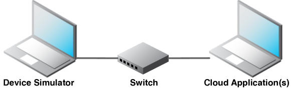
Table 1 shows the configuration parameters for our experiments. We select the duration of simulations to be s and the time step to be s (i.e., four steps in each simulation). For the device payload size, we follow the recommendation of our collaborating partner, and set it to . We set the period of each IoT device to 1 to maximize the number of messages sent in each time step. Based on the recommendation of domain experts, we configure virtual machines and constrained dockers with four CPU cores and G of memory. For edge devices, we eliminate edge-computing time by setting edge.workdload to zero, noting that our goal is maximizing communication with the cloud. For the number of IoT devices per edge device and the number of edge devices per simulation node, we followed the recommendation of our partner based on past examples of large-scale IoT rollouts.
| duration | 2s | cloud computing time | 0/1/5ms |
|---|---|---|---|
| time step | 0.5s | # of sim nodes | 8 to 12 |
| # of IoT devices per edge device | 100 | # of edge devices per sim node | 10 |
| (IoT) Device.period | 1 | (IoT) Device.payload | 8B |
| Edge Device.workload | 0 | Edge Device.speed | Max, 500, 250, 167, 125 |
| Virtual Machine.CPU | 4 | Constrained Docker.CPU | 4 |
| Virtual Machine.memory | 2G | Constrained Docker.memory | 2G |
To answer RQ1, we executed our simulator using the parameters of Table 1. Specifically, for the speed of edge devices, we insert a time gap of ms, , , and between the consecutive messages sent, resulting in the edge device speed to be set, respectively, to MAX, , , and . Note that further decreasing the speed (i.e., increasing the gap time) leads to inconsistency in our experimental setup since each edge device needs to be able to send 100 messages in a time step (i.e., one message per IoT device). For the number of simulation nodes, the partner was interested in having ten. Nonetheless, the partner was also interested in determining how far the simulation could be pushed on the laptop that we were using without the simulator showing anomalous behaviours. Based on this requirement, we experimented with 10 2 simulation nodes, thus the range of to nodes in Table 1. With these numbers of simulation nodes, we use our simulator to capture between to IoT devices where each is sending a message every half second to the cloud. We executed each configuration of our simulator for four platform options: Native, Virtual Machine (VM), Constrained Docker (CDC) and Unconstrained Docker (UDC). We assumed that the cloud is not doing any cloud computing (i.e., cloud computing = 0), since the purpose of RQ1 is configuring the simulator. This in turn requires operating under the assumption that the cloud responds as promptly as possible. In total, to answer RQ1, we performed 100 experiments (# of platforms = 4) (# of speeds = 5) (# of sim nodes = 5). We repeated each experiment 10 times to account for random variation.
To answer RQ2, we consider the simulation configurations that, based on the results of RQ1, can successfully execute on a single machine and send all messages to the cloud. We then rerun these configurations for two cloud instances where their computing time is set to ms and ms, respectively. That is, in contrast to the cloud instance used for RQ1, here, we consider cloud instances that have to preform some computing tasks after receiving messages and before responding. For RQ2, we perform 100 experiments (# of platforms = 2) (# of speeds = 5) (# of sim nodes = 5) (# of alternative cloud instances = 2) and repeat each experiment times to account for randomness. Note that, for RQ2, we consider the CDC and UDC platforms only. This is because the VM and Native platforms could not pass the sanity check in RQ1: in our experimental setup, these platforms could not successfully run the simulator without incurring packet loss. We executed our simulator on a machine with a 2.5 GHz Intel Core i9 CPU and 64 GB of memory, and our cloud on a machine with a 2.3 GHz Intel Core i9 CPU and 32 GB of memory. We connected the two machines using an unmanaged NETGEAR GS308v3 Gigabit Ethernet switch.
4.3. Metrics
We record two main metrics as the results of our experiments: (1) the number of packets that are dropped during the simulation, and (2) the packet transmission time, i.e., the amount of time it takes for the packets to be transmitted from the simulator to the cloud and be processed by the cloud. In the setup of Figure 9, packets can be dropped (1) on the simulator side when the simulator fails to send all the messages it is expected to send, (2) on the switch (network) side when the switch fails to handle the traffic that needs to pass through it, e.g., due to congestion, or (3) on the cloud side, when the cloud fails to receive all the packets that have reached its host computer, or fails to send responses for the packets it has received. In our experiments, we measure packet drops at the three above locations separately and refer to them respectively as SimDrop, NetDrop and CloudDrop. Note that in order to measure these values, we have to keep track of the packet counts at the level of the simulator, the cloud and also the network adapters on both host machines. To count the number of packets sent from and received by the network adapters of the host machines of the simulator and the cloud, we use the Wireshark tool (Combs et al., 2021) which is the world’s most widely-used network protocol analyzer. Using Wireshark, we have confirmed that, in our experiments, the packet drop at the network adaptors is zero or negligible (less than five packets out of hundreds of thousands). In addition, since we connect the computers using a switch (whose capacity we do not exceed) the packet drop for the network is zero as well. Hence, we do not report NetDrop as it is always zero for our experiments. The packet drop values measured at the simulator (i.e., SimDrop) and at the cloud (i.e, CloudDrop) as well as packet transmission time (as defined above) are thus the only measures that we need to report in order to capture the behaviour of the simulator and the cloud.
Among these measures, SimDrop determines if the simulator is able to scale and that it does not fail under its own load. If there is packet drop by the simulator, it means that the simulator is overwhelmed. The CloudDrop and the packet transmission time (TransTime, for short) determine how well the cloud is able to handle the messages it receives from the edge.
| Metrics | #SimulationNode=12 | #SimulationNode=11 | #SimulationNode=10 | #SimulationNode=9 | #SimulationNode=8 | |||||||||||||||||||||
|---|---|---|---|---|---|---|---|---|---|---|---|---|---|---|---|---|---|---|---|---|---|---|---|---|---|---|
| Speed | MAX | 500 | 250 | 167 | 125 | MAX | 500 | 250 | 167 | 125 | MAX | 500 | 250 | 167 | 125 | MAX | 500 | 250 | 167 | 125 | MAX | 500 | 250 | 167 | 125 | |
| CDC | ||||||||||||||||||||||||||
| SimDrop | 0 | 0 | 0 | 0.2 | 0 | 0 | 0 | 0 | 0 | 0 | 0 | 0 | 0 | 0 | 0 | 0 | 0 | 0 | 0 | 0 | 0 | 0 | 0 | 0 | 0 | |
| CloudDrop | 2314.5 | 0 | 0 | 0 | 0 | 3246.1 | 70.5 | 0 | 0 | 0 | 1517.2 | 0 | 0 | 0 | 0 | 768 | 0 | 0 | 0 | 4.3 | 0 | 0 | 0 | 0 | 0 | |
| TransTime(ms) | 6.61 | 0.49 | 0.74 | 0.52 | 0.29 | 10.57 | 4.31 | 1.32 | 0.33 | 0.28 | 9.01 | 1.74 | 0.70 | 0.29 | 0.27 | 4.71 | 1.38 | 0.62 | 0.28 | 0.62 | 0.99 | 0.98 | 0.35 | 0.28 | 0.26 | |
| UDC | ||||||||||||||||||||||||||
| SimDrop | 0 | 0 | 0 | 0 | 0 | 0 | 0 | 0 | 0 | 0 | 0 | 0 | 0 | 0 | 0 | 0 | 0 | 0 | 0 | 2.2 | 0 | 0 | 0 | 0 | 0 | |
| CloudDrop | 2805.5 | 0 | 0 | 0 | 0 | 3741.2 | 0 | 0 | 0 | 0 | 296.6 | 0 | 0 | 0 | 0 | 0 | 0 | 0 | 0 | 0 | 0 | 0 | 0 | 0 | 0 | |
| TransTime(ms) | 7.05 | 0.48 | 0.61 | 0.46 | 0.31 | 8.11 | 1.30 | 0.87 | 0.37 | 0.30 | 3.52 | 1.00 | 0.61 | 0.34 | 0.29 | 0.62 | 0.61 | 0.51 | 0.30 | 0.28 | 0.41 | 0.49 | 0.41 | 0.29 | 0.27 | |
| VM | ||||||||||||||||||||||||||
| SimDrop | 42.6 | 3254.4 | 2922.2 | 4383.9 | 6294.2 | 71 | 119.10 | 1272.9 | 2407.3 | 4410.3 | 69.1 | 423.7 | 178.3 | 710.1 | 2322.9 | 0 | 107.7 | 79.6 | 50.4 | 844.8 | 26.8 | 0.9 | 0 | 0 | 100.7 | |
| CloudDrop | 28.1 | 0 | 0 | 0 | 0 | 0 | 0 | 0 | 0 | 0 | 0 | 0 | 0 | 0 | 0 | 0 | 0 | 0 | 0 | 0 | 0 | 0 | 0 | 0 | 0 | |
| TransTime(ms) | 0.47 | 0.44 | 0.27 | 0.28 | 0.28 | 0.38 | 0.28 | 0.28 | 0.28 | 0.28 | 0.31 | 0.28 | 0.28 | 0.50 | 0.28 | 0.29 | 0.26 | 0.26 | 0.30 | 0.28 | 0.27 | 0.27 | 0.27 | 0.26 | 0.30 | |
| Native | ||||||||||||||||||||||||||
| SimDrop | 25051.1 | 25563.8 | 25958.1 | 26089.8 | 26312.4 | 21022.4 | 21543.4 | 21980.3 | 22060.8 | 22599.6 | 17252.6 | 17546.1 | 18103 | 18128.8 | 18537 | 13239.5 | 13834 | 13951.9 | 14209.4 | 14136.1 | 9323.7 | 9858.3 | 9935.7 | 10176.4 | 10168 | |
| CloudDrop | 0 | 0 | 0 | 0 | 0 | 0 | 0 | 0 | 0 | 0 | 0 | 0 | 0 | 0 | 0 | 0 | 0 | 0 | 0 | 0 | 0 | 0 | 0 | 0 | 0 | |
| TransTime(ms) | 0.35 | 0.26 | 0.26 | 0.26 | 0.26 | 0.26 | 0.26 | 0.28 | 0.33 | 0.30 | 0.26 | 0.26 | 0.29 | 0.32 | 0.26 | 0.26 | 0.28 | 0.28 | 0.26 | 0.26 | 0.26 | 0.26 | 0.30 | 0.26 | 0.29 |
4.4. Results
RQ1. Table 2 shows the average values for SimDrop, CloudDrop, and packet transmission time obtained by running our simulator using the parameters in Table 1. Here, cloud computing is fixed at zero, i.e., the cloud does not perform any computing (beyond sending and receiving packets). As discussed in Section 4.2, for RQ1, we run our simulator using four different platform options, i.e., Native, VM, CDC and UDC. In the native option, we run all the edge devices in parallel on the simulator host machine without grouping them into separate simulation nodes. In contrast, when we use VM, CDC, UDC, we group every ten edge devices into a simulation node and run each simulation node on a separate VM, CDC or UDC. For each VM and each CDC, we use the CPU and memory sizes specified in Table 1.
As shown in Table 2, there is substantial packet drop on the simulator side when we use the Native option. This indicates that in this architecture where edge devices are not grouped into simulation nodes, the simulator is simply unable – due to resource contention – to send all the packets it is supposed to send. This highlights the importance of the hierarchical structure provided by the Simulation Node concept in IoTECS. Similarly, the VM option, while generating SimDrop values lower than those of the Native option, is unsuitable for stress testing as it still leads to non-negligible packet drop on the side of the simulator.
For the simulation configurations executed on CDC and UDC, SimDrop values are zero (or negligible). For these configurations, the cloud side drops packets, particularly when edge devices send their packets at once and without having any time gap in between (i.e., when the edge device speed is MAX). By inserting a time gap on the side of edge devices (i.e., lowering the speed), the cloud will receive the packets at a lower rate and can avoid packet drop.
Note that transmission time values for the Native and VM options should be discarded. This is because, for these options, there is high packet drop at the simulator, and hence, considerably fewer packets are transmitted from the simulator to the cloud and vice versa. Therefore, the transmission times are computed for a smaller portion of packets, leading to unrealistically small values. For the CDC and UDC options where the simulator is able to complete its task without packet drop, the transmission time decreases as we reduce the speed of the edge devices. This trend is expected, since by reducing the speed, we avoid the cloud side from being overwhelmed, hence reducing the packet transmission time.
The answer to RQ1 is that our simulator can be tuned such that it can, on a conventional laptop, simulate the sending of packets per second without packet drop. Further, our results show the importance of grouping edge devices into simulation nodes to manage resource usage on the simulator’s host machine and thus enable the simulator to scale as much as possible. In our experimental setup, containerization (through dockers) turned out to be the best option for scaling. Among the main benefits of IoTECS are its support for simulation nodes and its ability to abstract from platform details so that engineers can explore different platform options.
| Metrics | #SimulationNode=12 | #SimulationNode=11 | #SimulationNode=10 | #SimulationNode=9 | #SimulationNode=8 | |||||||||||||||||||||
|---|---|---|---|---|---|---|---|---|---|---|---|---|---|---|---|---|---|---|---|---|---|---|---|---|---|---|
| Speed | MAX | 500 | 250 | 167 | 125 | MAX | 500 | 250 | 167 | 125 | MAX | 500 | 250 | 167 | 125 | MAX | 500 | 250 | 167 | 125 | MAX | 500 | 250 | 167 | 125 | |
| CDC_Cloud1ms | ||||||||||||||||||||||||||
| CloudDrop | 45982.9 | 45924.2 | 45893.6 | 45787.1 | 45664.5 | 42013.7 | 41949.3 | 41886.3 | 41760.7 | 41662.9 | 38029.8 | 37977.8 | 37930.2 | 37809.7 | 37679.2 | 34047.8 | 33994.5 | 33937.8 | 33806.5 | 33700.7 | 30092.1 | 30062.6 | 29966.5 | 29839.2 | 29686.2 | |
| TransTime(ms) | 744.6 | 749.4 | 753.6 | 744.3 | 735.6 | 748.7 | 754.6 | 743.7 | 736.5 | 735.1 | 747.1 | 747.9 | 748.1 | 744.4 | 737.8 | 748.6 | 748.4 | 743.8 | 743.1 | 743.4 | 743.3 | 744.8 | 742.7 | 746.4 | 730 | |
| CDC_Cloud5ms | ||||||||||||||||||||||||||
| CloudDrop | 47021 | 47007.3 | 46997.6 | 46978 | 46950.8 | 43025.1 | 43011.3 | 43003.1 | 42981 | 42948.9 | 39028.3 | 39017.5 | 39006.6 | 38978.6 | 38953.1 | 35031.7 | 35018.6 | 35009.8 | 34982.4 | 34955.3 | 31036 | 31029.4 | 31011.6 | 30984.5 | 30962.4 | |
| TransTime(ms) | 2899.2 | 2877.2 | 2865 | 2878.6 | 2832.7 | 2892.2 | 2864.4 | 2869.5 | 2854.4 | 2809.2 | 2873.1 | 2873.7 | 2873 | 2824.8 | 2808.8 | 2855.9 | 2859.1 | 2851.8 | 2831.2 | 2834 | 2879.8 | 2867.1 | 2854.5 | 2845.6 | 2849.2 | |
| UDC_Cloud1ms | ||||||||||||||||||||||||||
| CloudDrop | 46046.9 | 45970.7 | 45943.6 | 45754.1 | 45634.9 | 42035.9 | 42039.6 | 41950.5 | 41795.5 | 41665.9 | 38051.3 | 38061.3 | 37976.3 | 37819.1 | 37682.6 | 34055.8 | 34060.5 | 33951.9 | 33810.2 | 33706.6 | 30076.2 | 30066.4 | 29969.5 | 29823.5 | 29759.7 | |
| TransTime(ms) | 736.8 | 739.1 | 744.4 | 711.9 | 722.1 | 733.1 | 758.7 | 744.4 | 734.6 | 728.2 | 736.5 | 757.2 | 749.6 | 740.4 | 734.7 | 741.1 | 739.6 | 740.5 | 738.1 | 738.1 | 736.7 | 738.8 | 736.6 | 735.7 | 752.2 | |
| UDC_Cloud5ms | ||||||||||||||||||||||||||
| CloudDrop | 46998.7 | 47005 | 46997.7 | 46978.1 | 46954.1 | 43024.7 | 43013.4 | 42999.7 | 42979.9 | 42954.1 | 39027 | 39018.5 | 39006 | 38981.5 | 38953 | 35028.4 | 35026.8 | 35010.5 | 34986.1 | 34955.3 | 31030.3 | 31029.7 | 31014.1 | 30983.1 | 30962.9 | |
| TransTime(ms) | 2873 | 2882.3 | 2848.2 | 2866.1 | 2830.4 | 2876.5 | 2854.6 | 2863.7 | 2847.4 | 2839.9 | 2867.4 | 2866.8 | 2871.3 | 2857.7 | 2831.6 | 2851.2 | 2856.6 | 2867.5 | 2850.5 | 2827.3 | 2864.6 | 2859.8 | 2864.3 | 2821.3 | 2846.5 |
RQ2. To answer RQ2, we create two new instances of our cloud by setting the cloud computing variable to ms and ms, respectively. We refer to the former instance as Cloud1ms, and to the latter as Cloud5ms. We then apply the CDC and UDC configurations of our simulator from RQ1 to stress test Cloud1ms and Cloud5ms. These instances represent more realistic behaviours from the cloud compared to the cloud instance in RQ1 which had zero computing and was intended at tuning the simulator.
Table 3 shows the CloudDrop and transmission time values obtained by applying the CDC and UDC configurations of our simulator to Cloud1ms and Cloud5ms. We note that the SimDrop values for this experiment were all zero and hence are not shown in the table. The results of Table 3 as well as those for the cloud with no computing in Table 2 (CDC and UDC cases) show that, by increasing the computation on the cloud side, the ability of the cloud in receiving and sending messages decreases. This is reflected by higher CloudDrop and packet transmission time values.
The answer to RQ2 is that as cloud-computing time increases, so does the cloud’s packet drop and packet transmission time. This means that our simulator, without incurring any packet drop on its end, has successfully fulfilled its function, i.e., pushing the cloud application under test to its limits.
Threats to Validity. Construct and external validity are the most relevant dimensions of validity for our evaluation.
Construct Validity: The main threat to construct validity is whether our evaluation metrics, as defined in Section 4.3, can be measured reliably. To this end, we note that our metrics are based on common practices in network and performance engineering. To accurately measure our metrics of interest, we used Wireshark (Combs et al., 2021) – a standard and widely used network protocol analyzer.
External Validity: We have used IoTECS to generate simulators for testing our baseline cloud applications (Section 4.1) as well as industrial cloud applications at Cheetah Networks. Due to confidentiality, we did not report results for our partner’s applications. The process we followed for stress testing these industrial applications is the same as that presented in this paper. Furthermore, IoTECS is currently being used independently by our partner (see Section 5). The above said, applying IoTECS in other industrial contexts remains necessary for further improving external validity.
5. Adoption and Lessons Learned
In this section, we report the adoption status of IoTECS and outline the lessons we learned from the development of this DSL.
5.1. Uptake by Industry Partner
IoTECS was developed in collaboration with Cheetah Networks over a period of seven months, spanning September 2021 to February 2022. During this period, we iteratively improved IoTECS in response to feedback from the experts at Cheetah. IoTECS has since been used independently by Cheetah in several of their testing and demonstration campaigns.
5.2. Lessons Learned
UML profiles versus Xtext. In most of our past research with industry, we have relied on UML profiles ((2017), OMG) for addressing domain-specific needs. Examples include a profile for managing safety-certification documents (Panesar-Walawege et al., 2013) (collaboration with the maritime and energy sector), a profile for simulating tax policies (Soltana et al., 2018) (collaboration with the public-service sector), a profile for traceability analysis between requirements and design (Nejati et al., 2016) (collaboration with the automotive industry), and a profile for hardware-in-the-loop (HiL) testing of cyber-physical systems (Shin et al., 2018) (collaboration with the satellite industry).
In our current work, we considered UML profiles as an alternative to Xtext. Nonetheless, in view of the contextual factors that we highlight below, we favoured Xtext. First, while the engineers at our partner were familiar with UML, they were not actively using it for product development. We deliberated over a profile-based solution that would mostly hide UML. However, the issue of DSL maintenance lingered. Specifically, the issue is as follows: if the partner company were to independently modify the DSL, considering that UML was not being used, would it be easier for the company to modify an Xtext-based implementation or a profile-based one? Given the context, we deemed an Xtext-based implementation more likely to be maintainable. Another important factor that influenced our decision was whether using UML would lead to a significantly simpler solution. In many situations, tailoring the existing modelling languages in UML is superior to building from scratch and potentially “reinventing the wheel”. In the context of our current work though, as the conceptualization and algorithms of Section 3.1 emerged, we determined that a lightweight, UML-independent DSL would be sufficient for meeting our analytical goals. GMF (GMP, [n. d.]) was also considered as an alternative, but a textual notation was found to be more palatable to our partner for the analytical goal at hand.
The lesson learned here is that contextual factors, like in many other aspects of software engineering (Basili et al., 2018), play an important role in choosing a suitable DSL technology that is fit for purpose.
Making simulation cost-aware. We did not initially anticipate simulation costs to be a factor in our DSL grammar design. The ability to constrain memory and CPU usage for containers and virtual machines was provisioned into IoTECS later and in response to our partner’s feedback about simulation costs. In particular, our partner noted that, in large IoT simulation and testing campaigns involving hundreds of thousands of simulated devices, solution providers often use externally hosted resources for a fee; the fee is determined based on the CPU and memory limits set for containers and virtual machines. We believe that accounting for cost factors – in our case, hosting costs – is important for simulation DSLs, as doing so provides a way to optimize the cost of simulation. For example, we are now considering how, through optimization techniques such as search, we can maximize the number of IoT and edge devices that can be simulated while minimizing hosting costs.
6. Related Work
We compare our approach with related work in the areas of IoT simulation, IoT testing and domain-specific languages for IoT.
IoT Simulation. Numerous simulators exist for different components of IoT systems, e.g., IoT sensors and actuators (Pflanzner et al., 2016; Logistics, 2019), IoT edge devices (Jha et al., 2020; Truong, 2021), IoT networks (OMN, 2022; Coo, 2016; NS-, 2021), and IoT cloud infrastructure (Calheiros et al., 2009; Garg and Buyya, 2011; Zeng et al., 2016). Among these, the closest ones to our work are IoT edge simulators. IoTCloudSamples (Truong, 2021) provides a simluation framework aimed at facilitating the development and operation of edge software systems. IoTSim-Edge (Jha et al., 2020) is an IoT device-to-edge simulator enabling the specification of various IoT-device characteristics, e.g., network connectivity, mobility and energy consumption, and simulating the interactions of IoT devices with edge devices.
The above simulators are focused on covering various features and metrics in the IoT domain. In contrast, IoTECS is not built for feature coverage, but rather to provide a lean, purpose-built simulation framework for cloud scale testing that can simulate, with minimal resources, thousands of devices frequently communicating with the cloud. IoTECS’ symbolic execution of IoT devices at the edge layer and its simulation architecture management are novel and specifically aimed at minimizing simulation-resource needs.
IoT Testing. Testing IoT systems is a challenging task due to numerous factors, e.g., the sheer scale of IoT systems, the heterogeneity of IoT sensors and actuators, the diversity of network protocols and network topologies in IoT systems, and the tight integration of IoT systems with their environment (Beilharz et al., 2021).
Motivated by testing IoT systems, Moawad et al. (Moawad et al., 2015) propose a conceptualization of IoT data at run-time. They then use time-series compression and polynomial segmentation algorithms to synthesize realistic sensor data based on their proposed conceptualization.
EMU-IoT (Ramprasad et al., 2019) is an IoT testbed based on a microservice architecture. This testbed can emulate IoT devices through containers running on virtual machines, create virtualized gateways, and define orchestrators, monitors and load balancers. EMU-IoT has been applied for various testing purposes, e.g., testing the collection of information about resource consumption across an IoT system. IOTier (Nikolaidis et al., 2021) is a testbed that enables using resource-constrained containers as IoT components and grouping these components into a device tier, gateway tier and cloud tier. Using IOTier, one can simulate dynamic changes in the operating conditions of IoT systems and thereby test device capabilities, network performance and load-balancing strategies. Fogify(Symeonides et al., 2020) is an edge testbed that focuses on emulating edge topologies and deployment conditions using containerized descriptions. Fogify further provides a mechanism to alter network quality and inject entity and infrastructure downtime at run-time. UiTiOt (version 3) (Ly-Trong et al., 2018) provides a testbed for integrating real IoT devices with emulated devices that run as containers on virtual machines to support large-scale experimentation. Sendorek et al. (Sendorek et al., 2018) propose the concept of a software-defined IoT test environment. Their proposed testbed can define virtual environments, virtual sensors and virtual communication devices as software, thereby allowing the combination of virtual and real equipment for testing IoT application and communication protocols.
None of these works support the testing objective that motivates our work, i.e., scale testing of cloud applications. Further, although some of these works use virtualization and containerization methods, none perform systematic experiments that compare containers versus virtual machines and native hosts for simulation. Our experimentation not only demonstrates the applicability of IoTECS, but also the inadequacy of non-hierarchical (native) simulation which does not benefit from our proposed architecture.
Domain-Specific Languages (DSLs) for IoT. Model-driven engineering (MDE) is a well-established thrust in IoT (Morin et al., 2017; Song et al., 2020; Moawad et al., 2015). DSLs are particularly common as a way to abstract away from the complexity of IoT systems and thereby simplify the construction and analysis of this type of systems.
Sneps-Sneppe and Namiot (Sneps-Sneppe and Namiot, 2015) propose a web-based DSL to simplify data access in IoT web applications. This DSL supports both synchronous and asynchronous data updates as well as communication between processes and sensors. Tichy et al. (Tichy et al., 2020) present a DSL that supports the declarative specification and execution of IoT system components for quality assurance purposes. Gomes et al. (Gomes et al., 2017) propose EL4IoT, a DSL that aims to simplify the development of IoT-device applications by refactoring the network stack. Amrani et al. (Amrani et al., 2017) propose IoTDSL for specifying and assembling usage scenarios of IoT systems in a way that would be understandable for end-users without programming expertise.
These existing DSLs have helped us better shape our approach; nevertheless, none have not been designed for our use case, and cannot, without very substantial resources, generate large-scale, lossless edge-cloud traffic.
7. Conclusions
In this paper, we proposed a domain-specific language, named IoTECS, for building simulators that mimic the operation of a large number of edge devices. The main motivating use case for IoTECS is stress testing of IoT cloud applications and systematically measuring how these applications scale. IoTECS was designed, iteratively refined, and empirically evaluated in the context of a collaborative project with industry. IoTECS has been implemented using Xtext and Xtend, and is publicly available (IoT, 2022).
For future work, we would like to enhance IoTECS with high-level constructs that enable a more flexible configuration of the publish-subscribe messaging model in simulators. In addition, we would like to study optimization techniques to optimally balance the total number of simulated IoT devices against simulation costs.
Acknowledgements.
We gratefully acknowledge funding from Mitacs Accelerate (IT28142), Cheetah Networks, and NSERC of Canada under the Discovery and Discovery Accelerator programs.References
- (1)
- GMP ([n. d.]) [n. d.]. Graphical Modeling Project (GMP). https://www.eclipse.org/modeling/gmp/.
- Coo (2016) 2016. Cooja Simulator. https://anrg.usc.edu/contiki/index.php/Cooja_Simulator.
- Ama (2021) 2021. Amazon Web Services. IoT Core. https://aws.amazon.com/solutions/implementations/iot-device-simulator/.
- Min (2021) 2021. Mininet. https://mininet.org.
- NS- (2021) 2021. NS-3.35. https://www.nsnam.org.
- IoT (2022) 2022. IoTECS. https://github.com/JiaLi123456/IoTECS.
- OMN (2022) 2022. OMNeT++. https://omnetpp.org/intro/.
- Ahlgren et al. (2021) John Ahlgren, Kinga Bojarczuk, Sophia Drossopoulou, Inna Dvortsova, Johann George, Natalija Gucevska, Mark Harman, Maria Lomeli, Simon M. M. Lucas, Erik Meijer, Steve Omohundro, Rubmary Rojas, Silvia Sapora, and Norm Zhou. 2021. Facebook’s Cyber-Cyber and Cyber-Physical Digital Twins. In EASE 2021: Evaluation and Assessment in Software Engineering, Trondheim, Norway, June 21-24, 2021, Ruzanna Chitchyan, Jingyue Li, Barbara Weber, and Tao Yue (Eds.). 1–9. https://doi.org/10.1145/3463274.3463275
- Al-Sultan et al. (2014) Saif Jamal Al-Sultan, Moath M. Al-Doori, Ali H. Al-Bayatti, and Hussein Zedan. 2014. A comprehensive survey on vehicular Ad Hoc network. Journal of Network and Computer Applications 37 (2014), 380–392. https://doi.org/10.1016/j.jnca.2013.02.036
- Amrani et al. (2017) Moussa Amrani, Fabian Gilson, Abdelmounaim Debieche, and Vincent Englebert. 2017. Towards User-centric DSLs to Manage IoT Systems. In Proceedings of the 5th International Conference on Model-Driven Engineering and Software Development, MODELSWARD 2017, Porto, Portugal, February 19-21, 2017, Luís Ferreira Pires, Slimane Hammoudi, and Bran Selic (Eds.). 569–576. https://doi.org/10.5220/0006285405690576
- Basili et al. (2018) Victor R. Basili, Lionel C. Briand, Domenico Bianculli, Shiva Nejati, Fabrizio Pastore, and Mehrdad Sabetzadeh. 2018. Software Engineering Research and Industry: A Symbiotic Relationship to Foster Impact. IEEE Software 35, 5 (2018), 44–49. https://doi.org/10.1109/MS.2018.290110216
- Beilharz et al. (2021) Jossekin Beilharz, Philipp Wiesner, Arne Boockmeyer, Lukas Pirl, Dirk Friedenberger, Florian Brokhausen, Ilja Behnke, Andreas Polze, and Lauritz Thamsen. 2021. Continuously Testing Distributed IoT Systems: An Overview of the State of the Art. CoRR abs/2112.09580 (2021).
- Borg et al. (2021) Markus Borg, Raja Ben Abdessalem, Shiva Nejati, François-Xavier Jegeden, and Donghwan Shin. 2021. Digital Twins Are Not Monozygotic - Cross-Replicating ADAS Testing in Two Industry-Grade Automotive Simulators. In 14th IEEE Conference on Software Testing, Verification and Validation, ICST 2021, Porto de Galinhas, Brazil, April 12-16, 2021. 383–393. https://doi.org/10.1109/ICST49551.2021.00050
- Boulis (2011) Athanassios Boulis. 2011. Castalia: A simulator for wireless sensor networks and body area networks. NICTA: National ICT Australia 83 (2011), 7.
- Calheiros et al. (2009) Rodrigo N. Calheiros, Rajiv Ranjan, César A. F. De Rose, and Rajkumar Buyya. 2009. CloudSim: A Novel Framework for Modeling and Simulation of Cloud Computing Infrastructures and Services. CoRR abs/0903.2525 (2009).
- Chan (2004) H.A. Chan. 2004. Accelerated stress testing for both hardware and software. In Annual Symposium Reliability and Maintainability, 2004 - RAMS. 346–351. https://doi.org/10.1109/RAMS.2004.1285473
- Combs et al. (2021) Gerald Combs et al. 2021. Wireshark v3.6.0. https://www.wireshark.org/.
- Eclipse Foundation, Inc. (2021a) Eclipse Foundation, Inc. 2021a. Xtend v2.25.0. https://www.eclipse.org/Xtend/.
- Eclipse Foundation, Inc. (2021b) Eclipse Foundation, Inc. 2021b. Xtext v2.25.0. https://www.eclipse.org/Xtext/.
- Elazhary (2019) Hanan Elazhary. 2019. Internet of Things (IoT), mobile cloud, cloudlet, mobile IoT, IoT cloud, fog, mobile edge, and edge emerging computing paradigms: Disambiguation and research directions. Journal of Network and Computer Applications 128 (2019), 105–140. https://doi.org/10.1016/j.jnca.2018.10.021
- Garg and Buyya (2011) Saurabh Kumar Garg and Rajkumar Buyya. 2011. NetworkCloudSim: Modelling Parallel Applications in Cloud Simulations. In IEEE 4th International Conference on Utility and Cloud Computing, UCC 2011, Melbourne, Australia, December 5-8, 2011. 105–113. https://doi.org/10.1109/UCC.2011.24
- Gomes et al. (2017) Tiago Gomes, P. Lopes, J. Alves, Pedro Mestre, Jorge Cabral, João L. Monteiro, and Adriano Tavares. 2017. A modeling domain-specific language for IoT-enabled operating systems. In IECON 2017 - 43rd Annual Conference of the IEEE Industrial Electronics Society, Beijing, China, October 29 - November 1, 2017. 3945–3950. https://doi.org/10.1109/IECON.2017.8216675
- Halegoua (2020) Germaine R. Halegoua. 2020. Smart cities. The MIT Press, Cambridge.
- Hung (2017) Mark Hung. 2017. Leading the IoT. Documentation at https://www.gartner.com/imagesrv/books/iot/iotEbook_digital.pdf.
- Jha et al. (2020) Devki Nandan Jha, Khaled Alwasel, Areeb Alshoshan, Xianghua Huang, Ranesh Kumar Naha, Sudheer Kumar Battula, Saurabh Garg, Deepak Puthal, Philip James, Albert Y. Zomaya, Schahram Dustdar, and Rajiv Ranjan. 2020. IoTSim-Edge: A simulation framework for modeling the behavior of Internet of Things and edge computing environments. Software - Practice and Experience 50 (2020), 844–867. https://doi.org/10.1002/spe.2787
- Kertész et al. (2019) Attila Kertész, Tamas Pflanzner, and Tibor Gyimóthy. 2019. A Mobile IoT Device Simulator for IoT-Fog-Cloud Systems. Journal of Grid Computing 17, 3 (2019), 529–551. https://doi.org/10.1007/s10723-018-9468-9
- Kliazovich et al. (2012) Dzmitry Kliazovich, Pascal Bouvry, and Samee Ullah Khan. 2012. GreenCloud: a packet-level simulator of energy-aware cloud computing data centers. The Journal of Supercomputing 62, 3 (2012), 1263–1283. https://doi.org/10.1007/s11227-010-0504-1
- Li et al. (2022) Jia Li, Shiva Nejati, and Mehrdad Sabetzadeh. 2022. Learning Self-adaptations for IoT Networks: A Genetic Programming Approach. In SEAMS ’22: IEEE/ACM 17th International Symposium on Software Engineering for Adaptive and Self-Managing Systems, Pittsburgh, PA, USA, May 21 - 29, 2022.
- Logistics (2019) Software Logistics. 2019. NuvIoT IoT Simulator. https://www.nuviot.com.
- Ly-Trong et al. (2018) Nhan Ly-Trong, Chuong Dang-Le-Bao, Dang Huynh-Van, and Quan Le Trung. 2018. UiTiOt v3: A Hybrid Testbed for Evaluation of Large-Scale IoT Networks. In Proceedings of the Ninth International Symposium on Information and Communication Technology, SoICT 2018, Danang City, Vietnam, December 06-07, 2018. 155–162. https://doi.org/10.1145/3287921.3287935
- Moawad et al. (2015) Assaad Moawad, Thomas Hartmann, François Fouquet, Grégory Nain, Jacques Klein, and Yves Le Traon. 2015. Beyond discrete modeling: A continuous and efficient model for IoT. In 18th ACM/IEEE International Conference on Model Driven Engineering Languages and Systems, MoDELS 2015, Ottawa, ON, Canada, September 30 - October 2, 2015, Timothy Lethbridge, Jordi Cabot, and Alexander Egyed (Eds.). 90–99. https://doi.org/10.1109/MODELS.2015.7338239
- Morin et al. (2017) Brice Morin, Nicolas Harrand, and Franck Fleurey. 2017. Model-Based Software Engineering to Tame the IoT Jungle. IEEE Software 34, 1 (2017), 30–36. https://doi.org/10.1109/MS.2017.11
- Nejati et al. (2016) Shiva Nejati, Mehrdad Sabetzadeh, Chetan Arora, Lionel C. Briand, and Felix Mandoux. 2016. Automated change impact analysis between SysML models of requirements and design. In Proceedings of the 24th ACM SIGSOFT International Symposium on Foundations of Software Engineering, FSE 2016, Seattle, WA, USA, November 13-18, 2016, Thomas Zimmermann, Jane Cleland-Huang, and Zhendong Su (Eds.). ACM, 242–253. https://doi.org/10.1145/2950290.2950293
- Nikolaidis et al. (2021) Fotis Nikolaidis, Manolis Marazakis, and Angelos Bilas. 2021. IOTier: A Virtual Testbed to evaluate systems for IoT environments. In 21st IEEE/ACM International Symposium on Cluster, Cloud and Internet Computing, CCGrid 2021, Melbourne, Australia, May 10-13, 2021, Laurent Lefèvre, Stacy Patterson, Young Choon Lee, Haiying Shen, Shashikant Ilager, Mohammad Goudarzi, Adel Nadjaran Toosi, and Rajkumar Buyya (Eds.). 676–683. https://doi.org/10.1109/CCGrid51090.2021.00081
- (36) Object Management Group (OMG). 2017. Unified Modeling Language (UML) Specification Version 2.5.1. https://www.omg.org/spec/UML/2.5.1.
- Österlind et al. (2006) Fredrik Österlind, Adam Dunkels, Joakim Eriksson, Niclas Finne, and Thiemo Voigt. 2006. Cross-Level Sensor Network Simulation with COOJA. In LCN 2006, The 31st Annual IEEE Conference on Local Computer Networks, Tampa, Florida, USA, 14-16 November 2006. 641–648. https://doi.org/10.1109/LCN.2006.322172
- Panesar-Walawege et al. (2013) Rajwinder Kaur Panesar-Walawege, Mehrdad Sabetzadeh, and Lionel C. Briand. 2013. Supporting the verification of compliance to safety standards via model-driven engineering: Approach, tool-support and empirical validation. Information and Software Technology 55, 5 (2013), 836–864. https://doi.org/10.1016/j.infsof.2012.11.009
- Pflanzner et al. (2016) Tamas Pflanzner, Attila Kertész, Bart Spinnewyn, and Steven Latré. 2016. MobIoTSim: Towards a Mobile IoT Device Simulator. In 4th IEEE International Conference on Future Internet of Things and Cloud Workshops, FiCloud Workshops 2016, Vienna, Austria, August 22-24, 2016, Muhammad Younas, Irfan Awan, and Joyce El Haddad (Eds.). 21–27. https://doi.org/10.1109/W-FiCloud.2016.21
- Ramprasad et al. (2019) Brian Ramprasad, Marios Fokaefs, Joydeep Mukherjee, and Marin Litoiu. 2019. EMU-IoT - A Virtual Internet of Things Lab. In 2019 IEEE International Conference on Autonomic Computing, ICAC 2019, Umeå, Sweden, June 16-20, 2019. 73–83. https://doi.org/10.1109/ICAC.2019.00019
- Scheffer et al. (1995) M. Scheffer, J.M. Baveco, D.L. DeAngelis, K.A. Rose, and E.H. van Nes. 1995. Super-individuals a simple solution for modelling large populations on an individual basis. Ecological Modelling 80, 2 (1995), 161–170. https://doi.org/10.1016/0304-3800(94)00055-M
- Sendorek et al. (2018) Joanna Sendorek, Tomasz Szydlo, and Robert Brzoza-Woch. 2018. Software-Defined Virtual Testbed for IoT Systems. Wireless Communications and Mobile Computing 2018 (2018), 1068261:1–1068261:11. https://doi.org/10.1155/2018/1068261
- Shin et al. (2018) Seung Yeob Shin, Karim Chaouch, Shiva Nejati, Mehrdad Sabetzadeh, Lionel C. Briand, and Frank Zimmer. 2018. HITECS: A UML Profile and Analysis Framework for Hardware-in-the-Loop Testing of Cyber Physical Systems. In Proceedings of the 21th ACM/IEEE International Conference on Model Driven Engineering Languages and Systems, MODELS 2018, Copenhagen, Denmark, October 14-19, 2018, Andrzej Wasowski, Richard F. Paige, and Øystein Haugen (Eds.). ACM, 357–367. https://doi.org/10.1145/3239372.3239382
- Shin et al. (2020) Seung Yeob Shin, Shiva Nejati, Mehrdad Sabetzadeh, Lionel C. Briand, Chetan Arora, and Frank Zimmer. 2020. Dynamic adaptation of software-defined networks for IoT systems: a search-based approach. In SEAMS ’20: IEEE/ACM 15th International Symposium on Software Engineering for Adaptive and Self-Managing Systems, Seoul, Republic of Korea, 29 June - 3 July, 2020, Shinichi Honiden, Elisabetta Di Nitto, and Radu Calinescu (Eds.). 137–148. https://doi.org/10.1145/3387939.3391603
- Sneps-Sneppe and Namiot (2015) Manfred Sneps-Sneppe and Dmitry Namiot. 2015. On Web-based Domain-Specific Language for Internet of Things. CoRR abs/1505.06713 (2015).
- Soltana et al. (2018) Ghanem Soltana, Nicolas Sannier, Mehrdad Sabetzadeh, and Lionel C. Briand. 2018. Model-based simulation of legal policies: framework, tool support, and validation. Software and Systems Modeling 17, 3 (2018), 851–883. https://doi.org/10.1007/s10270-016-0542-0
- Song et al. (2020) Hui Song, Rustem Dautov, Nicolas Ferry, Arnor Solberg, and Franck Fleurey. 2020. Model-based fleet deployment of edge computing applications. In MoDELS ’20: ACM/IEEE 23rd International Conference on Model Driven Engineering Languages and Systems, Virtual Event, Canada, 18-23 October, 2020, Eugene Syriani, Houari A. Sahraoui, Juan de Lara, and Silvia Abrahão (Eds.). 132–142. https://doi.org/10.1145/3365438.3410951
- Sonmez et al. (2017) Cagatay Sonmez, Atay Ozgovde, and Cem Ersoy. 2017. EdgeCloudSim: An environment for performance evaluation of Edge Computing systems. In Second International Conference on Fog and Mobile Edge Computing, FMEC 2017, Valencia, Spain, May 8-11, 2017. 39–44. https://doi.org/10.1109/FMEC.2017.7946405
- Symeonides et al. (2020) Moysis Symeonides, Zacharias Georgiou, Demetris Trihinas, George Pallis, and Marios D. Dikaiakos. 2020. Fogify: A Fog Computing Emulation Framework. In 5th IEEE/ACM Symposium on Edge Computing, SEC 2020, San Jose, CA, USA, November 12-14, 2020. 42–54. https://doi.org/10.1109/SEC50012.2020.00011
- Tichy et al. (2020) Matthias Tichy, Jakob Pietron, David Mödinger, Katharina Juhnke, and Franz J. Hauck. 2020. Experiences with an Internal DSL in the IoT Domain. In STAF 2020 Workshop Proceedings: 4th Workshop on Model-Driven Engineering for the Internet-of-Things, 1st International Workshop on Modeling Smart Cities, and 5th International Workshop on Open and Original Problems in Software Language Engineering co-located with Software Technologies: Applications and Foundations federation of conferences (STAF 2020), Bergen, Norway, June 22-26, 2020, Loli Burgueño and Lars Michael Kristensen (Eds.). 22–34.
- Truong (2021) Hong Linh Truong. 2021. Using IoTCloudSamples as a software framework for simulations of edge computing scenarios. Internet Things 14 (2021), 100383. https://doi.org/10.1016/j.iot.2021.100383
- Wang et al. (2021) Xiaoli Wang, Bharadwaj Veeravalli, and Jiaming Song. 2021. Multi-Installment Scheduling for Large-Scale Workload Computation with Result Retrieval. Neurocomputing 458 (2021), 579–591. https://doi.org/10.1016/j.neucom.2020.03.124
- Zeng et al. (2017) Xuezhi Zeng, Saurabh Kumar Garg, Peter Strazdins, Prem Prakash Jayaraman, Dimitrios Georgakopoulos, and Rajiv Ranjan. 2017. IOTSim: A simulator for analysing IoT applications. Journal of Systems Architecture: Embedded Software Design 72 (2017), 93–107. https://doi.org/10.1016/j.sysarc.2016.06.008
- Zeng et al. (2016) Xuezhi Zeng, Saurabh Kumar Garg, Peter E. Strazdins, Prem Prakash Jayaraman, Dimitrios Georgakopoulos, and Rajiv Ranjan. 2016. IOTSim: a Cloud based Simulator for Analysing IoT Applications. CoRR abs/1602.06488 (2016).