Trapped mode control in metasurfaces composed of particles with the form birefringence property
Abstract
Progress in developing advanced photonic devices relies on introducing new materials, discovered physical principles, and optimal designs when constructing their components. Optical systems operating on the principles of excitation of extremely high-quality factor trapped modes (also known as the bound states in the continuum, BICs) are of great interest since they allow the implementation of laser and sensor devices with outstanding characteristics. In this paper, we discuss how one can utilize the anisotropic properties of novel materials (transition metal dichalcogenides, TMDs), particularly, the bulk molybdenum disulfide (MoS2), to realize the excitation of trapped modes in dielectric metasurfaces. The bulk MoS2 is a thin-film structure in which the light wave behaves the same way as that in the uniaxial anisotropic material with the form birefringence property. Our metasurface is composed of an array of disk-shaped nanoparticles (resonators) made of the MoS2 material under the assumption that the anisotropy axis of MoS2 can be tilted to the rotation axis of the disks. We perform a detailed analysis of eigenwaves and scattering properties of such anisotropic resonators as well as the spectral features of the metasurface revealing dependence of the excitation conditions of the trapped mode on the anisotropy axis orientation of the MoS2 material used.
I Introduction
Thanks to astonishing advances in technology, electrically thin layers of materials can be fabricated with subwavelength periodic patterns to create planar metamaterials (also known as metasurfaces). Such two-dimensional structures make it possible to control the phase, amplitude, frequency, angular momentum, and polarization state of electromagnetic waves in a predetermined way [1, 2]. Due to abrupt phase changes on device surfaces rather than phases of light propagating inside the systems, this type of metamaterials can be ultra-thin and flat, which is highly desirable in integrated optics and photonics. The main task in this field is to design metasurfaces that provide the most efficient interaction of light with nanostructured matter. With the use of novel materials, like transition metal dichalcogenides (TMDs) [3, 4, 5], one can also expect to make such metasurfaces manageable [6].
Atomically thin TMDs of the form MX2 (M = Mo, W; X = S, Se, Te) are a new class of semiconductor materials proposed for use in both fundamental physics exploration in two-dimensional systems and device applications. Among the TMDs, MoS2 is an indirect bandgap semiconductor with large bandgap energy which can be transformed into a direct semiconductor in the monolayer limit [7, 8]. A bulk MoS2 is considered as a layer-by-layer stack of MoS2 monolayers (thin films), where strong interactions only exist within the basal plane of covalent bonds. Therefore, the bulk MoS2 is an anisotropic crystal, which is macroscopically characterized with a tensor-valued permittivity possessing in-plane and out-of-plane terms [9, 10], resembling the form birefringence property [11, 12]. In particular, these extraordinary properties of MoS2 have been utilized in constructing anisotropic resonators for lasing systems [13], plasmon-assisted [14, 15] and dielectric metasurfaces [16, 17, 18, 19, 20].
The optical features of dielectric metasurfaces depend on the excitation conditions of corresponding Mie-type modes [21, 22] arising in resonators. In particular, in the spectra of dielectric metasurfaces, there are two basic resonant states which correspond to the excitation of the magnetic dipole and electric dipole modes whose position on the frequency scale depends on the aspect ratio of the particles [23]. Moreover, when metasurfaces containing anisotropic particles are considered, an additional mode splitting may occur [24]. Performing tuning mode conditions by changing the aspect ratio of dielectric nanoparticles allows one to realize flexible manipulation by resonant states [23, 25] of the nanostructure, and implement, for example, Huygens metasurfaces [26] where destructive interference between the electric and magnetic dipole modes of comparable strength suppresses backward scattering making such metasurfaces to be fully transparent.
Among different designs of dielectric metasurfaces, we further distinguish a particular class of structures that allow obtaining the strongest resonant response due to the excitation of so-called trapped modes [27] (recently such modes are referred to as bound states in the continuum, BICs [28]). In metasurfaces, such modes are related to non-radiating (dark) eigenwaves which cannot couple with the field of incident radiation (continuum). The origin and feature of a particular trapped mode depend on the symmetry of a system and its spatial, geometric, and material parameters. In particular, a trapped mode can be excited in metasurfaces if their constitutive particles (resonators) are in some way perturbed [29]. In this case, a perturbation transforms inherently dark mode to a weakly radiative one when the spatial symmetry of the translation unit cell of the metasurface is broken. The cluster-based unit cell designs [30, 31] as well as the use of specific irradiation conditions (oblique incidence [32], near-field sources [33], etc.) are other possible ways to realize the excitation of trapped modes in metasurfaces.
From the point of view of electromagnetic theory, breaking the spatial symmetry of resonators forming a metasurface leads to the appearance of artificial anisotropy of their averaged constitutive parameters resulting in their anisotropic or bianisotropic electromagnetic response [34]. The symmetry breaking enables the trapped mode coupling with the continuum transforming the dark mode into a quasi-trapped one. Despite the leakage of energy from the quasi-trapped mode due to such artificial anisotropy, the concentration of electromagnetic energy in the resonators can be maintained at a very high level, if the introduced perturbation is small [28, 35]. Nevertheless, technologically, producing nanoscale resonators with the required small perturbation is a rather complicated task. Evidently, this issue can be solved with the use of anisotropic substances, in particular, the MoS2 material.
Although, generally, the mechanism of excitation of trapped modes in dielectric metasurfaces is well described [36, 37, 34], the effect of anisotropy in nanoparticles on such states, as far as we know, has not yet been thoroughly studied. Therefore, in this paper, we combine the anisotropic properties of bulk MoS2 considered for particle fabrication and the geometric parameters of these particles to construct a metasurface and study the influence of the birefringence property on the resonant conditions of the trapped mode excitation. In particular, in our metasurface, we utilize disk-shaped resonators due to their amenability to modern lithography techniques used for producing metasurfaces operating in the near-infrared range. All our numerical simulations are targeted on the third telecommunication window [38]. In contrast to the results published earlier for the BIC-assisted metasurfaces composed of resonators made of TMDs [39, 40, 41, 42], here we consider resonators without any perturbation of their geometric symmetry when the metasurface is under the normal irradiation conditions. Our approach is based on the analysis of eigenwaves of such resonators and their electric and magnetic dipole responses revealing the dependence of the excitation conditions of the trapped mode on the anisotropy axis orientation in the bulk MoS2 material.
II Eigenwaves analysis
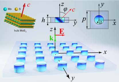
In what follows, we consider a metasurface composed of MoS2 anisotropic disk-shaped nanoparticles arranged in a two-dimensional array. The translation unit cell of this array is a square with the side size . The radius and height of the disks are and , respectively. The bulk MoS2 material is a thin-film structure, which is characterized by tensor-valued permittivity . The light wave in such a material behaves the same way as that in the uniaxial anisotropic crystal with the form birefringence property [11, 12]. In particular, it is a nonmagnetic ( = ) uniaxial anisotropic crystal whose anisotropy axis (-axis) is directed perpendicular to the plane of layers forming the MoS2 thin-film structure [9, 43]. For the sake of definiteness, we assume that the -axis of the crystal is tilted in the - plane and can change its orientation on the angle with respect to the -axis of the chosen Cartesian coordinate frame, where the -axis is also the rotation (axial symmetry) axis of the disks, as shown in Fig. 1. In the operating frequency range under study, material losses in the bulk MoS2 material are negligibly small (see Appendix A) and, therefore, we exclude them from our consideration. Without loss of generality, we assume that the particles are located in a homogeneous surrounding space (air). The trapped mode manifestation is related to the in-plane symmetry breaking of the metasurface unit cell. The substrate presence does not break the in-plane symmetry and has no significant influence on the effects discussed. Therefore, in order not to overload our study, we consider that the substrate is made of an air-like material . Accounting for the substrate can be performed later in the engineering implementation of the metasurface by adjusting the geometric parameters of the resonators used.
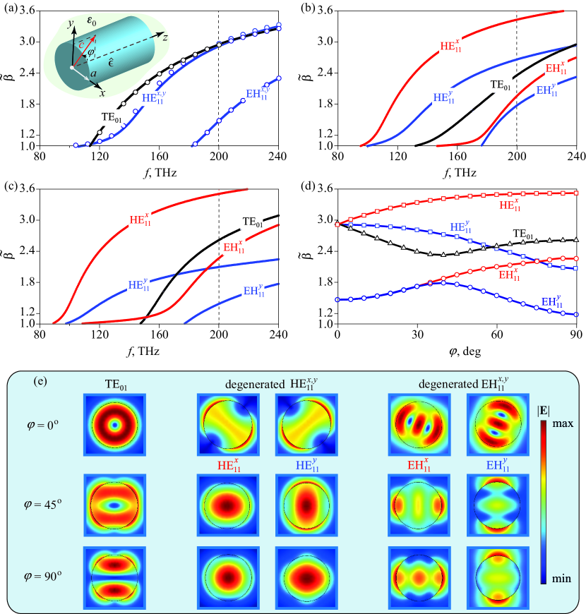
Initially, we perform an eigenwave analysis of the given metasurface. For our simulations, we use the RF module of the commercial COMSOL Multiphysics finite-element electromagnetic solver. In the solver, we construct one square unit cell of the metasurface imposing the Floquet-periodic boundary conditions on its sides to simulate the infinitely expanded two-dimensional array of nanoparticles. From the solutions found, we select those that correspond to the excitation of the lowest-order eigenwaves only. We classify these eigenwaves by considering the electromagnetic field configuration inside the resonator when the -axis tilt angle is zero and permittivity of the disk acquires the diagonal form . For the chosen geometric parameters of the resonators, the eigenwaves arise as the transverse electric TE01δ, and hybrid EH11δ and HE11δ modes, sequentially arranged with increasing frequency (this classification is based on the mode nomenclature of cylindrical dielectric waveguides, see Ref. [44]). In the subscripts of the mode abbreviations, the first index denotes the azimuthal variation of the fields, the second index denotes the order of variation of the field along the radial direction, and the third index denotes the order of variation of fields along the -direction. Since we do not fix the exact number of field variations along the -axis, we substitute the third index with the letter . In general, the characteristics of eigenwaves under study inherit the properties of the corresponding modes of an anisotropic nanowire derived in Appendix B.
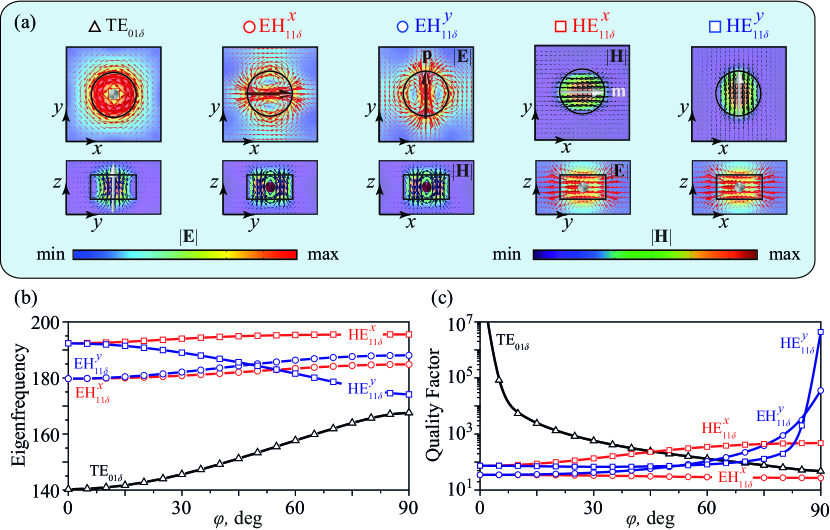
Moreover, as known from the theory of dielectric resonators [45], the TE01δ mode of an isolated cylindrical resonator radiates like a magnetic dipole oriented along its rotation axis (out-of-plane), whereas the EH11δ and HE11δ modes radiate like an electric dipole and magnetic dipole , respectively, oriented along the transverse direction (in-plane). Thus, each hybrid mode is complemented by its own degenerated state, depending on the direction in which the corresponding dipole moment is oriented, along either the -axis or the -axis in the chosen Cartesian coordinate frame. We distinguish these degenerated hybrid modes by adding the corresponding superscript or to the mode abbreviations. The appearance of all eigenwaves of our interest at the initial stage are collected in Fig. 2(a).
Among these eigenwaves, the field for the TE01δ mode is axisymmetric and thus has no azimuthal variation, whereas the fields of the hybrid modes EH and HE are azimuthally dependent. This property of the TE01δ mode leads to the appearance of conditions corresponding to the existence of the trapped mode in our lossless metasurface signifying that the corresponding eigenfrequency () is a purely real quantity ().
Further in our study, we vary the value of the tilt angle . When , there are off-diagonal components in the tensor , whereas when , the -axis is directed along the -axis, and permittivity of the disk becomes diagonal (see Appendix B). We track the change in the values of the real part of the eigenfrequency () and quality factor () of the selected eigenwaves. The corresponding results of our calculations are presented in Figs. 2(b) and 2(c), respectively. One can see that the hybrid EH and HE modes lose their degeneracy and split apart with a change in the tilt angle of the anisotropy axis, while the TE01δ mode does not. Moreover, the quality factor of the TE01δ mode changes from infinity to finite values undergoing a transformation from the trapped to a radiative state. Hereinafter, our task is to reveal the manifestation of these eigenwaves in the transmitted spectra of our metasurface.
III Spectral features
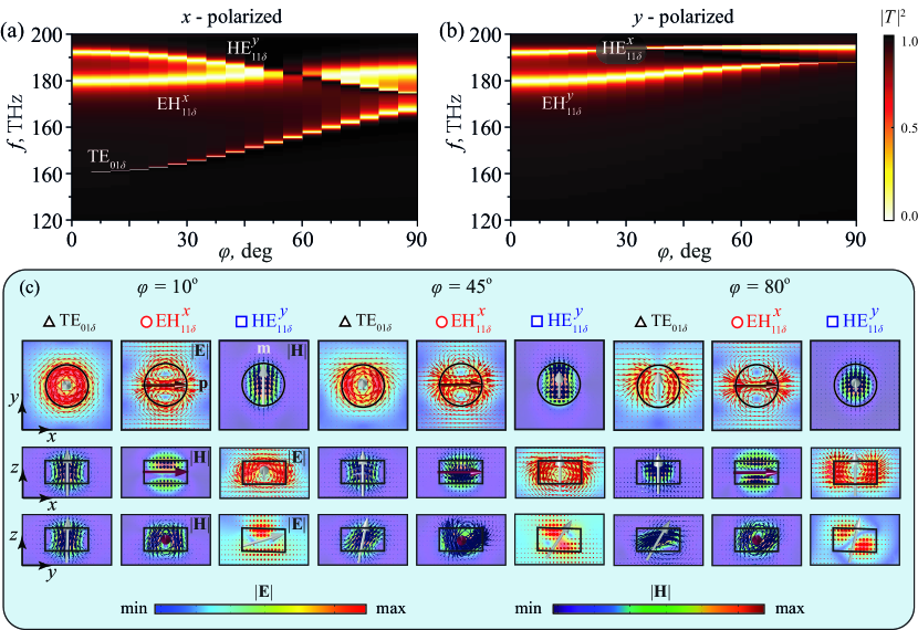
In this section, we reveal specific spectral features of the MoS2 metasurface caused by the material anisotropy. For this study we consider that the metasurface is illuminated by a plane electromagnetic wave under the normal incidence conditions () with the electric field polarized along either the -axis (, -polarization) or the -axis (, -polarization). In the framework of the RF module of the COMSOL Multiphysics solver, we dispose of the radiating and receiving ports above and below the metasurface, respectively. The port boundary conditions are placed on the interior boundaries of the perfectly matched layers, adjacent to the air domains. Perfectly matched layers on the top and bottom of the unit cell absorb the excited wave from the radiating port and prevent unwanted re-reflection inside the computational domain. The port boundary conditions automatically determine the reflection and transmission characteristics of the metasurface in terms of S-parameters. After simulation, we retrieve values of the transmission coefficient () as a function of the frequency and -axis tilt angle for two orthogonal polarizations of the incident wave. The results of our calculations are summarized in Figs. 3(a) and 3(b) for the -polarized and -polarized waves, respectively.
When , the metasurface is polarization-independent. In the frequency band of interest, there are two resonant states related to the excitation of the degenerated hybrid EH11δ and HE11δ modes. The identified resonances appear due to an existing electromagnetic coupling between the linearly polarized incident wave and transversely located electric and magnetic dipoles inherent to the corresponding eigenwaves. Since the TE01δ mode is axially symmetric with the corresponding magnetic dipole oriented orthogonally to the metasurface plane, the field of the incident wave does not interact with this mode and there is no corresponding resonance in the spectra of the transmitted wave.
Variation of the -axis tilt angle breaks the in-plane symmetry of the structure, resulting that the metasurface becomes to be polarization-dependent. Although the degeneracy for hybrid modes is lifted, their resonant positions on the frequency scale change a little compared to those of the degenerated modes that existed in the case. However, since the rotation of the anisotropy -axis is maintained in the - plane, noticeable changes are observed in the spectra of the -polarized wave. At a certain value of the -axis tilt angle (), the resonant frequencies of the EH and HE modes coincide, and with a further increase in , the resonances rearrange their order on the frequency scale. This mode-crossing effect is widely discussed in the context of the implementation of Huygens metasurfaces [26]. Moreover, the quality factor of the EH and HE resonances increases, since the electromagnetic coupling of the corresponding either electric or magnetic dipole with the field of the incident wave decreases.
Aside from the resonances related to the above-considered hybrid EH11δ and HE11δ modes which possess a good electromagnetic coupling with the field of the normally incident linearly polarized wave, in the frequency band of interest, an additional resonance arises in the transmitted spectra of the -polarized waves as soon as is nonzero. This resonance is related to the manifestation of the TE01δ mode. It appears as an alone-standing lowest frequency resonance whose quality factor decreases with increasing . This resonance acquires a peak-and-trough (Fano) profile as is typical for the trapped modes excitation [27, 36]. While the dip in curves corresponds to the maximum of reflection, the peak corresponds to the maximum of transmission. These extremes approach 0 and 1, respectively, since the material losses in the given metasurface are considered to be negligibly small.
To reveal the origin of changes in the emerging resonances, we plot the patterns of the electric and magnetic fields within the unit cell in three basic projections and show the orientation of the dipole moments and at the resonator center. These calculations are made for three different values of the -axis tilt angle . The results of our calculations are collected in Fig. 3(c). One can see that variation in the material anisotropy leads to a change in the slope of the dipole moment of the corresponding mode, thereby changing the degree of its electromagnetic coupling with the field of the incident wave. This mechanism is fully consistent with the behavior of trapped modes in resonators with perturbed unit cells [36, 46, 47] and the corresponding theory [37, 34, 40] can be adapted in this case. It is based on the scattering characteristics of a single anisotropic nanoparticle which we discussed in Appendix C.
IV Polarization features
Since the metasurface is composed of anisotropic particles, the polarization features of the metasurface at the resonant frequency of the trapped mode excitation should be elucidated. To this end, we study the transmission characteristics of our metasurface with respect to all polarization states of the incident wave for several values of the -axis tilt angle .
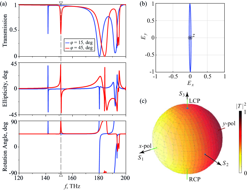
Figure 4(a) shows the corresponding frequency dependences of the transmission coefficient magnitude of circularly polarized waves, ellipticity angle (), and polarization azimuth () for the transmitted field. According to the definition of the Stokes parameters, we introduce the ellipticity so that the field is linearly polarized when , and for the left-handed circularly polarized (LCP) wave and for the right-handed circularly polarized (RCP) wave (note that in the latter cases the preferential azimuthal angle of the polarization ellipse becomes undefined). In all other cases (), the field is elliptically polarized. In the considered frequency band, the transmission coefficient magnitude of the given metasurface is the same for the LCP and RCP incident waves, whereas the transmitted field undergoes the rotation of its polarization ellipse at the resonant frequencies where it can change its polarization state. However, at the resonant frequency of the trapped mode excitation, the transmitted field remains to be almost linearly polarized regardless of the value of the -axis tilt angle . The corresponding polarization ellipse of the transmitted field for the trapped mode resonance is presented in Fig. 4(b), whose frequency is depicted in Fig. 4(a) by a vertical dashed line.
This polarization feature of the trapped mode is further confirmed by our mapping of the transmission coefficient magnitude of the metasurface for different polarization states onto the surface of the full Poincaré sphere as shown in Fig. 4(c). In our calculations, the electric field vector of the incident wave is defined by components and , where and [48, 49, 50]. The axes of the Poincaré sphere are labeled in terms of the Stokes parameters. Linearly polarized states are arranged along the sphere’s equator, while right-handed (RCP) and left-handed (LCP) circularly polarized waves are located at their north and south poles, respectively. All other points of the sphere depict elliptically polarized states of the incident wave. From the uniform color gradient of the sphere, it is easy to conclude that at the resonant frequency of the trapped mode excitation, there are the total reflection and total transmission of - and -polarized incident waves, respectively, while circularly polarized waves pass through the metasurface with half the amplitude of the incident wave.
V Conclusions
We have revealed the role of material anisotropy in the mechanism of the trapped mode excitation in a metasurface composed of MoS2 disk-shaped nanoparticles. Our study is based on the analysis of the properties of the three lowest-order modes of cylindrical resonators forming the metasurface. They are the axially symmetric TE01δ mode as well as the non-symmetric hybrid EH11δ and HE11δ modes.
When the anisotropy axis of the MoS2 material used for the disk-shaped particles fabrication coincides with the axis of their rotational symmetry, the hybrid EH11δ and HE11δ modes degenerate, whereas the TE01δ mode behaves like a trapped mode in the metasurface, possessing a purely real eigenfrequency. When the anisotropy axis is tilted, the hybrid EH11δ and HE11δ modes are split, and the TE01δ mode transforms into a radiative one, whose quality factor decreases with increasing the anisotropy tilt angle. It is shown how a change in the anisotropy tilt angle affects the orientation of vectors of the electric and magnetic dipole moments of the corresponding modes.
While we have considered a specific MoS2 material, the trapped mode excitation mechanism in metasurfaces composed of dielectric nanoparticles that we have demonstrated is general for both natural and artificial materials with uniaxial anisotropy. By performing control ability over the high-quality factor trapped modes in MoS2 metasurfaces by manipulating material anisotropy, we propose a platform for many important applications in light-matter interaction, nonlinear photonics, quantum optics, and spectroscopy.
Acknowledgements.
V.R.T. is grateful for the hospitality and support from Jilin University, China. A.B.E. thanks funding support from the Deutsche Forschungsgemeinschaft (DFG, German Research Foundation) under Germany’s Excellence Strategy within the Cluster of Excellence PhoenixD (EXC 2122, Project ID 390833453).Appendix A MoS2 relative permittivity
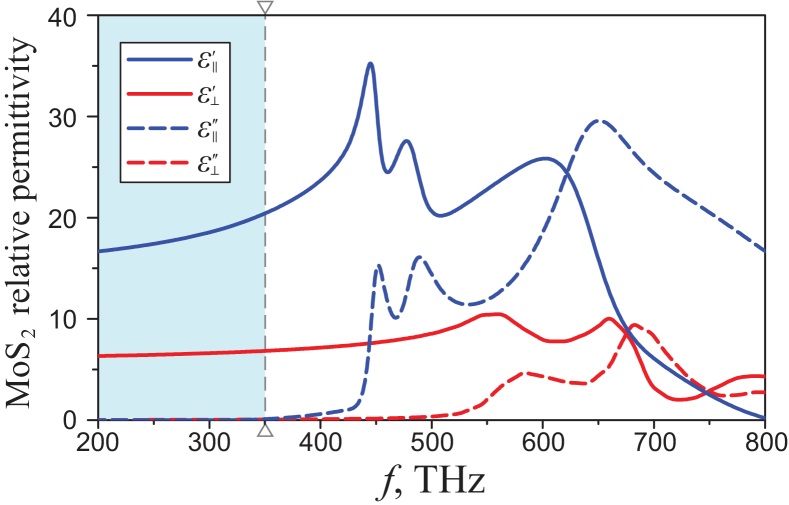
Dispersion characteristics of components of the tensor of the relative permittivity () of the MoS2 material are shown in Fig. 5. Since in our work, we focus on the spectral range within the third telecommunication window (), where negligibly weak dispersion exists (see the spectral region marked light blue), we adopt , , in all considered region.
Appendix B Lowest-order modes of an anisotropic nanowire
For reference, here we present dispersion features of three lowest-order modes (TE01, EH11, and HE11) of an anisotropic nanowire. The nanowire is made of a nonmagnetic material (MoS2) with the tensor-valued relative permittivity . The nanowire is disposed of in a surrounding medium with permittivity . The radius of the nanowire is . The symmetry axis of the nanowire coincides with the -axis of the Cartesian coordinate system [see the inset in Fig. 6(a)].
The optic -axis of the uniaxial crystalline MoS2 core of the nanowire is tilted in the --plane and makes an angle with the -axis. The full relative permittivity tensor of the nanowire core can be evaluated by using the rotation matrix
| (1) |
as follows
| (2) |
where and superscript denotes the matrix transposition operation.
As follows from Eq. (2), the permittivity of the nanowire can be defined in the diagonal form as and in two special cases when the -axis is directed along the -axis and the -axis, respectively. For the rest range , the tensor has nonzero off-diagonal components.
When the directions of the -axis and the -axis coincide, there is an analytical solution for the nanowire modes [51]. Generally, such an anisotropic nanowire supports an infinite set of the axially symmetric TEmn and TMmn modes as well as the non-symmetric hybrid EHmn and HEmn modes, whose dispersion equation can be expressed as [52]:
| (3) |
where, is the wavenumber in free space, and are the integer values known as the azimuthal and radial indices, respectively, is the longitudinal propagation constant, is the anisotropy parameter, and are the transverse propagation constants inside and outside the nanowire, respectively, and are the Bessel function of the first kind and the modified Bessel function of the second kind, and and are their derivatives with respect to the function argument.
A formal substitution of into Eq. (3) yields us two separate dispersion equations related to the transverse magnetic TM0n and transverse electric TE0n modes [see, the first and second multiplier on the left side of the dispersion equation (3), respectively], similarly to the case of a nanowire with an isotropic core [53].
In the general case of a uniaxial crystal core when the -axis does not coincide with the -axis, the propagation constants and field components can be determined numerically [54, 55, 56]. The calculated effective mode index and the electric field patterns of the lowest-order , , and modes propagated in the MoS2 nanowire are presented in Fig. 6 for different values of the -axis tilt angle . In particular, when the -axis is directed along the -axis, the results of our simulation are checked against those obtained from the analytical solution given by Eq. (3).
From Figs. 6(a)-6(c), one can conclude that when , the dispersion characteristic of the mode does not depend on the transverse polarization, that is, this mode does not split into the -polarized () and -polarized () components (see, also Refs. [57, 58]). Nevertheless, when , the axial symmetry of the electric field of the mode becomes violated, as shown in Fig. 6(e).
In turn, the dispersion characteristics of hybrid modes are more complex. Figure 6(a) shows that at , no modal birefringence phenomenon exists, it means that the hybrid and modes are degenerated as shown in Fig. 6(e), which is typical for uniaxial nanowires [57, 58].
In the range , the dispersion characteristics of hybrid and modes depend on the transverse polarization orientations, which leads to degeneracy lifting as presented in Fig. 6(e). Thus, the different polarizations of () and () modes have different dispersion relations and propagate like different modes, as shown in Figs. 6(b) and 6(c). For the chosen parameters of anisotropy, the effect of the -axis orientation is much stronger for the -polarized modes compared to the -polarized ones due to the fact that while [see, for clarity, Eq. (2)]. A similar feature has been reported previously for an anisotropic rectangular waveguide [55]. Besides, Fig. 6(d) indicates that difference between the -polarized and -polarized modes increases as the -axis tilt angle rises, and the difference between and modes is smaller than the difference between the and modes.
Appendix C Scattering cross-section of an anisotropic nanoparticle
For numerical simulations of the single particle scattering cross-section and the particle electric and magnetic dipole moments, we use the discrete dipole approximation (DDA) and the decomposed discrete dipole approximation (DDDA) methods [23]. The main idea of the DDA method consists in the replacement of the scattering object by a cubic lattice of electric point dipoles with known polarizability tensor . The corresponding dipole moment induced in each lattice point (with the radius vector ) is found by solving coupled dipole equations:
| (4) |
where is the electric field of the incident wave at the point , is the wavenumber in a vacuum, is the vacuum dielectric constant, is the Green tensor of the system without the particle, is the number of dipoles replacing the particle after the discretization procedure. For a MoS2 particle (disk), when the -axis of anisotropy is directed along the -axis in the chosen Cartesian coordinate frame (), the permittivity tensor is written as
| (5) |
and the polarizability tensor can be taken as
| (6) |
where is the volume of the discretization cell, is the relative permittivity of the surrounding medium. Here we assume that the particle is localized in a vacuum or in the air where . After the solution of Eqs. (4) and choosing the origin of the Cartesian coordinate system in the center of mass of the particle, the scattered electric field in the far-field zone and the spherical coordinates are written as
| (7) | |||||
where , is the unit vector directed to the observation point with spherical coordinate , is the distance to the observation point, and are the azimuthal and polar angles, respectively.
The scattering cross-section is calculated as
| (8) |
where and is the full solid angle and its differential.
In the DDDA, a discrete representation of the induced polarization inside the particle is obtained as
| (9) |
where is the Dirac delta function.
Using the relation , where is the field angular frequency, between the induced polarization and the induced electric current density and Eq. (9), the multipole moments of the particle can be calculated by applying the expressions from Ref. [59]. In this approach the multipole decomposition of the scattering cross-section is
where is vacuum permeability, and are the electric and magnetic dipole moments, and are the electric and magnetic quadrupole moments of the particle.
Note that from the practical point of view, it is convenient to rotate the disk under the fixed polarizability tensor (6) in the numerical simulation in order to change the anisotropic properties of the disk.
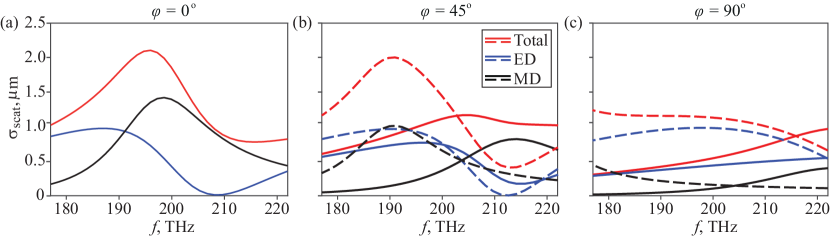
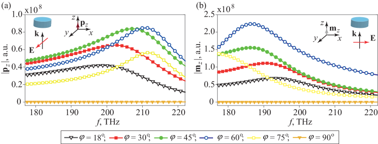
The results of our modeling of the cross-section characteristics of a single particle for several different values of the -axis tilt angle are shown in Fig. 7. First, one can see that the resonant response of the disk depends on both orientations of the MoS2 layers and irradiation conditions. Second, in the chosen frequency range, the resonant features are associated only with the resonant excitation of either the electric (ED) or magnetic (MD) dipole moments of the particle. Importantly, in the range, , the material anisotropy of the disk leads to the resonant excitation of the longitudinal (directed along the wave vector of the incident wave) components of the ED and MD dipole moments (Fig. 8). The excitation of () component is realized for the -polarized (-polarized) waves, respectively, and spectral positions of their extremes are completely correlated with the resonant features of the transmission spectra of the MoS2 metasurface presented in Figs. 3(a) and 3(b), respectively. This demonstrates that the discussed resonant states of the anisotropic metasurface are basically influenced by the anisotropy and modes of an individual dielectric resonator rather than by the electromagnetic coupling between them.
References
- Chen et al. [2016] H.-T. Chen, A. J. Taylor, and N. Yu, A review of metasurfaces: physics and applications, Rep. Prog. Phys. 79, 076401 (2016).
- Li et al. [2018] A. Li, S. Singh, and D. Sievenpiper, Metasurfaces and their applications, Nanophotonics 7, 989 (2018).
- Wang et al. [2018] G. Wang, A. Chernikov, M. M. Glazov, T. F. Heinz, X. Marie, T. Amand, and B. Urbaszek, Colloquium: Excitons in atomically thin transition metal dichalcogenides, Rev. Mod. Phys. 90, 021001 (2018).
- Verre et al. [2019] R. Verre, D. G. Baranov, B. Munkhbat, J. Cuadra, M. Käll, and T. Shegai, Transition metal dichalcogenide nanodisks as high-index dielectric Mie nanoresonators, Nat. Nanotechnol. 14, 679 (2019).
- Munkhbat et al. [2022] B. Munkhbat, B. Küçüköz, D. G. Baranov, T. J. Antosiewicz, and T. O. Shegai, Nanostructured transition metal dichalcogenide multilayers for advanced nanophotonics, Laser Photonics Rev. , 2200057 (2022).
- Xiao et al. [2020] S. Xiao, T. Wang, T. Liu, C. Zhou, X. Jiang, and J. Zhang, Active metamaterials and metadevices: a review, J. Phys. D: Appl. Phys. 53, 503002 (2020).
- Yan et al. [2015] X. Yan, L. Zhu, Y. Zhou, Y. E, L. Wang, and X. Xu, Dielectric property of MoS2 crystal in terahertz and visible regions, Appl. Opt. 54, 6732 (2015).
- Ermolaev et al. [2020] G. A. Ermolaev, Y. V. Stebunov, A. A. Vyshnevyy, D. E. Tatarkin, D. I. Yakubovsky, S. M. Novikov, D. G. Baranov, T. Shegai, A. Y. Nikitin, A. V. Arsenin, and V. S. Volkov, Broadband optical properties of monolayer and bulk MoS2, npj 2D Mater. Appl. 4, 21 (2020).
- Islam et al. [2021] K. M. Islam, R. Synowicki, T. Ismael, I. Oguntoye, N. Grinalds, and M. D. Escarra, In-plane and out-of-plane optical properties of monolayer, few-layer, and thin-film MoS2 from 190 to 1700 nm and their application in photonic device design, Adv. Photonics Res. 2, 2000180 (2021).
- Ermolaev et al. [2021] G. A. Ermolaev, D. V. Grudinin, Y. V. Stebunov, K. V. Voronin, V. G. Kravets, J. Duan, A. B. Mazitov, G. I. Tselikov, A. Bylinkin, D. I. Yakubovsky, S. M. Novikov, D. G. Baranov, A. Y. Nikitin, I. A. Kruglov, T. Shegai, P. Alonso-González, A. N. Grigorenko, A. V. Arsenin, K. S. Novoselov, and V. S. Volkov, Giant optical anisotropy in transition metal dichalcogenides for next-generation photonics, Nat. Commun. 12, 854 (2021).
- Born and Wolf [1959] M. Born and E. Wolf, Principles of Optics: Electromagnetic Theory of Propagation, Interference and Diffraction of Light (Pergamon Press Ltd., 1959) Chap. 14.
- Yariv and Yeh [1984] A. Yariv and P. Yeh, Optical Waves in Crystals: Propagation and Control of Laser Radiation (Wiley, 1984) Chap. 6.
- Jayasekara et al. [2016] C. Jayasekara, M. Premaratne, S. D. Gunapala, and M. I. Stockman, MoS2 spaser, J. Appl. Phys. 119, 133101 (2016).
- Ren et al. [2021] Q. Ren, F. Feng, X. Yao, Q. Xu, M. Xin, Z. Lan, J. You, X. Xiao, and W. E. I. Sha, Multiplexing-oriented plasmon-MoS2 hybrid metasurfaces driven by nonlinear quasi bound states in the continuum, Opt. Express 29, 5384 (2021).
- Wang et al. [2022] X. Wang, J. Xin, Q. Ren, H. Cai, J. Han, C. Tian, P. Zhang, L. Jiang, Z. Lan, J. You, and W. E. I. Sha, Plasmon hybridization induced by quasi bound state in the continuum of graphene metasurfaces oriented for high-accuracy polarization-insensitive two-dimensional sensors, Chin. Opt. Lett. 20, 042201 (2022).
- Srivastava et al. [2017] Y. K. Srivastava, A. Chaturvedi, M. Manjappa, A. Kumar, G. Dayal, C. Kloc, and R. Singh, MoS2 for ultrafast all-optical switching and modulation of THz Fano metaphotonic devices, Adv. Opt. Mater. 5, 1700762 (2017).
- Bucher et al. [2019] T. Bucher, A. Vaskin, R. Mupparapu, F. J. F. Löchner, A. George, K. E. Chong, S. Fasold, C. Neumann, D.-Y. Choi, F. Eilenberger, F. Setzpfandt, Y. S. Kivshar, T. Pertsch, A. Turchanin, and I. Staude, Tailoring photoluminescence from MoS2 monolayers by Mie-resonant metasurfaces, ACS Photonics 6, 1002 (2019).
- Muhammad et al. [2021] N. Muhammad, Y. Chen, C.-W. Qiu, and G. P. Wang, Optical bound states in continuum in MoS2-based metasurface for directional light emission, Nano Lett. 21, 967 (2021).
- Li et al. [2022] H. Li, G. Wei, H. Zhou, H. Xiao, M. Qin, S. Xia, and F. Wu, Polarization-independent near-infrared superabsorption in transition metal dichalcogenide Huygens metasurfaces by degenerate critical coupling, Phys. Rev. B 105, 165305 (2022).
- Zhang et al. [2022] Y. Zhang, D. Chen, W. Ma, S. You, J. Zhang, M. Fan, and C. Zhou, Active optical modulation of quasi-BICs in Si–VO2 hybrid metasurfaces, Opt. Lett. 47, 5517 (2022).
- Evlyukhin et al. [2010] A. B. Evlyukhin, C. Reinhardt, A. Seidel, B. S. Luk’yanchuk, and B. N. Chichkov, Optical response features of Si-nanoparticle arrays, Phys. Rev. B 82, 045404 (2010).
- Kuznetsov et al. [2016] A. I. Kuznetsov, A. E. Miroshnichenko, M. L. Brongersma, Y. S. Kivshar, and B. Luk’yanchuk, Optically resonant dielectric nanostructures, Science 354, aag2472 (2016).
- Evlyukhin et al. [2011] A. B. Evlyukhin, C. Reinhardt, and B. N. Chichkov, Multipole light scattering by nonspherical nanoparticles in the discrete dipole approximation, Phys. Rev. B 84, 235429 (2011).
- Khromova et al. [2016] I. Khromova, P. Kužel, I. Brener, J. L. Reno, U.-C. Chung Seu, C. Elissalde, M. Maglione, P. Mounaix, and O. Mitrofanov, Splitting of magnetic dipole modes in anisotropic TiO2 micro-spheres, Laser Photon. Rev. 10, 681 (2016).
- Razmjooei et al. [2021] N. Razmjooei, Y. H. Ko, F. A. Simlan, and R. Magnusson, Resonant reflection by microsphere arrays with AR-quenched Mie scattering, Opt. Express 29, 19183 (2021).
- Decker et al. [2015] M. Decker, I. Staude, M. Falkner, J. Dominguez, D. N. Neshev, I. Brener, T. Pertsch, and Y. S. Kivshar, High-efficiency dielectric Huygens’ surfaces, Adv. Opt. Mater. 3, 813 (2015).
- Fedotov et al. [2007] V. A. Fedotov, M. Rose, S. L. Prosvirnin, N. Papasimakis, and N. I. Zheludev, Sharp trapped-mode resonances in planar metamaterials with a broken structural symmetry, Phys. Rev. Lett. 99, 147401 (2007).
- Koshelev et al. [2018] K. Koshelev, S. Lepeshov, M. Liu, A. Bogdanov, and Y. Kivshar, Asymmetric metasurfaces with high- resonances governed by bound states in the continuum, Phys. Rev. Lett. 121, 193903 (2018).
- Khardikov et al. [2010] V. V. Khardikov, E. O. Iarko, and S. L. Prosvirnin, Trapping of light by metal arrays, J. Opt. 12, 045102 (2010).
- Kupriianov et al. [2019] A. S. Kupriianov, Y. Xu, A. Sayanskiy, V. Dmitriev, Y. S. Kivshar, and V. R. Tuz, Metasurface engineering through bound states in the continuum, Phys. Rev. Applied 12, 014024 (2019).
- Xiao et al. [2022] S. Xiao, M. Qin, J. Duan, F. Wu, and T. Liu, Polarization-controlled dynamically switchable high-harmonic generation from all-dielectric metasurfaces governed by dual bound states in the continuum, Phys. Rev. B 105, 195440 (2022).
- He et al. [2018] Y. He, G. Guo, T. Feng, Y. Xu, and A. E. Miroshnichenko, Toroidal dipole bound states in the continuum, Phys. Rev. B 98, 161112 (2018).
- van Hoof et al. [2021] N. J. van Hoof, D. R. Abujetas, S. E. Ter Huurne, F. Verdelli, G. C. Timmermans, J. A. Sánchez-Gil, and J. G. Rivas, Unveiling the symmetry protection of bound states in the continuum with terahertz near-field imaging, ACS Photonics 8, 3010 (2021).
- Evlyukhin et al. [2020] A. B. Evlyukhin, V. R. Tuz, V. S. Volkov, and B. N. Chichkov, Bianisotropy for light trapping in all-dielectric metasurfaces, Phys. Rev. B 101, 205415 (2020).
- Tsilipakos et al. [2021] O. Tsilipakos, L. Maiolo, F. Maita, R. Beccherelli, M. Kafesaki, E. E. Kriezis, T. V. Yioultsis, and D. C. Zografopoulos, Experimental demonstration of ultrathin broken-symmetry metasurfaces with controllably sharp resonant response, Appl. Phys. Lett. 119, 231601 (2021).
- Tuz et al. [2018] V. R. Tuz, V. V. Khardikov, A. S. Kupriianov, K. L. Domina, S. Xu, H. Wang, and H.-B. Sun, High-quality trapped modes in all-dielectric metamaterials, Opt. Express 26, 2905 (2018).
- Yu et al. [2019] P. Yu, A. S. Kupriianov, V. Dmitriev, and V. R. Tuz, All-dielectric metasurfaces with trapped modes: Group-theoretical description, J. Appl. Phys. 125, 143101 (2019).
- Bi et al. [2021] K. Bi, Q. Wang, J. Xu, L. Chen, C. Lan, and M. Lei, All-dielectric metamaterial fabrication techniques, Adv. Opt. Mater. 9, 2001474 (2021).
- Evlyukhin et al. [2021] A. B. Evlyukhin, M. A. Poleva, A. V. Prokhorov, K. V. Baryshnikova, A. E. Miroshnichenko, and B. N. Chichkov, Polarization switching between electric and magnetic quasi-trapped modes in bianisotropic all-dielectric metasurfaces, Laser Photonics Rev. 15, 2100206 (2021).
- Prokhorov et al. [2022a] A. V. Prokhorov, A. V. Shesterikov, M. Y. Gubin, V. S. Volkov, and A. B. Evlyukhin, Quasitrapped modes in metasurfaces of anisotropic nanoparticles for absorption and polarization control in the telecom wavelength range, Phys. Rev. B 106, 035412 (2022a).
- Prokhorov et al. [2022b] A. V. Prokhorov, P. D. Terekhov, M. Y. Gubin, A. V. Shesterikov, X. Ni, V. R. Tuz, and A. B. Evlyukhin, Resonant light trapping via lattice-induced multipole coupling in symmetrical metasurfaces, ACS Photonics 9, 3869 (2022b).
- Qin et al. [2022] M. Qin, J. Duan, S. Xiao, W. Liu, T. Yu, T. Wang, and Q. Liao, Strong coupling between excitons and quasi-bound states in the continuum in the bulk transition metal dichalcogenides, arXiv preprint arXiv:2209.00416 (2022).
- Ushkov et al. [2022] A. A. Ushkov, G. A. Ermolaev, A. A. Vyshnevyy, D. G. Baranov, A. V. Arsenin, and V. S. Volkov, Anapole states and scattering deflection effects in anisotropic van der Waals nanoparticles, Phys. Rev. B 106, 195302 (2022).
- Snitzer [1961] E. Snitzer, Cylindrical dielectric waveguide modes, J. Opt. Soc. Am. 51, 491 (1961).
- Mongia and Bhartia [1994] R. K. Mongia and P. Bhartia, Dielectric resonator antennas—a review and general design relations for resonant frequency and bandwidth, Int. J. RF Microw. Comput. Aided Eng. 4, 230 (1994).
- Sayanskiy et al. [2019] A. Sayanskiy, A. S. Kupriianov, S. Xu, P. Kapitanova, V. Dmitriev, V. V. Khardikov, and V. R. Tuz, Controlling high- trapped modes in polarization-insensitive all-dielectric metasurfaces, Phys. Rev. B 99, 085306 (2019).
- Vaity et al. [2022a] P. Vaity, H. Gupta, A. Kala, S. Dutta Gupta, Y. S. Kivshar, V. R. Tuz, and V. G. Achanta, Polarization-independent quasibound states in the continuum, Adv. Photonics Res. 3, 2100144 (2022a).
- Tuz et al. [2020] V. R. Tuz, P. Yu, V. Dmitriev, and Y. S. Kivshar, Magnetic dipole ordering in resonant dielectric metasurfaces, Phys. Rev. Applied 13, 044003 (2020).
- Tuz and Evlyukhin [2021] V. R. Tuz and A. B. Evlyukhin, Polarization-independent anapole response of a trimer-based dielectric metasurface, Nanophotonics 10, 4373 (2021).
- Vaity et al. [2022b] P. Vaity, H. Gupta, A. Kala, S. Dutta Gupta, Y. S. Kivshar, V. R. Tuz, and V. Gopal Achanta, Polarization-independent quasi-bound states in the continuum, Adv. Photonics Res. 3, 2100144 (2022b).
- Tonning [1982] A. Tonning, Circularly symmetric optical waveguide with strong anisotropy, IEEE Trans. Microwave Theory Techn. 30, 790 (1982).
- Paul and Shevgaonkar [1981] D. K. Paul and R. K. Shevgaonkar, Multimode propagation in anisotropic optical waveguides, Radio Sci. 16, 525 (1981).
- Yu et al. [2018] P. Yu, V. I. Fesenko, and V. R. Tuz, Dispersion features of complex waves in a graphene-coated semiconductor nanowire, Nanophotonics 7, 925 (2018).
- Vandenbulcke and Lagasse [1976] P. Vandenbulcke and P. E. Lagasse, Eigenmode analysis of anisotropic optical fibers or integrated optical waveguides, Electron. Lett. 12, 120 (1976).
- Koshiba et al. [1986] M. Koshiba, K. Hayata, and M. Suzuki, Finite-element solution of anisotropic waveguides with arbitrary tensor permittivity, J. Lightwave Technol. 4, 121 (1986).
- Bagatskaya et al. [2005] O. V. Bagatskaya, V. I. Fesenko, and S. N. Shulga, Electric field lines in a rectangular waveguide with an inhomogeneous anisotropic insert, Telecommun. Radio Eng. 63, 1 (2005).
- Dai and Jen [1991] J. D. Dai and C. K. Jen, Analysis of cladded uniaxial single-crystal fibers, J. Opt. Soc. Am. A 8, 2021 (1991).
- Dai et al. [1992] J. D. Dai, C. A. S. de Oliveira, and C. K. Jen, Dispersion characteristics of cladded biaxial optical fibers, J. Opt. Soc. Am. A 9, 1564 (1992).
- Evlyukhin and Chichkov [2019] A. B. Evlyukhin and B. N. Chichkov, Multipole decompositions for directional light scattering, Phys. Rev. B 100, 125415 (2019).