Conformal Metasurfaces for Recovering Dynamic Blockage in Vehicular Systems
Abstract
Intelligent reflecting surfaces (IRS) will represent a key technology in the upcoming sixth-generation (6G) communication networks to extend the network coverage and overcome link blockage. Research on IRS is expected to take a giant leap in the coming years to address the current technological limitations, mainly regarding the IRS re-configuration in highly dynamic scenarios, such as vehicle-to-vehicle (V2V) ones. This paper proposes a fully passive and low-cost solution based on pre-configured IRS to be lodged on the vehicle’s body, which does not require any signaling for re-configuration. However, conventional IRS are planar array and cannot fit with most vehicles’ silhouettes. Hence, the proposed design targets conformal surfaces (C-IRS) with an arbitrary shape. In particular, this paper reveals the first experimental findings on the realization of C-IRS operating at 26 GHz and measurements in anechoic chamber, which validate the analytical derivations. To demonstrate the benefits of the proposed solution, numerical simulations in a V2V scenario show that, when the percentage of vehicles equipping a C-IRS increases, the communication becomes more robust to vehicles’ blockage and the average end-to-end SNR is enhanced up to 25 dB.
Index Terms:
Conformal metasurface, IRS, V2V, 6GI Introduction
The 5G network rollouts are in full swing globally, with standardization advancing to address new market verticals [1]. While optimization of early 5G devices and networks is an ongoing process, the research community is already focusing on what 6G networks will be. 6G networks are expected to use higher frequencies in the millimeter-wave (mmWave - GHz), sub-THz, and THz bands [2]. However, because of the harsher radio wave propagation, i.e., higher path and penetration losses compared to currently deployed system at sub-6 GHz [3], high frequency radio links are particularly vulnerable to blockage, especially when the mobility of users increases (e.g., in vehicle-to-everything (V2X) scenarios [4]), resulting in limited communication range and unreliable links. In vehicle-to-vehicle (V2V) scenarios, the main source of blockage is another vehicle interposing between the transmitting vehicle (Tx) and the receiving vehicle (Rx), which can cause a power loss of up to dB at GHz, degrading with Tx-Rx distance and traffic intensity [4].
6G network optimization will rely upon relays and smart metasurfaces to mitigate the blockage. Relay-based solutions represent one possibility, either using relays of opportunity [5] or macro-diversity at infrastructure level [6]. However, the latter pushing for network densification increases the cost of deployment and complexity. Differently, smart metasurfaces, a.k.a. reconfigurable intelligent surfaces (RIS) or intelligent reflecting surfaces (IRS) [7], are an emerging technology capable of manipulating an incoming electromagnetic (EM) field to control the reflection/refraction direction. Incorporating RIS/IRS into wireless networks has been advocated as a revolutionary means to transform any passive wireless propagation environment into an active controllable one, i.e., enabling the smart radio environment (SRE) [8]. Herein, we refer to RIS when the amplitude and phase of each element can be set in real-time [9] and to IRS when it is pre-configured and not tunable [10]. Although the RIS and IRS terminologies are often used interchangeably in literature, we herein stress this distinction to distinguish between fully passive surfaces (IRS) and nearly passive ones (RIS). Moreover, RIS are more flexible in dynamic environments but require dedicated control signaling, while IRS are cheaper and need no power supply and control signaling.
RISs have been largely investigated in literature as a technology that improves the average capacity per unit area [7] and addresses the blockage issue in vehicular networks. Referring to blockage management, in [11], the authors propose a RIS-assisted handover scheme using deep reinforcement learning to mitigate the blockage in a cellular scenario. In the considered setting, the base station computes the RIS configuration for each cluster of users based on the observed channels. The proposed approach does not explicitly solve a non-convex optimization problem for RIS configuration as in [12], yet, it still requires additional signaling overhead, which might be unsuitable for high mobility V2V scenario. Moreover, the real-time RIS reconfiguration is still an open issue, although some works consider a finite phase set at each RIS element to decrease the control overhead [13]. Most works consider the perfect channel state information (CSI) available at the RIS, or they assume slowly varying CSI scenarios [14]. However, for V2V links, the CSI outdates rapidly [15], making the state-of-the-art solutions inefficient or even impractical. A novel hybrid RIS is considered in [16] to reduce the signaling overhead, where the RIS can sense the received power and self-configure. However, the hybrid solution requires additional hardware and power costs. Conversely, IRS-based solutions provide a fully passive alternative to RIS when the deployment cost is prohibitive, or the incidence/reflection angles are not a-priori known and cannot be estimated accurately.
In this regard, in our recent work [17], we introduced a novel arrangement, which consists of mounting metasurfaces on next generation vehicles’ sides, e.g., connected automated vehicles (CAVs), such that to mitigate the blockage affection by non-CAVs. However, since the vehicle shape is not planar, the standard RIS/IRS solution is not appropriate. Hence, we have generalized the configuration problem of RIS/IRS by considering a conformal design for any arbitrary 3D metasurface (C-RIS/C-IRS), and we derived the related analytical phase configuration. This paper extends previous works with the first experimental findings on the fabrication of a C-IRS (pre-configured) operating at 26 GHz and the corresponding radiation pattern measurements in anechoic chamber. The observed outcomes validate the analytical results (both lossless and lossy simulations) and thereby open up the opportunity for large-scale deployment of this technology since the production and maintenance cost is much more competitive than any other solution. As an additional result, we show the trend of the average SNR in a multi-lane highway scenario where a variable percentage of CAVs is equipped with C-RIS/C-IRS on their sides. Compared to conventional V2V systems exploiting only the direct link, C-IRS provide a beneficial SNR gain that grows with traffic density and CAVs percentage (up to dB), as well as C-RIS, that represent the benchmark and the upper performance bound (up to dB of SNR gain). These results further justify the adoption of conformal metasurfaces for 6G vehicular networks.
Organization: The remainder of the paper is organized as follows: Section II outlines the system and channel model, and describes the proposed C-IRS design, Section III shows the practical realization and testing of the C-IRS while Section IV validates the C-IRS benefits in a V2V network. Finally, conclusions are in Section V.
Notation: Bold upper- and lower-case letters describe matrices and column vectors. Matrix transposition and hermitian are indicated respectively as and . extracts the trace of . is the diagonal matrix given by vector . is the identity matrix of size . With we denote a multi-variate circularly complex Gaussian random variable with mean and covariance . is the expectation operator, while and stand for the set of real and complex numbers, respectively. is the Kronecker delta.
II System Model and C-IRS Design
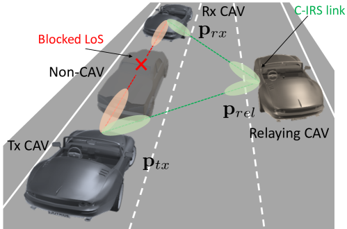
We consider the V2V network in Fig. 1 representing a scenario with multiple lanes. A fraction of the vehicles are connected autonomous vehicles (CAVs), equipped with a mmWave/sub-THz uniform linear array (ULA) with antenna elements, and two C-IRS on both vehicle’s sides. The position of Tx and Rx CAVs’ antenna is and , respectively, defined in the global coordinate system. Similarly, the candidate relaying CAV is located in , where identifies the position of the C-IRS phase center. The global coordinate system is such that the cars move along direction , the cross-motion axis is , and denotes the vertical direction.
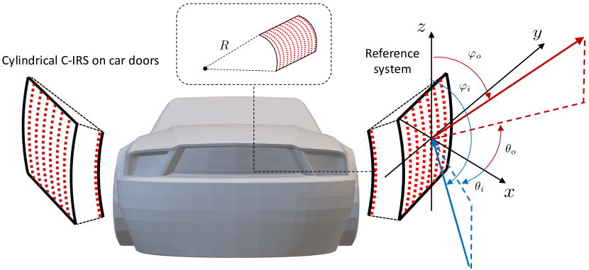
Herein, the shape of each C-IRS along the vehicles’ sides is approximated by a cylinder section with a given radius and length . Note that the cylindrical approximation allows to obtain close-form expressions of the phase pattern configuration, that generalize the results of planar IRS, which can be obtained for . Each C-IRS has elements deployed along the conformal coordinate (i.e., vehicle height ), and elements along the cylindrical direction (i.e., vehicle length ). The equipment is sketched in Fig. 2. The position of the -th C-IRS element, for and , is , the relative 3D displacement of the -th element is: , and . is the angular position in local cylindrical coordinates of the -th row, while and are the elements’ spacing along the vertical and horizontal directions, respectively. The C-IRS area is , where is the angular sector spanned by the C-IRS. According to the size of common car doors [18], for m and m, and selecting in the range provides a reasonable closed-form shape approximation.
II-A Signal Model
Let the input-output relation of the MIMO communication system between Tx and Rx CAVs be
| (1) |
where is the complex Tx symbol of power , is the additive white Gaussian noise at the Rx antennas , are the Tx and Rx beamforming vectors and
| (2) |
is the spatially-sparse MIMO channel. The latter is the sum of the direct Tx-Rx channel and reflection channels via as many relaying CAVs equipped with C-IRS [19]. In this setting, is the channel from the Tx to the -th C-IRS, the one from the -th C-IRS and
| (3) |
is the diagonal phase-configuration matrix at each C-IRS. With (3), we assume for simplicity a lossless C-IRS made with a fully reflecting material with no mutual coupling between elements. The direct Tx-Rx channel is modeled under plane wave approximation as [2]
| (4) |
where (i) denotes the complex amplitude of the direct path, modelled as in [20]; (ii) , are the Tx and Rx array response vectors, function of the angles of arrival (AoAs) and departure (AoDs) of the direct path, respectively and (for azimuth and elevation), (iv) and are the Tx and Rx single-antenna gains, respectively [21].
The model in (4) applies also to the reflection channels and whenever the Tx-relay and relay-Rx distance is in excess of few tens of meters. If this is the case, i.e. far-field condition, (4) holds with proper scattering amplitudes and local AoAs and AoDs on/from the -th C-IRS, routinely called angles of incidence (AoI) and reflection (AoR), denoted with and respectively. Local AoI/AoR can be expressed as function of the global ones and knowing the shape of the C-IRS.
II-B Design of C-IRS for Vehicular Applications
To lodge a C-IRS on the sides of any vehicle, it must match the shape of the vehicle’s side silhouette, possibly thin (see Section III) and thus takes into account the surface’s profile.
Let us consider the C-IRS local reference system in Fig. 2. The goal is to design the C-IRS phase to reflect the impinging radio signal from direction towards . Leveraging on the generalized Snell’s law of reflection [22], the C-IRS phase configuration across the elements is reported in (5), for an arbitrarily shaped C-IRS.
| (5) |
According to (5), the C-IRS phase configuration requires the perfect knowledge of AoIs and AoRs . However, they both quickly vary in a vehicular scenario and thus require a real-time reconfiguration, which is signaling intensive and might be unfeasible in practice. Hence, the proposed solution consists of realizing a C-IRS that behaves as an EM flat mirror, which can be obtained by setting a pre-configuration that matches the typical AoIs and AoRs in vehicular networks. As detailed in our recent work [17], the elevation AoI/AoR ( and ) are approximately Gaussian distributed around deg with a typical standard deviation of deg, while the distribution of azimuth AoI/AoR ( and ) is wider and monotonically increases toward deg.
Therefore, we reasonably impose deg and leave the azimuth as a free design parameter . By substituting the C-IRS elements positions in (5) we obtain:
| (6) |
which depends only on the shape of the C-IRS along the conformal dimension, i.e., on the curvature radius and angular position of the elements , as well as on the operating azimuth angle and wavelength . Notice that the phase gradient is non-zero along the curved dimension only, and that every other C-IRS shape can be accounted for by (5).
III Realization of C-IRS
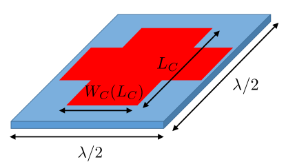
C-IRS realization can be carried out in several ways, either using the concept of true metasurface [23], with an ideally continuum phase distribution, or using the concept of reflectarray [24], in which the phase distribution is sampled and each element of the reflectarray must introduce the phase required at the corresponding sampling point. The former approach provides a good degree of flexibility in the phase pattern design at the price of being complex while the latter one is by far the most used one for its simplicity and its better potential for massive and low cost production. The C-IRS design is practically ruled by the design of the master element. Reflectarray design discussed in this work is based on planar metallic resonating elements printed on a low cost flexible substrate. The design of the specific element must account for some potentially critical issues, such as tolerances in the realization, bandwidth, polarization (single or double) and ohmic efficiency. Optimal design is achieved by a combined effect of thickness of substrate material and shape of the planar element. Cross-shaped elements have been used here in the design (Fig. 3). These represent an excellent compromise between all requirements, because the parameters that control the cross ( and in Fig. 3) can be optimized in terms of tolerances, bandwidth and phase value required by the selected element. In particular, it was found that by a suitable selection of these two parameters, the cross outperforms the simple square element in a double polarization system, both in terms of bandwidth and tolerances in fabrication. The final design uses different crosses with different values of and at different position, as a result of a global optimization of the required phases. The high resolution pattern was fabricated with a traditional photolithographic technique. Lower resolution pattern was prepared using a toner-reactive metal foil, hot laminated over a transfer paper printed in a standard laser printer. We specifically accounted in the design for robustness to small lithographic errors in the realization. This requirement is achieved by designing the slope of the phase curve in the neighborhood of the resonant frequency. Excessive steepness in the phase curve introduces excessive sensitivity to small errors in the lithographic printing process and small differences of the permittivity of the substrate with respect to nominal value. Metal patterns have been printed by an inkjet printer. A quite good adhesion to the substrate was found even for very small thickness of the metallization. The ink adhere to the substrate and it forms tiny bubbles. Tolerances in the printing process do have an impact on the final design, but they did not severely impact the final performances.
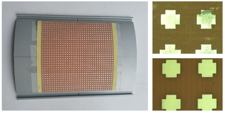
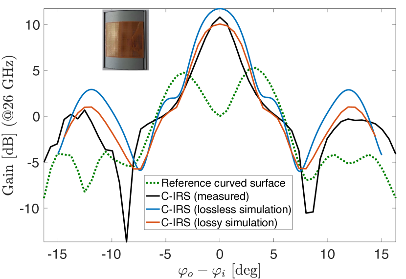
As a manufacturing benchmark, we designed a C-IRS aiming to compensate a curved surface with a curvature radius of cm and working at GHz. The C-IRS in the application must provide a focused beam in the incidence plane where the curvature lies (see Fig. 2), thereby compensating the spreading of the wavefield due to the curvature of the surface. This specific design represents a good benchmark because here the radius of curvature is rather small for vehicles’ door and the required element phases spans the complete set of angles from to deg. The C-IRS occupies an area of cm2 and elements are present on the curved surface. A view of the C-IRS is shown in Fig. 4, together with a closeup of part of the patterned surface in two realizations.
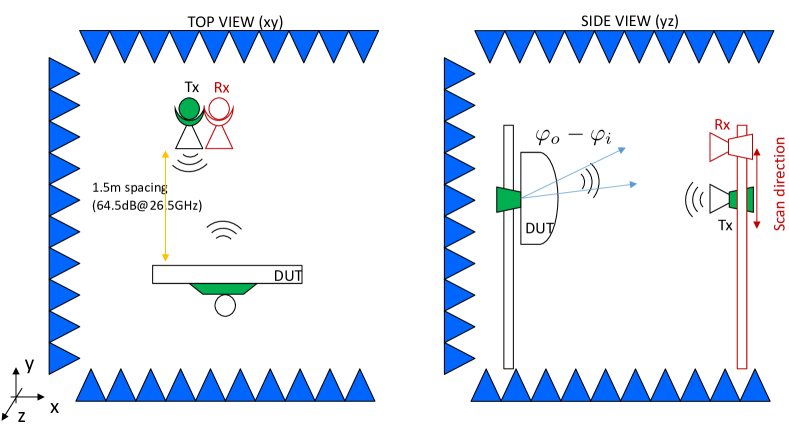
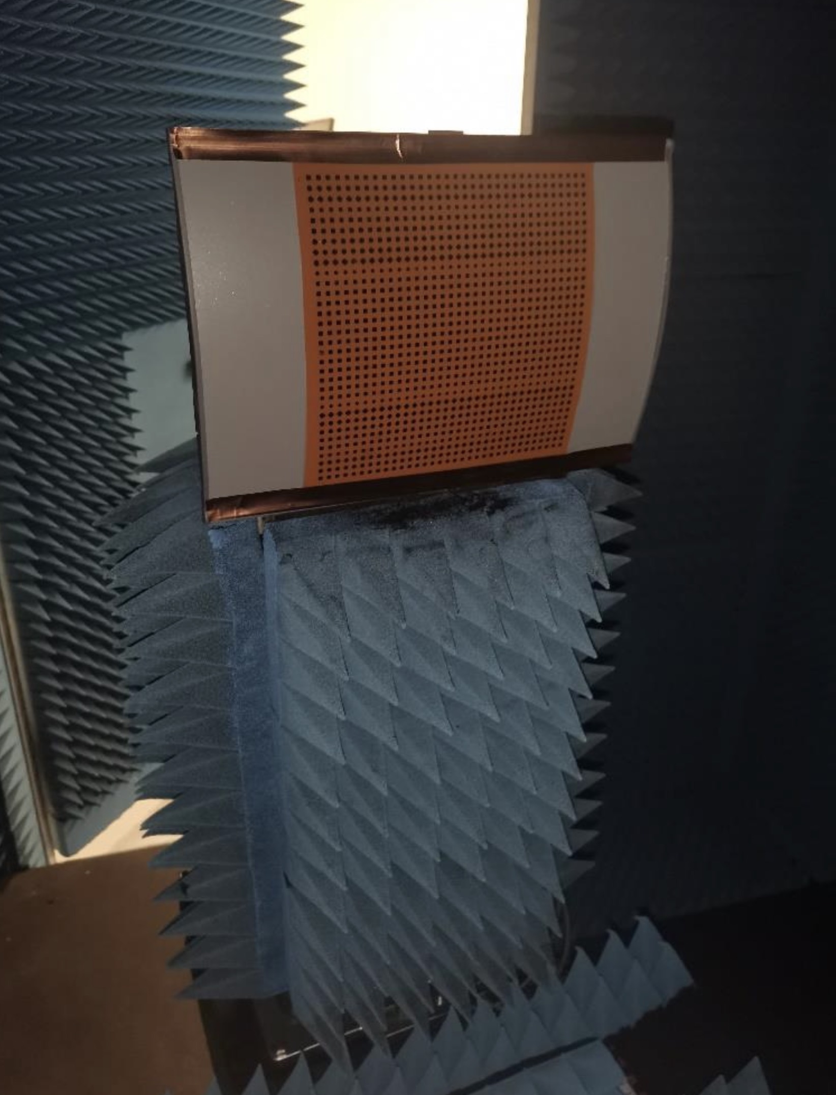
The realized structure has been measured in anechoic chamber. A transmitting antenna is placed at 1.5 m from the surface and the receiving antenna at the same distance is moved horizontally to collect the scattered field over a 1 m extension, corresponding to about deg from broadside. An accurate positioning of the reference target and the patterned target allowed to compare the two scattered field in the same conditions, so as to verify the focusing capabilities. For clarity, a picture of the measurement setup is shown in Fig. 6 and a detail of the C-IRS mounted in the chamber is in Fig. 5. It must be noted that we are still in Fresnel region of the scattered field, but even so, the widely different behavior of the simple curved surface with respect to the patterned one is clearly visible in the results in Fig. 7. This compares the scattered field of the plain curved surface (labelled reference curved surface) with the one of the C-IRS as a function of the position of the receiving antenna, that is represented by angle . The incidence angle is . The gain obtained by the C-IRS in terms of focusing of the scattered field is clearly visible and it amounts to about 10 dB. In the comparison, a very good agreement between simulated data and measured data can be observed. Thanks to the robustness in the design, tolerances and possible difference of the material permittivity with respect to nominal value () play a minor role. The comparison in Fig. 7 is also useful to assess the performances in terms of ohmic efficiency. EM simulations with and without losses indicate that the impact of losses is relatively small and the advantage of patterned C-IRS is still very clear in the figures.
IV Simulation Results in V2V Networks
The goal is now to evaluate the advantages of C-IRS lodged on CAV doors in a multi-lane scenario of m length with lanes, each of m width. Numerical analysis is y evaluating the average SNR. All vehicles in the scenario are modelled with an occupation region of m3 and randomly distributed according to a point Poisson process with parameter (i.e., traffic density) cars/km per lane. Simulation parameters are in Table I. We consider a variable percentage of CAVs in the scenario, as expected within the transition towards autonomous driving. While CAVs are equipped with C-IRS, other vehicles are not.
Let us assume that Tx and Rx CAVs know their positions, namely and , as well as the position of other CAVs in the scenario. In the present simulations, we assume for simplicity Tx and Rx located on the same lane at distance m. When C-IRS are designed for specular reflection, a candidate relaying CAV can only be located halfway between Tx and Rx, in , where is set of allowed relay positions, i.e., a spatial region of size centered in . While is the highway width, is chosen to be two times the length of the C-IRS, i.e., . The best beam pair between Tx and Rx , to be used in (1), is chosen within dynamic codebooks and , built upon the knowledge of the candidate relaying CAVs within . Thus,
| (7) |
where , i.e., the cardinality is the number of candidate relays plus the direct link. The choice in (7) is therefore dictated by the maximum SNR at the Rx via all the possible links (direct and relayed). Notice that is ruled by both the traffic density and the CAV percentage . Fixing and the geometry of the scenario, a blockage event on a single Tx-relay-Rx link happens when at least one of the two Tx-relay and relay-Rx links is blocked. The blockage probability is therefore the probability that all the Tx-relay-Rx links are jointly blocked. The presence of one or more vehicles interposing between Tx-Rx, Tx-relay and relay-Rx is accounted as additional power loss on the link budget compared to the usual free-space loss, as indicated in [4].
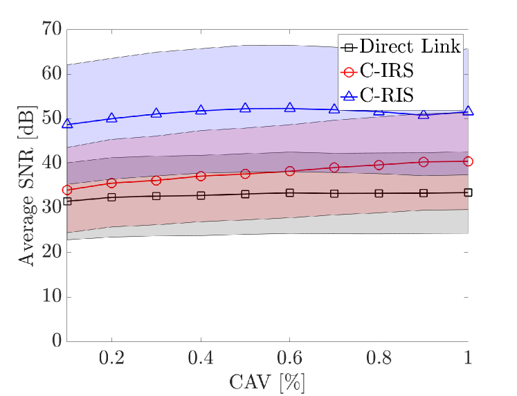
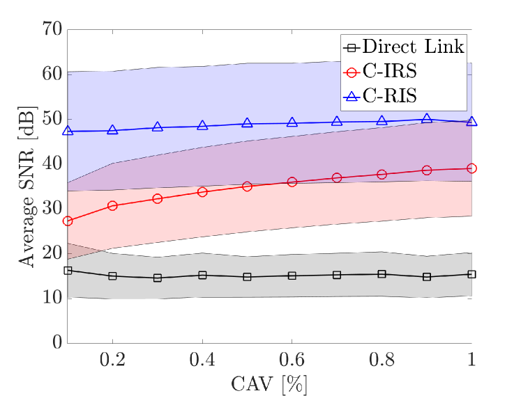
Figure 8 shows the trend of the average SNR varying the CAVs percentage , for two different traffic densities, cars/km (Fig. 8a, low-traffic) and cars/km (Fig. 8b, medium-to-high traffic). The shaded areas represent the confidence interval defined by the standard deviation. We compare the performance of a V2V system relying only on the direct link (black curves) to the proposed C-IRS-assisted one (red curves). To mere comparison, we also report the case in which CAVs are equipped with C-RIS (blue curves) [17], i.e., they can dynamically configure the RIS phase to enable arbitrary reflections by assuming the perfect knowledge of CAVs positions. In this latter case, the candidate relays can be searched within all the scenario, thus providing the upper performance bound. Compared to a conventional V2V link, the C-IRS-assisted one provides a remarkable SNR gain that increases with and . In particular, for cars/km the SNR gain is dB, while for cars/km it amounts to dB, for . For increasing , moreover, C-IRS almost fill the gap provided by C-RIS: this is a direct consequence of the increase in potential relaying CAVs equipped with C-IRS. For C-RIS, instead, it is sufficient to find one relay within the scenario to enable a strong reflection link (the RIS gain is approx dB, at least in favourable conditions, i.e., perfect phase configuration), thus the performance are substantially independent from and . These results justify the research effort in vehicle-lodged metasurfaces for 6G V2V networks, and particularly toward inexpensive and pre-configured C-IRS, that do not need dedicated control signaling and power supply.
| Parameter | Symbol | Value(s) |
|---|---|---|
| Carrier frequency | GHz | |
| Number of Tx/Rx antennas | ||
| Tx-Rx distance | m | |
| Number of C-IRS elements | ||
| C-IRS element spacing | ||
| C-IRS curvature radius | m | |
| C-IRS configuration param. | deg | |
| Transmitted power | dBm | |
| Noise power | dBm |
V Conclusion
This paper proposes the usage of C-IRS, properly lodged on CAVs’ sides, to mitigate the blockage affection in V2V networks without involving any active relaying. We analytically provide the C-IRS phase configuration under a cylindrical approximation of cars’ doors, and validate the derived models by physical realization and testing in anechoic chamber of a C-IRS operating at 26 GHz frequency. The measured reflection pattern along the the curved plane of the C-IRS shows a perfect match with the predicted one by both lossless and lossy EM simulations. In addition, numerical results in a multi-lane highway V2V scenario show the SNR gain when equipping CAVs with C-IRS, increasing with both CAV’s percentage and traffic density, attaining a remarkable 20 dB compared to the usage of direct V2V link only.
Acknowledgment
This work has been carried out within the Huawei-Politecnico di Milano Joint Research Lab.
References
- [1] 3GPP, “Study on channel model for frequencies from 0.5 to 100 ghz (release 16, tr 22186),” 2019.
- [2] T. S. Rappaport, Y. Xing, O. Kanhere, S. Ju, A. Madanayake, S. Mandal, A. Alkhateeb, and G. C. Trichopoulos, “Wireless communications and applications above 100 ghz: Opportunities and challenges for 6g and beyond,” IEEE access, vol. 7, pp. 78 729–78 757, 2019.
- [3] F. Jameel, S. Wyne, S. J. Nawaz, and Z. Chang, “Propagation channels for mmwave vehicular communications: State-of-the-art and future research directions,” IEEE Wireless Communications, vol. 26, no. 1, pp. 144–150, 2018.
- [4] K. Dong, M. Mizmizi, D. Tagliaferri, and U. Spagnolini, “Vehicular blockage modelling and performance analysis for mmwave v2v communications,” arXiv preprint arXiv:2110.10576, 2021.
- [5] F. Linsalata, S. Mura, M. Mizmizi, M. Magarini, P. Wang, M. N. Khormuji, A. Perotti, and U. Spagnolini, “Los-map construction for proactive relay of opportunity selection in 6g v2x systems,” arXiv preprint arXiv:2111.07804, 2021.
- [6] I. K. Jain, R. Kumar, and S. S. Panwar, “The impact of mobile blockers on millimeter wave cellular systems,” IEEE Journal on Selected Areas in Communications, vol. 37, no. 4, pp. 854–868, 2019.
- [7] Y. Liu, X. Liu, X. Mu, T. Hou, J. Xu, M. Di Renzo, and N. Al-Dhahir, “Reconfigurable intelligent surfaces: Principles and opportunities,” IEEE Communications Surveys Tutorials, vol. 23, no. 3, pp. 1546–1577, 2021.
- [8] Y. Zhang, J. Zhang, M. Di Renzo, H. Xiao, and B. Ai, “Performance analysis of ris-aided systems with practical phase shift and amplitude response,” IEEE Transactions on Vehicular Technology, 2021.
- [9] S. Abeywickrama, R. Zhang, Q. Wu, and C. Yuen, “Intelligent reflecting surface: Practical phase shift model and beamforming optimization,” IEEE Transactions on Communications, vol. 68, no. 9, pp. 5849–5863, 2020.
- [10] G. Oliveri, P. Rocca, M. Salucci, and A. Massa, “Holographic smart em skins for advanced beam power shaping in next generation wireless environments,” arXiv preprint arXiv:2106.10932, 2021.
- [11] L. Jiao, P. Wang, A. Alipour-Fanid, H. Zeng, and K. Zeng, “Enabling efficient blockage-aware handover in ris-assisted mmwave cellular networks,” IEEE Transactions on Wireless Communications, pp. 1–1, 2021.
- [12] Y. Chen, Y. Wang, J. Zhang, and M. Di Renzo, “Qos-driven spectrum sharing for reconfigurable intelligent surfaces (riss) aided vehicular networks,” IEEE Transactions on Wireless Communications, 2021.
- [13] J. Yin, Q. Wu, Q. Lou, H. Wang, Z. N. Chen, and W. Hong, “Single-beam 1 bit reflective metasurface using prephased unit cells for normally incident plane waves,” IEEE Transactions on Antennas and Propagation, vol. 68, no. 7, pp. 5496–5504, 2020.
- [14] G. Zhou, C. Pan, H. Ren, K. Wang, M. D. Renzo, and A. Nallanathan, “Robust beamforming design for intelligent reflecting surface aided miso communication systems,” IEEE Wireless Communications Letters, vol. 9, no. 10, pp. 1658–1662, 2020.
- [15] M. H. C. Garcia, A. Molina-Galan, M. Boban, J. Gozalvez, B. Coll-Perales, T. Şahin, and A. Kousaridas, “A tutorial on 5g nr v2x communications,” arXiv preprint arXiv:2102.04538, 2021.
- [16] I. Alamzadeh, G. C. Alexandropoulos, N. Shlezinger, and M. F. Imani, “A reconfigurable intelligent surface with integrated sensing capability,” Scientific Reports, vol. 11, no. 1, p. 20737, 2021. [Online]. Available: https://doi.org/10.1038/s41598-021-99722-x
- [17] M. Mizmizi, R. Aghazadeh Ayoubi, D. Tagliaferri, K. Dong, G. G. Gentili, and U. Spagnolini, “Conformal metasurfaces: a novel solution for vehicular communications,” arXiv e-prints, pp. arXiv–2201, 2022.
- [18] L. Fan, J. Xiaomin, H. Gang, and G. Jing, “A novel shape-adjustable surface and its applications in car design,” Journal of Applied Science, vol. 9, no. 2339, pp. 1–20, 2019.
- [19] E. Björnson and L. Sanguinetti, “Rayleigh fading modeling and channel hardening for reconfigurable intelligent surfaces,” IEEE Wireless Communications Letters, vol. 10, no. 4, pp. 830–834, 2021.
- [20] 3rd Generation Partnership Project (3GPP), “Study on evaluation methodology of new vehicle-to-everything (v2x) use cases for lte and nr (v15.3.0, release 15),” vol. TR 37.885, Tech. Rep., 2019.06.
- [21] S. W. Ellingson, “Path loss in reconfigurable intelligent surface-enabled channels,” in 2021 IEEE 32nd Annual International Symposium on Personal, Indoor and Mobile Radio Communications (PIMRC), 2021, pp. 829–835.
- [22] S. R. Biswas, C. E. Gutiérrez, A. Nemilentsau, I.-H. Lee, S.-H. Oh, P. Avouris, and T. Low, “Tunable graphene metasurface reflectarray for cloaking, illusion, and focusing,” Phys. Rev. Applied, vol. 9, p. 034021, Mar 2018. [Online]. Available: https://link.aps.org/doi/10.1103/PhysRevApplied.9.034021
- [23] C. L. Holloway, E. F. Kuester, J. A. Gordon, J. O’Hara, J. Booth, and D. R. Smith, “An Overview of the Theory and Applications of Metasurfaces: The Two-Dimensional Equivalents of Metamaterials,” IEEE Antennas and Propagation Magazine, vol. 54, no. 2, pp. 10–35, 2012.
- [24] M. H. Dahri, M. I. Abbasi, M. H. Jamaluddin, and M. R. Kamarudin, “A Review of High Gain and High Efficiency Reflectarrays for 5G Communications,” IEEE Access, vol. 6, pp. 5973–5985, 2018.