Over-the-Air Beamforming with Reconfigurable Intelligent Surfaces
Abstract
Reconfigurable intelligent surface (RIS)-empowered communication is a revolutionary technology that enables to manipulate wireless propagation environment via smartly controllable low-cost reflecting surfaces. However, in order to outperform conventional communication systems, an RIS-aided system with solely passive reflection requires an extremely large surface. To meet this challenge, the concept of active RIS, which performs simultaneous amplification and reflection on the incident signal at the expense of additional power consumption, has been recently introduced. In this paper, deploying an active RIS, we propose a novel beamforming concept, over-the-air beamforming, for RIS-aided multi-user multiple-input single-output (MISO) transmission schemes without requiring any pre/post signal processing hardware designs at the transmitter and receiver sides. In the proposed over-the-air beamforming-based transmission scheme, the reflection coefficients of the active RIS elements are customized to maximize the sum-rate gain. To tackle this issue, first, a non-convex quadratically constrained quadratic programming (QCQP) problem is formulated. Then, using semidefinite relaxation (SDR) approach, this optimization problem is converted to a convex feasibility problem, which is efficiently solved using the CVX optimization toolbox. Moreover, taking inspiration from this beamforming technique, a novel high-rate receive index modulation (IM) scheme with a low-complexity sub-optimal detector is developed. Through comprehensive simulation results, the sum-rate and bit error rate (BER) performance of the proposed designs are investigated.
\helveticabold1 Keywords:
Reconfigurable intelligent surface (RIS), active RIS, over-the-air beamforming, multi-user (MU) transmission, index modulation (IM).
2 Introduction
Customizing propagation environment via reconfigurable intelligent surfaces (RISs) has been an appealing field for wireless communication and provides novel insights about future generation networks. These light-weight and cost-effective electronic elements have been regarded as a game changer technology for conventional communication systems with power-hungry and complex hardware designs (Basar et al., 2019). Particularly, RISs are programmable metasurfaces that are capable of configuring the propagation environment in a desired manner via performing reflection, amplification, absorption, refraction, etc. (Di Renzo et al., 2020). However, the most of the extant literature particularly focuses on the application of the RIS with passive reflection in various emerging systems (Basar et al., 2019; Di Renzo et al., 2020; Gong et al., 2020).
In the early studies, a passive RIS is deployed for enhancing transmit signal quality of single-antenna (Basar, 2019) and multiple-antenna systems (Yu et al., 2019; Zhang et al., 2020; Yigit et al., 2020). In subsequent studies, an RIS is facilitated for numerous objectives of single-user and multi-user systems, such as promoting energy-efficiency (Huang et al., 2019; Björnson et al., 2019), enhancing error performance (Ye et al., 2020; Ferreira et al., 2020) and improving achievable rate (Zhang and Zhang, 2020; Perović et al., 2021; Di et al., 2020). Further, novel deep learning-based solutions for passive RIS designs (Taha et al., 2021; Kundu and McKay, 2021) and security enhanced RIS-aided communication systems (Shen et al., 2019), (Almohamad et al., 2020; Dong and Wang, 2020) are proposed. On the other hand, index modulation (IM) principle, which is emerged as a promising energy-efficient solution to meet high data-rate demand of future wireless networks (Basar et al., 2017), is beneficially amalgamated into the RIS-empowered communication (Basar, 2020; Li et al., 2021). Considering more conventional IM designs, (Li et al., 2021; Basar, 2020) put forward RIS-aided receive IM schemes, which maximize the signal powers of the target receive antennas. However, in (Guo et al., 2020; Lin et al., 2020), novel reflection modulation (RM) concepts, which innovatively utilize the RISs for delivering additional information, are proposed. Above all, main limitation of the aforementioned studies is the lack of comprehensive practical insights on considered system configurations. Towards this aim, a low-complexity joint beamforming optimization that considers the effect of hardware impairments on the performance of RIS-aided multi-antenna systems are investigated in (Shen et al., 2021), different RIS prototypes are introduced for real-time implementations in (Dai et al., 2020; Tang et al., 2020), and realistic physical channel models for millimeter-wave (mmWave) (Basar et al., 2021) and sub- GHz bands (Kilinc et al., 2021; Yigit et al., 2021a) are presented. Nevertheless, the abovementioned system designs suffer from the multiplicative path attenuation due to the inherent drawback of the RIS-aided designs, and achieve negligible performance gains over the conventional communication systems.
Recently, to tackle above challenges, the concept of active RIS, which performs simultaneous amplification and reflection on the incident wave, is introduced in (Zhang et al., 2021; Long et al., 2021). Accordingly, the magnitudes and the phases of the reflecting elements of the active RIS, which are equipped with additional power amplifiers, are properly tuned in a customized way (Basar and Poor, 2021). Therefore, at the cost of additional power consumption, active RIS-aided systems are capable of achieving enhanced capacity gains (Long et al., 2021). In a recent study on designing active RISs, via leveraging power amplifiers and radio frequency (RF) chains (Nguyen et al., 2022), dynamic and fixed hybrid RIS architectures are constructed. Further, for improving the data rate, a new RM design, which employs the sub-groups of a hybrid RIS as information transfer units, is presented in (Yigit et al., 2021b). In follow-up studies, the concept of the active RIS is deployed for beamforming optimization of the RIS-aided multi-user systems (Gao et al., 2022; Thanh Nguyen et al., 2022). Above all, the potential of the active RIS-aided systems for achieving enormous performance gains will enable to develop promising solutions for future research.
In this study, unlike the conventional precoding techniques that employ power-hungry and hardware-complex devices (Sohrabi and Yu, 2016), for RIS-aided multi-user downlink transmission systems, we propose a novel over-the-air beamforming technique with the aid of an active RIS to exploit its capability of manipulating the magnitude of the incident wave. In other words, the main motivation of the over-the-air beamforming scheme is to simplify the transmitter and receiver ends of the overall network while transferring inter-user interference elimination tasks completely to an active RIS. Therefore, this paper proposes two novel over-the-air beamforming schemes that mitigate the burden of signal processing on the transmitter and receiver sides. In the proposed over-the-air beamforming-based transmission scheme, it is assumed that a multi-antenna transmitter serves single-antenna users through an active RIS without utilizing any other signal processing tasks at the transmitter and the receiver sides. Then, the reflection coefficients of the active RIS is properly adjusted to maximize the sum-rate of the overall system. Moreover, taking inspiration from this over-the-air beamforming concept, a new receive IM scheme that transmits additional information bits to specify the index of the effective received antenna is also proposed. Contrary to the traditional receive IM systems (Luo et al., 2021; Zhang et al., 2013), in the proposed system, since no precoding is applied at the transmitter, the reflection coefficients of the active RIS are rectified to steer the incident signal into the intended receive antenna. On the other hand, since the receive IM scheme benefits from the multi-antenna transmission at the user side and IM system design at the receiver side, it shows the favourable features of both, such as high spectral efficiency and improved performance. In these proposed over-the-air downlink beamforming and over-the-air uplink receive IM schemes, to optimize reflection coefficients of the active RISs, two distinct semidefinite relaxation (SDR)-based optimization problems are formulated, which can be effectively solved through the CVX convex optimization toolbox (Grant and Boyd, 2008). Furthermore, the achievable rate and bit error rate (BER) performance of the proposed over-the-air beamforming-based transmission schemes are investigated through extensive computer simulations.
The rest of the paper is organized as follows. In Section 2, after giving a short review of the conventional zero-forcing (ZF) precoding, we introduce the system model of the proposed over-the-air beamforming-based multi-user multi-antenna transmission scheme. In Section 3, the over-the-air beamforming-based receive IM scheme and its low-complexity receiver detection are introduced. Section 4 provides the achievable rate and BER results of the proposed over-the-air beamforming based transmission systems, and the conclusions are drawn in Section 5.
Notations: Throughout this paper, matrices and vectors are denoted by boldface upper-case and boldface lower-case letters, respectively. represents transpose and denotes the Hermitian transpose operation. , , and are stand for rank, trace and diagonalization of a matrix, respectively. Absolute value of a scalar is denoted by , while represents the Hadamard product. is used for expectation and represents a complex Gaussian random variable with mean and variance. stands for the identity matrix, while denotes big notation.
3 Over-the-Air Beamforming with RIS
In this section, after a review of conventional transmit precoding, the over-the-air beamforming concept is introduced for multi-user multiple-input single-output (MISO) downlink transmission systems.
3.1 Conventional Transmit Precoding
Considering a typical multi-user downlink transmission system without an RIS, a base station (BS) transmitter (T) with antennas is assumed to perform ZF precoding to alleviate interference between single-antenna users (Spencer et al., 2004). Let represents the channel matrix of the direct links between the T and the users, where is modeled as independent Rayleigh fading channel matrix with and is the corresponding path attenuation, which is calculated as , where is the reference path attenuation at a distance of meter (m) and is the distance between T and the users. Then, the received signal of the -th user (), for , becomes
| (1) |
where being an -ary phase shift keying (PSK) signal to be transmitted over the -th transmit antenna. Here, is the -th row of the channel matrix corresponding to the channel vector between T-, is the precoding vector for and is the static noise at . Therefore, the signal-to-interference-plus-noise-ratio (SINR) at can be calculated as
| (2) |
Moreover, the overall transmit ZF precoding matrix, exploiting the perfect channel state information (CSI), can be obtained as (Spencer et al., 2004)
| (3) |
where and is a scaling constant to meet the total power constraint , such that .
3.2 System Model of Over-the-Air Beamforming with RIS
In this subsection, after a brief introduction of the active RIS concept, the system model of the over-the-air beamforming-based multi-user transmission system is introduced.
3.2.1 Active RIS
The principal drawback of RIS-aided communication systems is the inherent multiplicative path attenuation along the RIS-aided indirect link, which is hardly compensated by the RIS with passive reflecting elements (Zhang et al., 2021; Basar and Poor, 2021). Therefore, to overcome this challenge, an RIS architecture with active reflecting elements that enable to configure both the magnitude and phase of the incident wave at the expense of an additional power consumption, is recently proposed (Zhang et al., 2021; Khoshafa et al., 2021). Therefore, unlike the passive RISs, the active RISs reflect incident signal with amplification via employing additional power circuitry. Although the active reflecting elements have a similar capability of amplifying the incident signal as in the full-duplex amplify-and-forward (AF) relays, their hardware constructions are completely different from each other. While the AF relays embody a circuitry for amplification in their hardware constructions and they are also externally equipped with high power-consuming RF chains to transmit and receive signals (Wu and Zhang, 2019), the active reflecting elements employ reflective-type power amplifiers to simultaneously rectify the magnitude and phase of the incident wave (Zhang et al., 2021).

3.2.2 System Model
An overwhelming literature on passive RIS-aided multi-user transmission deploys the RIS as a passive beamformer after a preprocessing is conducted at the transmitter (Wu and Zhang, 2019; Yan et al., 2020). However, in the proposed over-the-air beamforming concept, to avoid power-hungry hardware constructions at the transmitter and the users, exploiting simultaneous amplification and reflection capabilities of the active reflecting elements, both active and passive beamforming are carried out at an active RIS. Accordingly, the reflection coefficients of the active RIS are optimized to maximize the achievable rate of the overall system.
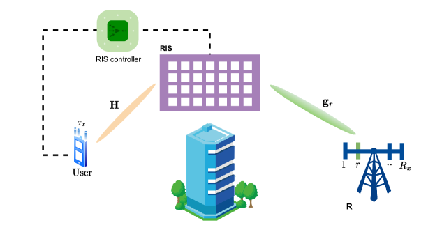
As given in Figure 1, in the proposed scheme, the direct transmission links between T with antennas and single-antenna users are neglected due to obstacles, thus, the communication is established through an active RIS with reflecting elements. In the proposed over-the-air beamforming-based multi-user transmission, it is assumed that T and the users have the perfect CSI about T-RIS and RIS-users channels, which is conveyed to a smart RIS controller via a feedback control link (Wu and Zhang, 2019). Moreover, at the transmitter side, without requiring any additional signal processing approaches for interference mitigation, the overall signal is conveyed to the users through the RIS. Hence, unlike the traditional beamforming techniques that employ complex and power-hungry signal processing hardware (Sohrabi and Yu, 2016; El Ayach et al., 2014), the RIS is designed as a beamformer to alleviate multi-user interference by adjusting the amplitude and phase of each reflecting element. Towards this aim, the RIS elements are assumed to be equipped with additional power circuitry to modify both the magnitude and the phase of the incident signal (Zhang et al., 2021; Nguyen et al., 2022; Yigit et al., 2021b). Furthermore, in the proposed system, since all transmit antennas simultaneously convey their own -PSK modulated signals, a spectral efficiency of [bits/s/Hz] is achieved.
Let us assume that the channels between T-RIS are presented by the matrix and represents the vector of channel coefficients between the RIS and , where and correspond to path attenuation between T-RIS and RIS- links for , respectively. Here, for and being the corresponding distances, using a well-known distance-dependent model, the path attenuations are obtained as and , where and are the path loss exponents at T-RIS and RIS-, respectively. In the proposed system, the matrix and the vector are both modeled as Rayleigh fading channels, whose each element is an independent and identically distributed (i.i.d.) Gaussian random variable with . In addition, the RIS architecture that is equipped with additional power circuitry to operate as an active RIS (Zhang et al., 2021), is represented in a diagonal matrix , where and being the amplitude and phase of the -th reflecting element for . It is worth noting that since active reflecting elements are capable to amplify the incident signal, the magnitude of each reflecting element is greater than unity, i.e., . Therefore, for being the number of the transmit antennas allocated to each user and being the signal vector to be transmitted to the -th user, the received signal at is obtained as
| (4) |
where and . Here, is the transmit power dissipated to the -th user, the vector represents the thermal noise generated from power amplifier circuits of active reflecting elements (Zhang et al., 2021) and is the static noise term at , where and for and being the corresponding noise variances of dynamic and static noise figures, respectively. Moreover, at the user side, since the received superposed signal at (4) includes the targeted and interference signals, it can be rewritten as
| (5) |
where and is the channel matrix between the transmit antenna group dedicated to -th user and the RIS. At this point, the SINR at can be calculated as:
| (6) |
Accordingly, the sum-rate of the overall system becomes:
| (7) |
Then, to maximize this sum-rate, the reflection coefficients of the active RIS elements are optimized. In what follows, the corresponding problem formulation and the proposed solution are presented.
3.3 Problem Formulation and Proposed Solution
In the over-the-air beamforming-based multi-user transmission scheme, interference cancellation is performed at the RIS without employing any additional integrated high-cost signal processing circuitry, such as multiple RF chains, either at T or user sides. For this purpose, the reflection coefficients of the RIS are adjusted to maximize the SINR of the intended . Therefore, to deal with this problem, the following QCQP problem is formulated
| (8) | |||
| (9) | |||
| (10) |
where is the minimum SINR requirement of , , and is the maximum reflection power introduced by the active reflecting elements. Please note that for the over-the-air beamforming-based multi-user systems, the total power is the sum of power dissipated at the transmitter () and the RIS (), that is , while for the conventional transmission without RIS, denotes to total power consumed at the transmitter. Then, using the Cauchy-Schwarz inequality, the constraint in (10) can be rewritten as
| (11) |
Therefore, since the problem (P1) is non-convex and it is difficult to obtain an optimal solution, we resort to the SDR technique and define new variables , and . In light of these, the SINR of the -th user in (6) can be rewritten as
| (12) |
where , and , while for being a vector consisting the non-zero diagonal elements of the reflection matrix , i.e., (Zhang, 2017; Ye et al., 2020). Therefore, the maximization problem (P1) is equivalently defined as
| (13) | |||
| (14) | |||
| (15) |
Here, is a positive semidefine matrix and . However, since the rank-one constraint is non-convex, we remove this constraint and reformulate (P2) as a convex feasibility problem as follows
| (16) | |||
| (17) | |||
| (18) |
Finally, through the existing solvers of CVX toolbox (Grant and Boyd, 2008), a feasible solution of (P3) satisfying the inequality constraints in (17) and (18) is obtained. However, after the relaxation, the optimal solution of (P3) cannot always ensure the rank-one solution. Therefore, for being the optimal solution of the problem (P3), using the eigenvalue decomposition of , the estimated is sub-optimally obtained as
| (19) |
where is a Gaussian random vector with , where is a unitary matrix of eigenvectors and is a diagonal matrix of eigenvalues. Then, after determining optimized reflection matrix, the RIS performs over-the-air beamforming in order to alleviate the user interference.
4 Over-the-Air Receive Index Modulation
In this section, the proposed over-the-air beamforming concept is adopted to a novel receive IM transmission scheme. Considering the over-the-air beamforming approach given in Section II, a single-user uplink transmission of an active RIS-aided IM transmission system is developed.
4.1 System Model of Over-the-Air Receive IM
As given in Figure 2, in the proposed IM system, due to presence of the obstacles over the direct links, a multi-antenna user communicates with an -antenna receiver (R) through an RIS with reflecting elements. Besides, an RIS controller is attached to the RIS that exchanges the information through a feedback control link. In the proposed system, considering the IM transmission principle (Basar, 2020), an over-the-air receive IM scheme is developed. Unlike traditional receive IM schemes (Stavridis et al., 2012; Zhang et al., 2013; Luo et al., 2021) that deploy transmit precoding techniques via high-cost hardware devices for preprocessing the transmit signal before its transmission, the proposed receive IM scheme employs the RIS as a signal processing unit and apply an over-the-air beamforming at the RIS. In the over-the-air receive IM scheme, at the user side, the conventional multi-antenna transmission is considered. Moreover, in order to attain higher data rates, extra information bits are conveyed via indicating the active receive antenna index. Therefore, the incoming information bits are used to determine the modulated -PSK symbols for each of the available transmit antennas, as well as to specify the active receive antenna index, one out of receive antennas. Therefore, the spectral efficiency achieved by this novel receive IM scheme is calculated as
| (20) |
In this system, the information of the active receive antenna index and perfect channel knowledge of user-RIS and RIS-R links is shared by the user to the RIS through the smart controller. Then, the reflection coefficient of the RIS elements are adjusted to ensure that the target receive antenna has the strongest received signal power. In other words, by the means of active reflecting elements, the RIS acts as a kind of digital beamformer and steers the overall signal along the desired receive antenna direction.
Let the multi-path fading channels between user-RIS and RIS-R links are modeled as the independent Rayleigh fading channels, which are denoted by the channel matrices of and , respectively, where is the -th row of the the channel matrix corresponding to the channel vector between the RIS and the -th receive antenna for . Therefore, for being the -PSK modulated signal transmitted from the -th transmit antenna, the overall transmit signal becomes , where and . Then, the received signal at the target receive antenna is obtained as
| (21) |
where is the optimized diagonal reflection matrix for the corresponding -th receive antenna. It is worth noting that according to incoming spatial bits, if the -th receive antenna is activated, it is ensured that the signal power of the -th received antenna is much stronger than the others:
| (22) |
Therefore, to address this problem, for and , a QCQP optimization problem is formulated as
| (23) | |||
| (24) |
Then, resorting to SDR, the problem (P4) is expressed as
| (25) | |||
| (26) | |||
| (27) |
Here, for , and , the problem (P5) is solved using CVX solvers (Grant and Boyd, 2008). Then, following the same processes as in the multi-user downlink transmission in Section II, the sub-optimal estimate of , is obtained as given in (19). Then, the resulting RIS reflection matrix enables that the overall signal is oriented in the direction of the target receive antenna.
4.2 Low-Complexity Successive Greedy Detector
In the subsection that follows, a sub-optimal successive detection algorithm for the proposed receive IM scheme is proposed. In the proposed system, after the optimization of the reflection matrix for the specified -th receive antenna, it is straightforward to exploit a maximum likelihood (ML) detector that jointly estimates the ”spatial symbol” and the overall transmit signal vector as follows
| (28) |
However, in the proposed receive IM scheme, in order to save the computational complexity, instead of considering joint detection, the receiver reconstructs the transmit information via a low-complexity greedy detector that perform the successive detection in the following way. First, using amplitude detectors, the index of the active receive antenna is detected as
| (29) |
Then, exploiting the maximum likelihood (ML) detector, the transmit signal vector is estimated, by considering all possible realizations, as follows
| (30) |
Moreover, from the computational complexity standpoint, we note that since the complexity of SDR problem (P5) is (Luo et al., 2010), the overall complexity of the greedy detector approximates to , while the complexity for the joint ML detector is , which grows exponentially with increasing and . Therefore, comparing to the joint ML detection, the proposed greedy detector offers a significant reduction in computational burden.
5 Numerical Results
In this section, the sum-rate and BER performance of the proposed over-the-air beamforming-based single-user and multi-user downlink transmission, and uplink receive IM schemes are presented through the Monte Carlo simulations. Moreover, comparing to the ZF-based conventional transmission (Spencer et al., 2004; Zhang et al., 2013) and the state-of-the-art RIS-aided joint beamforming schemes (Wu and Zhang, 2019), the improved performance of the over-the-air beamforming-based systems are illustrated.
In all computer simulations, the following system setups are considered: the reference path loss value is dBm, the noise variances are dBm , the path loss exponents for the RIS-aided systems are and and for the conventional direct transmission, it is (Nguyen et al., 2022), the distances are , m and m.

5.1 Downlink transmission
In this subsection, the numerical results of the proposed over-the-air beamforming and the benckmark schemes for single-user and multi-user downlink systems are demonstrated.
5.1.1 Single-user
The following computer simulation results are performed for single-user MISO transmission schemes.
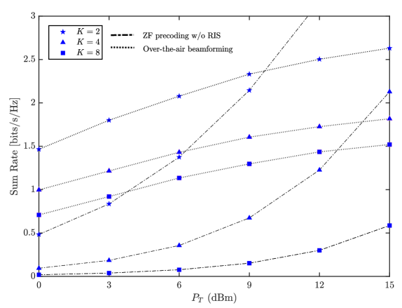
In Figure 3, for a single-user downlink transmission () with and , the achievable rate performance of the proposed over-the-air beamforming scheme as a function of total transmit power is compared to the traditional ZF precoding (Spencer et al., 2004) and the passive RIS-aided joint active and passive beamforming techniques (Wu and Zhang, 2019). Here, while is the overall power consumed at the transmitters of the traditional ZF precoding and joint beamforming transmission schemes, it corresponds to the total power dissipated between the transmitter () and the RIS () for the proposed over-the-air transmission, where and dBm. Moreover, as discussed in Section 2.1, the reference ZF precoding considers a traditional single-hop transmission without RIS that performs transmit precoding before the signal transmission (Spencer et al., 2004). On the other hand, in the joint active and passive beamforming scheme, a passive RIS-aided single-user transmission with the existence of direct links between the transmitter and the user, is considered, where the digital beamforming at the transmitter (active) and analog beamforming at a passive RIS via phase shifters are jointly optimized to enhance the received SNR of the user (Wu and Zhang, 2019). For this purpose, similar to our proposed beamforming technique, a QCQP-based non-convex optimization problem is formulated and an SDR-based solution is performed via CVX solvers (Wu and Zhang, 2019). The results show that although a direct link between the transmitter and the user does not exist in the proposed active RIS-aided over-the-air beamforming scheme, a considerably better performance achievement is observed for compared to the traditional ZF and joint beamforming with passive RIS-aided transmission schemes. Moreover, it is shown that increasing results in enhancement of the achievable rate of all systems. However, in the proposed active RIS-aided over-the-air beamforming scheme, as given in (11), since the magnitude of reflection matrix is restricted with the magnitude of transmission matrix , i.e., increasing , a slighter performance improvement is achieved compared to the benchmark schemes. Furthermore, since a small-scale passive RIS is considered, i.e. , an additional performance improvement due to the indirect RIS-aided link is hardly observed in the passive RIS-aided joint beamforming scheme compared to the conventional ZF precoding scheme.
5.1.2 Multi-user
The following results are carried out for downlink multi-antenna transmission schemes, where a single transmit antenna is allocated to each user, i.e., and .
In Figure 4, the sum rate of the downlink multi-antenna transmission scheme based on the conventional transmit ZF precoding (Spencer et al., 2004) and the novel over-the-air beamforming has been carried out for , and quadrature PSK (QPSK), i.e., . Comparing these two schemes, it is obvious that at lower values, the over-the-air beamforming based multi-user transmission scheme attains higher sum-rate than the classical transmit ZF precoding technique (Spencer et al., 2004). However, for and , as increases, the performance of ZF gradually begins to exceed the performance of the proposed beamforming scheme. Nevertheless, for , the ZF precoder achieves only a slight gain over the proposed beamforming concept at dBm. It can be also deduced from Figure 4 that an increase in the total number of users rapidly decreases ZF sum-rate, however, such a severe performance loss is not observed in the proposed over-the-air beamforming-based system. Moreover, when the number of users further increases to , it is observed that the system with the proposed over-the-air beamforming-based scheme outperforms the system with the traditional ZF technique with a significant performance gain.
In Figure 5, the sum-rate of the proposed over-the-air beamforming-based downlink multi-user system is evaluated for different system configurations. In this case, for a constant , the performance of the over-the-air beamforming based systems are investigated for different number of the reflecting elements , dBm and QPSK signaling. It is observed that increasing RIS size has an adverse affect on the system performance. This results may be explained by the fact that in the over-the-air beamforming design, as given in (11), the power consumed by the reflecting elements is inversely proportional with the magnitude of the channel matrix . Therefore, when a constant is considered for and , it reveals that the proposed beamforming-based systems with the lower values show considerably better performance than the ones with the higher values.
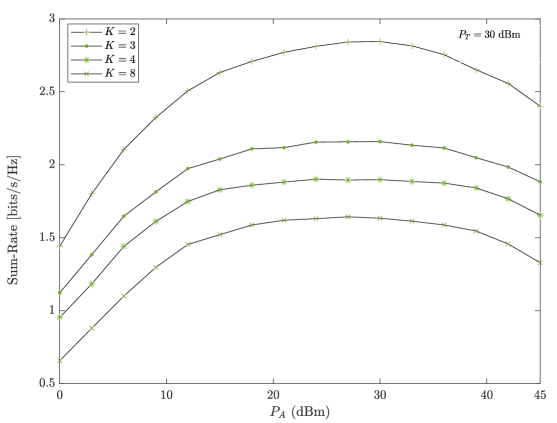
In Figure 6, the effect of increasing reflection power on the sum-rate of the proposed beamforming based systems with QPSK and dBm is investigated for . The results show that in all cases, the increasing improves the system performance up to a certain value, after which the performance begins to degrade. These results indicates the relation between the reflection power constraint and transmitter power in (10). Indeed, in our system design, the overall consumed power is dissipated to the transmitter () and the RIS (), where , and for a constant dBm, decreases with increasing . However, it is clear from (6) that the minimizing directly affects the SINR value. Surely, the investigation of this interesting trade-off points out the importance of the power allocation between the transmitter and the RIS, which is an open problem to be addressed in future studies.
(a)
(b)
5.2 Single-user uplink transmission
In this subsection, the BER performance of the proposed receive IM scheme is evaluated.
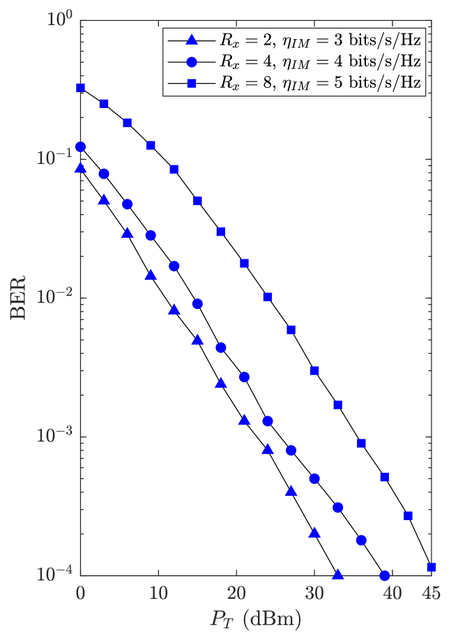
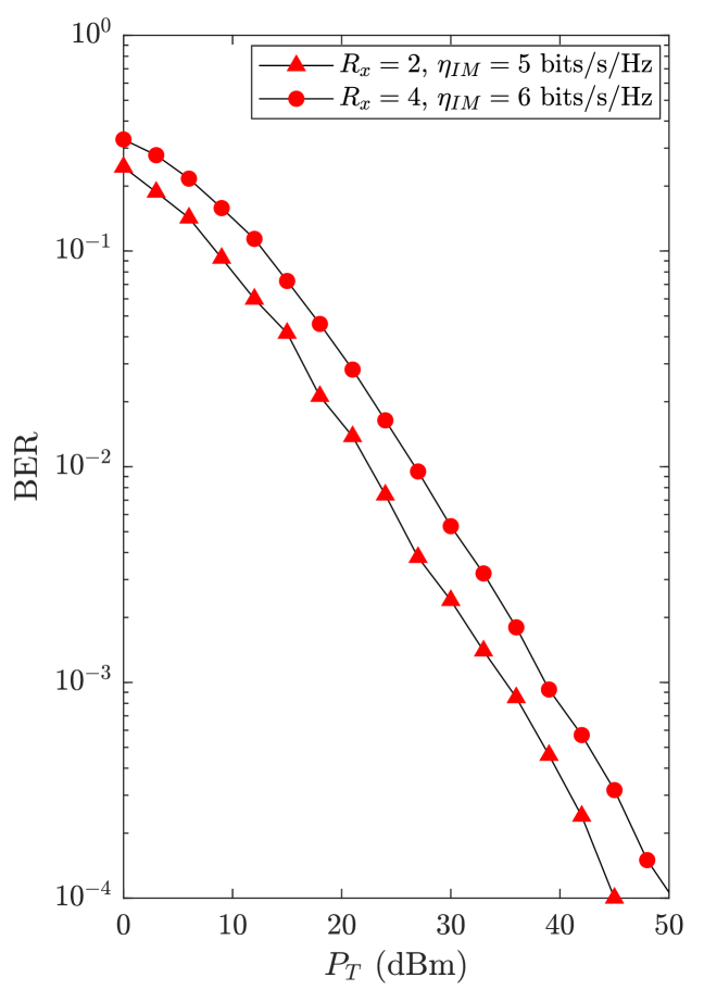
In Figure 7, the BER performance of the proposed receive IM scheme with sub-optimal greedy detector is investigated for different RIS-aided MIMO configurations with and binary PSK (BPSK). Similar to the conventional receive IM schemes (Wu et al., 2021; Zhang et al., 2013), the performance results of the corresponding high-rate systems that employ (a) and (b) transmit antennas reveal a certain trade-off between system performance and data-rate.
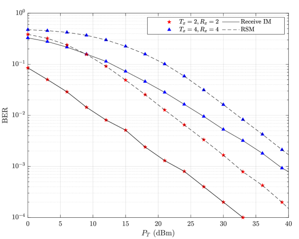
In Figure 8, the BER performance of the transmit ZF precoded receive spatial modulation (RSM) (Zhang et al., 2013) and the proposed over-the-air receive IM schemes are compared. For , the receive IM and the RSM schemes respectively exploit BPSK and QPSK modulations to achieve bits/s/Hz. On the other hand, for configuration, the receive IM with BPSK and the RSM with 16-PSK assess bits/s/Hz. The results demonstrate the significant performance improvement of the proposed receive IM scheme over the traditional ZF precoded RSM (Zhang et al., 2013).
6 Conclusion
In this paper, first, deploying an active RIS, a novel beamforming approach has been proposed for RIS-aided multi-user systems. In the proposed concept, without employing any other signal processing units at the transmitter and/or receiver sides, the reflection coefficients of the active RIS have been customized to mitigate the user interference. To meet this challenge, we have obtained SDR-based solutions via CVX software toolbox. Moreover, taking the proposed over-the-air beamforming concept one step further, a low-complexity receive IM scheme has been developed for single-user uplink transmission. Through computer simulations, the enhanced performance of the over-the-air beamforming-based systems over the traditional precoding-based systems have been indicated.
References
- Almohamad et al. (2020) Almohamad, A., Tahir, A. M., Al-Kababji, A., Furqan, H. M., Khattab, T., Hasna, M. O., et al. (2020). Smart and secure wireless communications via reflecting intelligent surfaces: A short survey. IEEE Open Journal of the Communications Society 1, 1442–1456. 10.1109/OJCOMS.2020.3023731
- Basar (2019) Basar, E. (2019). Transmission through large intelligent surfaces: A new frontier in wireless communications. In 2019 European Conference on Networks and Communications (EuCNC) (IEEE), 112–117
- Basar (2020) Basar, E. (2020). Reconfigurable intelligent surface-based index modulation: A new beyond MIMO paradigm for 6G. IEEE Transactions on Communications 68, 3187–3196. 10.1109/TCOMM.2020.2971486
- Basar et al. (2019) Basar, E., Di Renzo, M., De Rosny, J., Debbah, M., Alouini, M.-S., and Zhang, R. (2019). Wireless communications through reconfigurable intelligent surfaces. IEEE Access 7, 116753–116773
- Basar and Poor (2021) Basar, E. and Poor, H. V. (2021). Present and future of reconfigurable intelligent surface-empowered communications [perspectives]. IEEE Signal Processing Magazine 38, 146–152. 10.1109/MSP.2021.3106230
- Basar et al. (2017) Basar, E., Wen, M., Mesleh, R., Di Renzo, M., Xiao, Y., and Haas, H. (2017). Index modulation techniques for next-generation wireless networks. IEEE Access 5, 16693–16746. 10.1109/ACCESS.2017.2737528
- Basar et al. (2021) Basar, E., Yildirim, I., and Kilinc, F. (2021). Indoor and outdoor physical channel modeling and efficient positioning for reconfigurable intelligent surfaces in mmWave bands. IEEE Transactions on Communications 69, 8600–8611. 10.1109/TCOMM.2021.3113954
- Björnson et al. (2019) Björnson, E., Özdogan, Ö., and Larsson, E. G. (2019). Intelligent reflecting surface versus decode-and-forward: How large surfaces are needed to beat relaying? IEEE Wireless Communications Letters 9, 244–248. 10.1109/LWC.2019.2950624
- Dai et al. (2020) Dai, L., Wang, B., Wang, M., Yang, X., Tan, J., Bi, S., et al. (2020). Reconfigurable intelligent surface-based wireless communications: Antenna design, prototyping, and experimental results. IEEE Access 8, 45913–45923. 10.1109/ACCESS.2020.2977772
- Di et al. (2020) Di, B., Zhang, H., Song, L., Li, Y., Han, Z., and Poor, H. V. (2020). Hybrid beamforming for reconfigurable intelligent surface based multi-user communications: Achievable rates with limited discrete phase shifts. IEEE Journal on Selected Areas in Communications 38, 1809–1822. 10.1109/JSAC.2020.3000813
- Di Renzo et al. (2020) Di Renzo, M., Zappone, A., Debbah, M., Alouini, M.-S., Yuen, C., De Rosny, J., et al. (2020). Smart radio environments empowered by reconfigurable intelligent surfaces: How it works, state of research, and the road ahead. IEEE Journal on Selected Areas in Communications 38, 2450–2525. 10.1109/JSAC.2020.3007211
- Dong and Wang (2020) Dong, L. and Wang, H.-M. (2020). Secure MIMO transmission via intelligent reflecting surface. IEEE Wireless Communications Letters 9, 787–790. 10.1109/LWC.2020.2969664
- El Ayach et al. (2014) El Ayach, O., Rajagopal, S., Abu-Surra, S., Pi, Z., and Heath, R. W. (2014). Spatially sparse precoding in millimeter wave mimo systems. IEEE Transactions on Wireless Communications 13, 1499–1513. 10.1109/TWC.2014.011714.130846
- Ferreira et al. (2020) Ferreira, R. C., Facina, M. S., De Figueiredo, F. A., Fraidenraich, G., and De Lima, E. R. (2020). Bit error probability for large intelligent surfaces under double-Nakagami fading channels. IEEE Open Journal of the Communications Society 1, 750–759. 10.1109/OJCOMS.2020.2996797
- Gao et al. (2022) Gao, Y., Wu, Q., Zhang, G., Chen, W., Ng, D. W. K., and Di Renzo, M. (2022). Beamforming optimization for active intelligent reflecting surface-aided SWIPT. arXiv preprint arXiv:2203.16093
- Gong et al. (2020) Gong, S., Lu, X., Hoang, D. T., Niyato, D., Shu, L., Kim, D. I., et al. (2020). Toward smart wireless communications via intelligent reflecting surfaces: A contemporary survey. IEEE Communications Surveys & Tutorials 22, 2283–2314. 10.1109/COMST.2020.3004197
- Grant and Boyd (2008) Grant, M. and Boyd, S. (2008). Graph implementations for nonsmooth convex programs. In Recent Advances in Learning and Control, eds. V. Blondel, S. Boyd, and H. Kimura (Springer-Verlag Limited), Lecture Notes in Control and Information Sciences. 95–110. http://stanford.edu/~boyd/graph_dcp.html
- Guo et al. (2020) Guo, S., Lv, S., Zhang, H., Ye, J., and Zhang, P. (2020). Reflecting modulation. IEEE Journal on Selected Areas in Communications 38, 2548–2561. 10.1109/JSAC.2020.3007060
- Huang et al. (2019) Huang, C., Zappone, A., Alexandropoulos, G. C., Debbah, M., and Yuen, C. (2019). Reconfigurable intelligent surfaces for energy efficiency in wireless communication. IEEE Transactions on Wireless Communications 18, 4157–4170. 10.1109/TWC.2019.2922609
- Khoshafa et al. (2021) Khoshafa, M. H., Ngatched, T. M., Ahmed, M. H., and Ndjiongue, A. R. (2021). Active reconfigurable intelligent surfaces-aided wireless communication system. IEEE Communications Letters 25, 3699–3703. 10.1109/LCOMM.2021.3110714
- Kilinc et al. (2021) Kilinc, F., Yildirim, I., and Basar, E. (2021). Physical channel modeling for RIS-empowered wireless networks in sub-6 GHz bands. In 2021 55th Asilomar Conference on Signals, Systems, and Computers (IEEE), 704–708
- Kundu and McKay (2021) Kundu, N. K. and McKay, M. R. (2021). Channel estimation for reconfigurable intelligent surface aided MISO communications: From LMMSE to deep learning solutions. IEEE Open Journal of the Communications Society 2, 471–487. 10.1109/OJCOMS.2021.3063171
- Li et al. (2021) Li, Q., Wen, M., and Di Renzo, M. (2021). Single-RF MIMO: From spatial modulation to metasurface-based modulation. IEEE Wireless Communications 28, 88–95. 10.1109/MWC.021.2000376
- Lin et al. (2020) Lin, S., Zheng, B., Alexandropoulos, G. C., Wen, M., Di Renzo, M., and Chen, F. (2020). Reconfigurable intelligent surfaces with reflection pattern modulation: Beamforming design and performance analysis. IEEE Transactions on Wireless Communications 20, 741–754. 10.1109/TWC.2020.3028198
- Long et al. (2021) Long, R., Liang, Y.-C., Pei, Y., and Larsson, E. G. (2021). Active reconfigurable intelligent surface-aided wireless communications. IEEE Transactions on Wireless Communications 20, 4962–4975. 10.1109/TWC.2021.3064024
- Luo et al. (2021) Luo, S., Yang, P., Che, Y., Yang, K., Wu, K., Teh, K. C., et al. (2021). Spatial modulation for RIS-assisted uplink communication: Joint power allocation and passive beamforming design. IEEE Transactions on Communications 69, 7017–7031. 10.1109/TCOMM.2021.3096965
- Luo et al. (2010) Luo, Z.-Q., Ma, W.-K., So, A. M.-C., Ye, Y., and Zhang, S. (2010). Semidefinite relaxation of quadratic optimization problems. IEEE Signal Processing Magazine 27, 20–34. 10.1109/MSP.2010.936019
- Nguyen et al. (2022) Nguyen, N. T., Vu, D., Lee, K., and Juntti, M. (2022). Hybrid relay-reflecting intelligent surface-assisted wireless communications. IEEE Transactions on Vehicular Technology 10.1109/TVT.2022.3158686
- Perović et al. (2021) Perović, N. S., Tran, L.-N., Di Renzo, M., and Flanagan, M. F. (2021). Achievable rate optimization for MIMO systems with reconfigurable intelligent surfaces. IEEE Transactions on Wireless Communications 20, 3865–3882. 10.1109/TWC.2021.3054121
- Shen et al. (2019) Shen, H., Xu, W., Gong, S., He, Z., and Zhao, C. (2019). Secrecy rate maximization for intelligent reflecting surface assisted multi-antenna communications. IEEE Communications Letters 23, 1488–1492. 10.1109/LCOMM.2019.2924214
- Shen et al. (2021) Shen, H., Xu, W., Gong, S., Zhao, C., and Ng, D. W. K. (2021). Beamforming optimization for IRS-aided communications with transceiver hardware impairments. IEEE Transactions on Communications 69, 1214–1227. 10.1109/TCOMM.2020.3033575
- Sohrabi and Yu (2016) Sohrabi, F. and Yu, W. (2016). Hybrid digital and analog beamforming design for large-scale antenna arrays. IEEE Journal of Selected Topics in Signal Processing 10, 501–513. 10.1109/JSTSP.2016.2520912
- Spencer et al. (2004) Spencer, Q. H., Swindlehurst, A. L., and Haardt, M. (2004). Zero-forcing methods for downlink spatial multiplexing in multiuser MIMO channels. IEEE Transactions on Signal Processing 52, 461–471. 10.1109/TSP.2003.821107
- Stavridis et al. (2012) Stavridis, A., Sinanovic, S., Di Renzo, M., and Haas, H. (2012). Transmit precoding for receive spatial modulation using imperfect channel knowledge. In 2012 IEEE 75th Vehicular Technology Conference (VTC Spring) (IEEE), 1–5
- Taha et al. (2021) Taha, A., Alrabeiah, M., and Alkhateeb, A. (2021). Enabling large intelligent surfaces with compressive sensing and deep learning. IEEE Access 9, 44304–44321. 10.1109/ACCESS.2021.3064073
- Tang et al. (2020) Tang, W., Dai, J. Y., Chen, M. Z., Wong, K.-K., Li, X., Zhao, X., et al. (2020). MIMO transmission through reconfigurable intelligent surface: System design, analysis, and implementation. IEEE journal on selected areas in communications 38, 2683–2699. 10.1109/JSAC.2020.3007055
- Thanh Nguyen et al. (2022) Thanh Nguyen, N., Nguyen, V.-D., Wu, Q., Tolli, A., Chatzinotas, S., and Juntti, M. (2022). Hybrid active-passive reconfigurable intelligent surface-assisted multi-user MISO systems. arXiv e-prints , arXiv–2203
- Wu et al. (2021) Wu, M., Lei, X., Zhou, X., Xiao, Y., Tang, X., and Hu, R. Q. (2021). Reconfigurable intelligent surface assisted spatial modulation for symbiotic radio. IEEE Transactions on Vehicular Technology 70, 12918–12931. 10.1109/TVT.2021.3121698
- Wu and Zhang (2019) Wu, Q. and Zhang, R. (2019). Intelligent reflecting surface enhanced wireless network via joint active and passive beamforming. IEEE Transactions on Wireless Communications 18, 5394–5409. 10.1109/TWC.2019.2936025
- Yan et al. (2020) Yan, W., Yuan, X., He, Z.-Q., and Kuai, X. (2020). Passive beamforming and information transfer design for reconfigurable intelligent surfaces aided multiuser mimo systems. IEEE Journal on Selected Areas in Communications 38, 1793–1808. 10.1109/JSAC.2020.3000811
- Ye et al. (2020) Ye, J., Guo, S., and Alouini, M.-S. (2020). Joint reflecting and precoding designs for SER minimization in reconfigurable intelligent surfaces assisted MIMO systems. IEEE Transactions on Wireless Communications 19, 5561–5574. 10.1109/TWC.2020.2994455
- Yigit et al. (2020) Yigit, Z., Basar, E., and Altunbas, I. (2020). Low complexity adaptation for reconfigurable intelligent surface-based MIMO systems. IEEE Communications Letters 24, 2946–2950. 10.1109/LCOMM.2020.3014820
- Yigit et al. (2021a) Yigit, Z., Basar, E., and Altunbas, I. (2021a). SimMBM channel simulator for media-based modulation systems. In 2021 IEEE 32nd Annual International Symposium on Personal, Indoor and Mobile Radio Communications (PIMRC) (IEEE), 531–536
- Yigit et al. (2021b) Yigit, Z., Basar, E., Wen, M., and Altunbas, I. (2021b). Hybrid reflection modulation. arXiv preprint arXiv:2111.08355
- Yu et al. (2019) Yu, X., Xu, D., and Schober, R. (2019). MISO wireless communication systems via intelligent reflecting surfaces. In 2019 IEEE/CIC International Conference on Communications in China (ICCC) (IEEE), 735–740
- Zhang et al. (2020) Zhang, J., Zhang, Y., Zhong, C., and Zhang, Z. (2020). Robust design for intelligent reflecting surfaces assisted MISO systems. IEEE Communications Letters 24, 2353–2357. 10.1109/LCOMM.2020.3002557
- Zhang et al. (2013) Zhang, R., Yang, L.-L., and Hanzo, L. (2013). Generalised pre-coding aided spatial modulation. IEEE Transactions on Wireless Communications 12, 5434–5443. 10.1109/TWC.2013.100213.130848
- Zhang and Zhang (2020) Zhang, S. and Zhang, R. (2020). Capacity characterization for intelligent reflecting surface aided MIMO communication. IEEE Journal on Selected Areas in Communications 38, 1823–1838. 10.1109/JSAC.2020.3000814
- Zhang (2017) Zhang, X. (2017). Matrix analysis and applications (Cambridge University Press)
- Zhang et al. (2021) Zhang, Z., Dai, L., Chen, X., Liu, C., Yang, F., Schober, R., et al. (2021). Active RIS vs. passive RIS: Which will prevail in 6G? arXiv preprint arXiv:2103.15154