Maximizing the Use of Environmental Constraints:
A Pushing-Based Hybrid Position/Force Assembly Skill
for Contact-Rich Tasks
Abstract
The need for contact-rich tasks is rapidly growing in modern manufacturing settings. However, few traditional robotic assembly skills consider environmental constraints during task execution, and most of them use these constraints as termination conditions. In this study, we present a pushing-based hybrid position/force assembly skill that can maximize environmental constraints during task execution. To the best of our knowledge, this is the first work that considers using pushing actions during the execution of the assembly tasks. We have proved that our skill can maximize the utilization of environmental constraints using mobile manipulator system assembly task experiments, and achieve a 100% success rate in the executions.
I INTRODUCTION
In most advanced computer, communication, and consumer electronics (3C) product manufacturing factories, the vast majority of production processes requiring high-precision operations have been efficiently realized by fixed, dedicated automation systems or position-controlled robots [1]. The requirement for the quick setup and reprogram of new robotic assembly lines for new products in 3C factories is rapidly growing [2], [3], [4]. However, dedicated automation systems and position-controlled robots require tedious programming and tuning, thereby prolonging the time to install a new production line. Moreover, they cannot adapt to any unexpected variations in assembly processes [5].
Collaborative robots (cobots) assist in tackling the challenges posed by onerous setup, programming tasks [6],
and unexpected variations in assembly processes through force-control techniques [7]. Mobile manipulator systems were designed to accelerate the long installation and setup times of cobots, as they integrated all the required devices on a “plug-and-play” mobile platform [8], [9]. However, the repeatability of these mobile robots is much worse than that of cobots [10], [3].
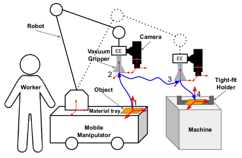
In this paper, we analyze the constraint case when the object and the environment have relative motion, and thus propose a pushing-based hybrid position/force assembly skill accordingly to address the aforementioned challenge. We demonstrated that the proposed skill can maximize the utilization of environmental constraints through a comparative experiment (Figure 1).
II RELATED WORK
II-A Robotic Assembly in 3C Manufacturing Industries
The 3C manufacturing industry is one of the most important industries around the world [11]. A typical manufacturing process can be divided into four main phases: module manufacturing, assembly, testing and packaging, where the latter
three majorly depend dependent on human labor 111https://ri.ust.hk/3C-Industry-Assembly. Robots have been extensively used in structured production environments to ensure consistent yields and efficient manufacturing [12]. However, reinstalling, setting up, and reprogramming robots take several weeks because they cannot rapidly adapt and reorganize with changes in assembly lines.
II-B Mobile Manipulator Programming
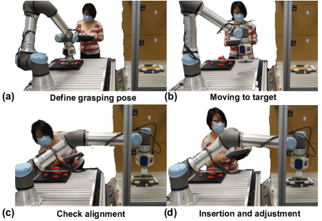
Mobile manipulators were designed to accelerate the setup of robots by integrating the required task devices into a mobile platform. Additionally, several mobile manipulators have been developed and deployed in real manufacturing environments. Traditional robot programming is complex. For example, a typical “pick-and-place” teaching process comprises several steps (Figure 2) [13].
Skill-based task programming methods were designed to enable an easy set up for mobile manipulators [14], [15], in which the predefined functional blocks are adapted to a specific task via several parameters [16]. Although numerous skills have been developed to simplify mobile manipulator programming [14], the research and development of the contact-rich task skills have not been adequately reported.
II-C Operational Space Position/Force Control
Direct/indirect force control techniques have been previously used to overcome the limitation of performing contact-rich manipulation tasks [17], [18]. Additionally, force/motion control is crucial in robotics [19]. A passive compliance element (i.e. remote center compliance) in industrial robots can automate assembly tasks [20], [21]. However, they have to adjust according to the given applications and can only perform well on small deviations in the assembly tasks. To generalize the robotic assembly capabilities, assembly skills based on hybrid position/force trajectories, such as, linear, zigzag, spiral, sinus, and lissajous trajectories, have been developed for robots equipped with force and torque sensors [22].
III PROBLEM STATEMENT
III-A Positioning Accuracy of Mobile Manipulators
In the traditional magnetic tracking approach, the positioning accuracy of mobile manipulators exceed 5 mm, which does not meet the requirements of many industrial applications, such as precision assembly and tending [10], [23]. Visual feedback is an effective method for overcoming position uncertainties during assembly tasks [24], [25]. However, visual feedback includes errors introduced by imaging sensors, lenses, as well as intrinsic and extrinsic parameters [3], steering some researchers to focus more on execution methods than on using accurate vision sensors[3].
III-B Positioning Uncertainty of Flexible End Effector
Vacuum grippers are employed to grasp horizontal or vertical flat objects using suction cups because they can avoid strong contact forces between the object and gripper [26].Therefore, they are frequently used in 3C production factories [27].
Most studies consider assembly tasks as moving already-grasped objects to their goal positions by minimizing the distance between an object and its goal position [28]. However, this assumption has problems owing to contact-rich tasks, particularly when using flexible vacuum grippers [26].
Teach-pendant is frequently employed in factories, particularly in heavily constrained spaces, as shown in Figure 2. However, avoiding strong contact forces is difficult owing to nontransparency issues (Figure 3). Based on our experiments using a vacuum gripper (Model: Bellows Suction Cups SPB1, 1.5 Folds), a contact force of 10 N can produce a translational deformation of up to 1 mm and the respective rotational deformation is even more accentuated.
IV CONSTRAINTS ANALYSIS AND
SKILL DESIGN
IV-A Constraints Analysis
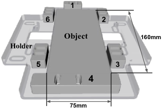
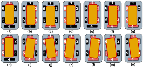
As shown in Figure 4, several adjustable fixtures on the holder are used to fix the object. The fixtures (numbered 1–6) are used to adjust the tension of the holder. According to our analysis, there are several contact states that can cause object and holder misalignments (Figure 5).
According to the contact states analyzed in Figure 5, fixtures may generate a strong contact force between the object and robot, causing a stuck situation. Moreover, owing to the elastic effect of the EE (e.g., vacuum gripper), the concrete contact situation is difficult to distinguish with the force/torque sensor mounted at the wrist of the robot.
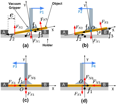
Through the simulations of robot assembly manipulations with human hands, we found that the constraints provided by the fixtures can guide the object alignments with the holder geometry. Figure 6 was used to analyze this phenomenon according to a simplified contact situation, whereas Figure 6(a)–(d) illustrate the pushing action along the direction.
is the initial position error between object and holder. is the translational movement command along the direction. Frame is attached to the center of the object, and is the angle between the object and holder surface. A and B represent the adjustable fixtures on the holder. and represent the maximum static friction and coefficient of static friction between the vacuum gripper and object (the vacuum gripper is released), respectively; and represent the static friction and coefficient of static friction between the object and holder/fixtures, respectively. is the force applied by the vacuum gripper on the object. Additionally, , , , and are the normal forces exerted by the holder/fixtures on the object.
We performed general force analysis on the object along the and directions of frame . In Figure 6(a), the object was assumed to be stationary. The force analysis performed along the direction is represented by the following equation:
| (1) |
represents the force between the vacuum gripper and object in direction:
| (2) |
represents the force between the object and holder along the direction:
| (3) |
Based on Equation 1,
| (4) |
Considering angle , negligible terms were removed from Equation 2 and (4) (when , ), Equation 5 was obtained as follows:
| (5) |
From Equation 5 and Figure 6, we can infer that the coefficient of static friction determines the object’s direction of motion. The same conclusion can be obtained from Figure 6(b). The vacuum grippers are mainly made of rubber 222https://www.festo.com/net/supportportal/files/216340/10783 with a high coefficient of static friction, thus is an easily obtainable condition.
The following results are obtained from Figure 6(c) and (d):
| (6) |
Thus, the entire operation was performed based on the following condition (Figure 6) :
| (7) |
The object can be pushed by the vacuum gripper until it is constrained by the fixtures thereby maximizing the use of environmental constraints. Based on the aforementioned analysis, we designed a pushing-based hybrid position/force assembly skill model to execute the tending task.
IV-B Skill Design
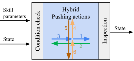
A pushing-based hybrid position/force assembly skill was designed, as shown in Figure 7. Once the state is confirmed, 6 linear hybrid position/force movements are executed according to the skill parameters (i.e., position and force). An inspection was performed after the execution.
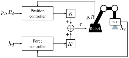
We implemented a hybrid position/force controller under the EE frame for the skill execution (Figure 8), where and are command pose, are current pose; is a command force/torque, and is a feedback force/torque. The diagonal matrices and were used to indicate position or force control under the EE frame. In this study, force control along the direction was defined by Equation 8:
| (8) |
V EXPERIMENTS AND CONCLUSIONS
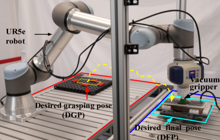
V-A Experiments
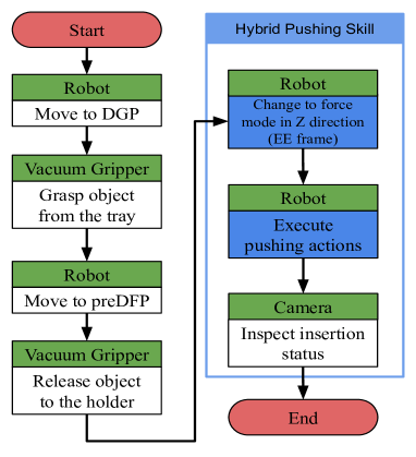
The experiment setup can be found in Figure 9. A UR5e robot was used to implement the machine tending task. The UR5e features a 6-axis and 5–kg payload, a working radius of 850 mm. It is equipped with a 6-DOF force/torque sensor on its EE and uses admittance controller [18] to achieve operational space force control. A workflow was designed to perform the experiment as shown in Figure 10. The skill parameters for the 6 actions (The sequence is shown in Figure 7) are set as:
| (9) |
and denote the amplitudes of the discrete actions. and is set to 8 mm which twice bigger than the error to ensure that the environmental constraints are fully explored. is set to 5 N.
In this experiment, contrary to the perfect group, an error of mm was added along a random direction to the desired final pose to simulate the pose uncertainties in the uncertainty group. We evaluated our proposed method compared with the following baselines:
Baseline 1: spiral search [29]. A spiral search path was used to survey the entire environment surface. Here, the maximum search radius was set to 10mm.
Baseline 2: learning-based search. In this study, a double deep Q-network (DQN) with proportional prioritization [30] was trained as the search policy . This baseline comes from the previous research [13]. The 6-dimensional force-torque vector under the robot EE’s frame was sent to the double DQN, and the force actions along the , and directions were output to the robot controller.
V-B Conclusions
Overall, the results of 600 group robot assembly tasks were recorded, as presented in Table I.
| Baselines | Perfect | Uncertainty |
|---|---|---|
| Baseline 1 | 69/100 | 47/100 |
| Baseline 2 | 95/100 | 91/100 |
| Our method | 100/100 | 100/100 |
Baseline 1 (spiral search) always ended when stopped by one or two fixtures and thus insertion failed, moreover, it always generates sufficiently strong contact force between the objects and the holder. Baseline 2 (learning-based search) offered a high success rate. However, because Baseline 2 uses a neural network to estimate the state, it may sometimes lead to unexpected actions and thus failed. Our method achieves the best success rate in this comparison experiment.
To verify the generalization of our method, we also tested it on two other type holders using our method and obtained a 100% success rate (100/100 trials). Due to space limitation, we do not describe the details in this paper. The test scenes can be seen in the video submitted with the paper.
In future work, the aforementioned results will be combined with other learning-based pushing methods [31] (our previous work) to improve the efficiency and safety of the tending task.
Acknowledgment
We would like to thank Jingjing Sun for her contributions as a robot teaching process volunteer. We also thank mechanical engineer Ningxin Lu for building the hardware mockup system.
References
- [1] S. Ljasenko, N. Lohse, and L. Justham, “Dynamic vs dedicated automation systems-a study in large structure assembly,” Production & Manufacturing Research, vol. 8, no. 1, pp. 35–58, 2020.
- [2] A. Kramberger, B. Nemec, M. Gams, A. Ude et al., “Learning of assembly constraints by demonstration and active exploration,” Industrial Robot: An International Journal, 2016.
- [3] R. Li and H. Qiao, “A survey of methods and strategies for high-precision robotic grasping and assembly tasks—some new trends,” IEEE/ASME Transactions on Mechatronics, vol. 24, no. 6, pp. 2718–2732, 2019.
- [4] C. Sloth, A. Kramberger, and I. Iturrate, “Towards easy setup of robotic assembly tasks,” Advanced Robotics, vol. 34, no. 7-8, pp. 499–513, 2020.
- [5] Z. Zhu and H. Hu, “Robot learning from demonstration in robotic assembly: A survey,” Robotics, vol. 7, no. 2, p. 17, 2018.
- [6] M. Safeea, R. Bearee, and P. Neto, “End-effector precise hand-guiding for collaborative robots,” in Iberian Robotics conference. Springer, 2017, pp. 595–605.
- [7] A. Albu-Schäffer, S. Haddadin, C. Ott, A. Stemmer, T. Wimböck, and G. Hirzinger, “The dlr lightweight robot: design and control concepts for robots in human environments,” Industrial Robot: an international journal, vol. 34, no. 5, pp. 376–385, 2007.
- [8] M. Hvilshøj, S. Bøgh, O. Madsen, and M. Kristiansen, “The mobile robot “little helper”: concepts, ideas and working principles,” in 2009 IEEE Conference on Emerging Technologies & Factory Automation. IEEE, 2009, pp. 1–4.
- [9] C. Wurll, T. Fritz, Y. Hermann, and D. Hollnaicher, “Production logistics with mobile robots,” in ISR 2018; 50th International Symposium on Robotics. VDE, 2018, pp. 1–6.
- [10] S. Su, X. Zeng, S. Song, M. Lin, H. Dai, W. Yang, and C. Hu, “Positioning accuracy improvement of automated guided vehicles based on a novel magnetic tracking approach,” IEEE Intelligent Transportation Systems Magazine, 2018.
- [11] J. Zhang and X. Fang, “Challenges and key technologies in robotic cell layout design and optimization,” Proceedings of the Institution of Mechanical Engineers, Part C: Journal of Mechanical Engineering Science, vol. 231, no. 15, pp. 2912–2924, 2017.
- [12] S. Fang, X. Huang, H. Chen, and N. Xi, “Dual-arm robot assembly system for 3c product based on vision guidance,” in 2016 IEEE International Conference on Robotics and Biomimetics (ROBIO). IEEE, 2016, pp. 807–812.
- [13] Y. Shi, Z. Chen, Y. Wu, D. Henkel, S. Riedel, H. Liu, Q. Feng, and J. Zhang, “Combining learning from demonstration with learning by exploration to facilitate contact-rich tasks,” arXiv preprint arXiv:2103.05904, 2021.
- [14] M. R. Pedersen, L. Nalpantidis, R. S. Andersen, C. Schou, S. Bøgh, V. Krüger, and O. Madsen, “Robot skills for manufacturing: From concept to industrial deployment,” Robotics and Computer-Integrated Manufacturing, vol. 37, pp. 282–291, 2016.
- [15] S. G. Brunner, F. Steinmetz, R. Belder, and A. Dömel, “Rafcon: A graphical tool for engineering complex, robotic tasks,” in 2016 IEEE/RSJ International Conference on Intelligent Robots and Systems (IROS). IEEE, 2016, pp. 3283–3290.
- [16] S. Bøgh, O. S. Nielsen, M. R. Pedersen, V. Krüger, and O. Madsen, “Does your robot have skills?” in Proceedings of the 43rd international symposium on robotics. VDE Verlag GMBH, 2012.
- [17] D. E. Whitney, “Force feedback control of manipulator fine motions,” 1977.
- [18] N. Hogan, “Impedance control: An approach to manipulation: Part i—theory,” 1985.
- [19] A. Stemmer, G. Schreiber, K. Arbter, and A. Albu-Schaffer, “Robust assembly of complex shaped planar parts using vision and force,” in 2006 IEEE International Conference on Multisensor Fusion and Integration for Intelligent Systems. IEEE, 2006, pp. 493–500.
- [20] H. Asada and Y. Kakumoto, “The dynamic rcc hand for high-speed assembly,” in Proceedings. 1988 IEEE International Conference on Robotics and Automation. IEEE, 1988, pp. 120–125.
- [21] W. S. Newman, M. S. Branicky, H. A. Podgurski, S. Chhatpar, L. Huang, J. Swaminathan, and H. Zhang, “Force-responsive robotic assembly of transmission components,” in Proceedings 1999 IEEE International Conference on Robotics and Automation (Cat. No. 99CH36288C), vol. 3. IEEE, 1999, pp. 2096–2102.
- [22] B. Siciliano and O. Khatib, Springer handbook of robotics. springer, 2016.
- [23] G. Schoettler, A. Nair, J. Luo, S. Bahl, J. A. Ojea, E. Solowjow, and S. Levine, “Deep reinforcement learning for industrial insertion tasks with visual inputs and natural rewards,” arXiv preprint arXiv:1906.05841, 2019.
- [24] M. A. Lee, Y. Zhu, K. Srinivasan, P. Shah, S. Savarese, L. Fei-Fei, A. Garg, and J. Bohg, “Making sense of vision and touch: Self-supervised learning of multimodal representations for contact-rich tasks,” in 2019 International Conference on Robotics and Automation (ICRA). IEEE, 2019, pp. 8943–8950.
- [25] Y. Zheng, X. Zhang, Y. Chen, and Y. Huang, “Peg-in-hole assembly based on hybrid vision/force guidance and dual-arm coordination,” in 2017 IEEE International Conference on Robotics and Biomimetics (ROBIO). IEEE, 2017, pp. 418–423.
- [26] A. Jaiswal and B. Kumar, “Vacuum gripper-an important material handling tool,” Int J Sci Technol, vol. 7, pp. 1–8, 2017.
- [27] F. Zhao, H. Gu, C. Li, and C. Chen, “Accuracy analysis for robotized assembly system,” in 2017 IEEE International Conference on Robotics and Biomimetics (ROBIO). IEEE, 2017, pp. 1850–1855.
- [28] J. Luo, E. Solowjow, C. Wen, J. A. Ojea, A. M. Agogino, A. Tamar, and P. Abbeel, “Reinforcement learning on variable impedance controller for high-precision robotic assembly,” in 2019 International Conference on Robotics and Automation (ICRA). IEEE, 2019, pp. 3080–3087.
- [29] I. F. Jasim, P. W. Plapper, and H. Voos, “Position identification in force-guided robotic peg-in-hole assembly tasks,” Procedia Cirp, vol. 23, pp. 217–222, 2014.
- [30] T. Schaul, J. Quan, I. Antonoglou, and D. Silver, “Prioritized experience replay,” arXiv preprint arXiv:1511.05952, 2015.
- [31] L. Cong, M. Grner, P. Ruppel, H. Liang, N. Hendrich, and J. Zhang, “Self-adapting recurrent models for object pushing from learning in simulation,” in 2020 IEEE/RSJ International Conference on Intelligent Robots and Systems (IROS). IEEE, 2020, pp. 5304–5310.