Mechanism of paramagnetic spin Seebeck effect
Abstract
We have theoretically investigated the spin Seebeck effect (SSE) in a normal metal (NM)/paramagnetic insulator (PI) bilayer system. Through a linear response approach, we calculated the thermal spin pumping from PI to NM and backflow spin current from NM to PI, where the spin-flip scattering via the interfacial exchange coupling between conduction-electron spin in NM and localized spin in PI is taken into account. We found a finite spin current appears at the interface under the difference in the effective temperatures between spins in NM and PI, and its intensity increases by increasing the density of the localized spin . Our model well reproduces the magnetic-field-induced reduction of the paramagnetic SSE in Pt/Gd3Ga5O12 experimentally observed when the Zeeman energy is comparable to the thermal energy, which can be interpreted as the suppression of the interfacial spin-flip scattering. The present finding provides an insight into the mechanism of paramagnetic SSEs and the thermally induced spin-current generation in magnetic materials.
I INTRODUCTION
Spin Seebeck effect (SSE) Uchida et al. (2008, 2014a, 2016); Uchida (2021); Kikkawa and Saitoh (2022) refers to the spin-current generation from a temperature gradient applied to a magnet. The generated spin current flows along the temperature gradient and can be detected as a voltage signal in an attached normal metal (NM) electrode, such as Pt, using the inverse spin Hall effects (ISHEs) Azevedo et al. (2005); Saitoh et al. (2006); Kimura et al. (2007); Valenzuela and Tinkham (2006); Sinova et al. (2015). Up to now, the SSEs have been investigated in various magnetically ordered materials, including ferrimagnets Uchida et al. (2010, 2014b); Geprägs et al. (2016); Oh et al. (2021), ferromagnets Ito et al. (2019); Mallick et al. (2019), and antiferromagnets Seki et al. (2015); Wu et al. (2016); Rezende et al. (2016); Li et al. (2020); Reitz et al. (2020); Kikkawa et al. (2021). In the mechanism of the SSEs in the ordered magnets, magnon excitation plays an important role. Xiao formulated the thermal spin pumping theory for the SSEs in a NM/ferromagnetic insulator (FM) bilayer Xiao et al. (2010). In this mechanism, the temperature difference between the effective magnon temperature in FM and electron temperature in NM generated by the applied temperature gradient creates an imbalance between thermal spin pumping from FM to NM and the backflow spin current from NM to FM, resulting in a finite spin current across the interface Bender et al. (2012); Adachi et al. (2013). Subsequently, Rezende proposed another mechanism of the SSEs originating from the bulk magnon transport induced by the temperature gradient based on diffusion equations of magnons Rezende et al. (2014); Rezende (2020).
The SSEs are also found in paramagnetic materials, where the conventional magnon excitation/transport can not be responsible for the mechanism of the SSEs. Wu reported that the SSEs in paramagnetic insulators (PIs) Gd3Ga5O12 and DyScO3 at low temperatures close to their Curie-Weiss temperatures Wu et al. (2015a). By measuring the SSEs across the phase transition temperatures, the paramagnetic SSEs have been found in the paramagnetic phase of CoCr2O4 Aqeel et al. (2015), FeF2 Li et al. (2019), SrFeO3 Hong et al. (2019), and CrSiTe3 and CrGeTe3 Ito et al. (2019). The SSEs from paramagnets were also found in the one-dimensional (1D) quantum spin liquid (QSL) system Sr2CuO3 Hirobe et al. (2017, 2018) and spin dimer systems CuGeO3 Chen et al. (2021), Pb2V3O9 Xing et al. (2022), and VO2 Luo et al. (2022). The SSEs in quantum spin systems are attributed to the thermal generation of exotic spin excitations in the systems, i.e., spinons in the 1D QSL and triplons in the spin dimer system, respectively. However, the mechanism of the thermally induced spin-current generation in a junction of NM and classical PI is not established; only a few theoretical studies addressed the spin currents in NM/PI junctions Okamoto (2016); Yamamoto et al. (2019); Zhang et al. (2019); Nakata and Ohnuma (2021).
In this paper, we developed a theoretical model of the SSE in a bilayer of a NM and classical PI by considering the spin-flip scattering due to the interfacial exchange interaction between conduction-electron spins in NM and localized spins in PI. We calculated thermal spin pumping from PI to NM and back-flow spin current from NM to PI at the NM/PI interface based on a linear response formalism Kajiwara et al. (2010); Takahashi et al. (2010). The system is characterized by the effective temperatures of the localized spins in PI, , and conduction electron spins in NM, . The finite spin current arises when due to the imbalance between the thermal spin pumping and back-flow spin current, and its intensity is proportional to the density of the spin of the paramagnetic localized ion in PI. We describe as a function of a single parameter , where and represent the magnetic field and temperature , respectively. To compare the theoretical results with the experiments, we conducted the SSE measurements in a Pt/Gd3Ga5O12(GGG) junction, where GGG is known as a classical paramagnet down to low temperatures. Our model well explains the experimental dependence of the paramagnetic SSE in Pt/GGG, which clarifies that the dependence of the paramagnetic SSE is attributed to the competition between the -induced spin alignment (increasing ) and the Zeeman gap opening (decreasing ) with increasing . A difference in the experimental and theoretical dependences was found, which may be attributed to the effect of the thermal conductivity in GGG and interfacial Kapitza conductance.
II SPIN CURRENT AT NM/PI
In this section, we formulate the interfacial spin current in a NM/PI junction by taking the interfacial spin-flip scattering into account and apply the result to the case of the SSE. Conduction electrons in NM and localized spins in PI are coupled by the interfacial exchange interaction, leading to the exchange of the spin angular momentum and energy via the spin-flip scattering. Our formulation shows that the interfacial spin current is proportional to a Brillouin function of spins in PI, the density of the spin of magnetic ions in PI, and the difference between the distribution function of the PI and NM sides.
II.1 Model
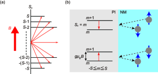
We model the spin and energy transfer by the spin-flip scattering across a NM/PI interface biased by an external driving force such as a temperature gradient. Figure 1(a) shows the energy levels of paramagnetic spin under the magnetic field . At zero field, all spins are degenerated in a single energy level. By applying , the spin degeneracy is lifted to split into different energy levels (). Each energy level is separated with the Zeeman energy of , where is the -factor and is the Bohr magneton. We show a schematic illustration of the spin-flip scattering in Fig. 1(b). The spin-flip scattering causes the exchange of spin angular momentum of and energy of between a conduction electron in NM and a localized spin in PI, where is the Dirac’s constant. When an up-spin (down-spin) electron in NM interacts with a localized spin in PI, the spin-flip scattering lowers (raises) the energy state of the spin at the interface, generating a nonequilibrium spin state in PI [see the upper (lower) part of Fig. 1(b)]. We assume the local thermal equilibrium, which indicates that a state of the spin system X (X = NM or PI) is characterized by the effective temperature of and spin chemical potential . Here, the spin chemical potential in PI, , is similar to the magnon chemical potential in magnetic insulators Cornelissen et al. (2016), but the physical picture is quite different because PI has no (well-defined) magnon. The magnon chemical potential represents the number of the nonequilibrium magnons, while corresponds to the amount of the nonequilibrium spins, i.e., the number of flipped spins different from the thermal equilibrium as a result of the spin-flip scattering at the interface.
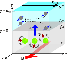
Figure 2 shows the considered NM/PI junction with the static magnetic field in the direction. In the case of the SSE, when we apply the temperature difference between NM and PI in the direction (), the net spin and energy exchange appears via the spin-flip scattering between the conduction electron spin and localized spin at the interface resulting in the generation of a spin current in the direction. The injected is converted into an electric field via ISHE in NM and can be measured as a voltage signal in the direction.
II.2 Thermal average of spin
First of all, we show the field-induced magnetization in PI, corresponding to the thermal average of the magnetization component parallel to . The partition function of paramagnetic spins , where is the Boltzmann constant and is the temperature, gives and the spin-spin correlation function as
| (1) | ||||
| (2) |
where is the Brillouin function of spin as a function of , is the dimensionless ratio of the Zeeman energy to the thermal energy, and . As the Brillouin function is parameterized by consisting of two independent parameters and , an increase (decrease) of corresponds to the increased (decreased) at the fixed or the decreased (increased) at the fixed in actual experiment.
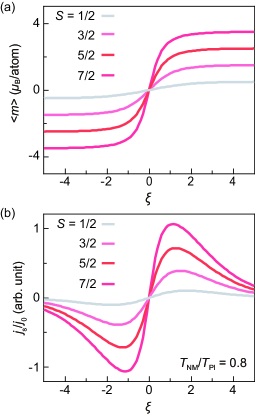
Figure 3(a) shows the calculation of Eq. (1) with different values. In a small regime (small or high condition), linearly increases, showing a typical Curie-Weiss behavior. Above , is saturated to the value of because all spins align along the direction of .
We simply considered the non-interacting paramagnetic spins, i.e., the exchange interaction among the paramagnetic spins is zero. This assumption is a good approximation when the system is under high or small . However, finite exchange interaction in realistic materials becomes important when the system is under low or large , where the energy scale of the system is comparable to that of the exchange interaction, characterized by the Curie-Weiss temperature. In comparison with experimental results (Sec. III), we take the actual exchange interaction into account using the lowest-order approximation of a molecular field theory because the paramagnetic SSE was observed at low and large . We replaced with the Curie-Weiss molecular (effective) magnetic field Hu et al. (2014); Daudin et al. (1982) , where is the Curie-Weiss temperature of the considered paramagnet to calculate Eqs. (1) and (2), when we apply our model to a specific case such as the Pt/GGG interface in Sec. III. In the case of ferromagnetic exchange interaction (), our approximation is only valid in , because diverges at . By contrast, in the case of antiferromagnetic exchange interaction, is negative, and is always well defined and gives quantitative calculation for .
II.3 Spin current at NM/PI interface
We formulate the spin-current density at the interface with the interfacial exchange interaction between the conduction electron in NM and localized spin in PI based on the linear response theory for the spin current in the NM/FM junction Takahashi et al. (2010). The interfacial exchange interaction Hamiltonian reads
| (3) |
where is the coefficient of the interfacial exchange interaction, is the local spin at the position and time , is the conduction electron spin density at , is the unit cell volume of NM, and is the number of local spins at the interface.
The spin-current density operator polarized in the direction and flowing in the direction at the interface , where is the number operator of the conduction electron with spin () and is the area size of the interface, is calculated by the Heisenberg equation of motion as
| (4) |
We calculate the second-order perturbation of NM by the interfacial exchange interaction using the linear response theory and obtain the spin current density across the interface as
| (5) |
where spin is a representative of at the interface, is the interfacial spin density, and is the ladder operator for the local spin with the quantized axis chosen along , and are the transverse spin density of the conduction electrons in NM, and and are the creation and annihilation operator of an electron with momentum and spin , respectively, and is the one-electron energy.
The spin-spin correlation function of the localized spin in PI can be written as
| (6) |
| (7) |
where is a quantum number of , which we call the magnetization along of the paramagnetic spins in PI. We take into account for calculating and using Eqs. (1) and (2) to consider the spin-current-induced nonequilibrium spin states in PI. By putting Eqs. (6) and (7) into Eq. (II.3), becomes
| (8) |
where and . The spin-spin correlation function of the conduction-electron part can be calculated as
| (9) | ||||
| (10) |
where is the density of state at the Fermi level and is the Lamor frequency, and is the Bose distribution function with energy and temperature . Finally, we obtain
| (11) |
where and is the dimensionless interfacial exchange interaction. We found that is proportional to the thermal average of the magnetization of PI () and the difference between the distribution function of PI and NM. Because the spin state is labelled by the effective temperature and spin chemical potential (X = NM or PI), Eq. (II.3) indicates the finite spin current appears when and/or between NM and PI are different. The difference of and between NM and PI arises, for example, when the temperature gradient is applied to the system and SHE creates spin accumulation in the NM side by the application of the current. It is worth mentioning that Eq. (II.3) gives the general form of the interfacial spin current at NM/PI, which can be applied to the SSEs as well as the nonlocal spin transport Oyanagi et al. (2019) and spin Hall magnetoresistance Zhang et al. (2019); Oyanagi et al. (2021) with paramagnetic insulators.
II.4 Application to SSE in NM/PI system
In this subsection, we apply Eq. (II.3) to describe the SSE in the NM/PI system by calculating the interfacial spin current in Eq. (II.3) under a temperature difference between PI and NM (). By application of a small temperature difference , an imbalance of the thermal spin pumping from PI and the back-flow spin current from NM appears, resulting in a finite flow of spin current at the interface. In NM, the resultant spin current creates the spin accumulation, which diffuses and is converted into a voltage via the ISHE.
Figure 3(b) shows the calculation of as a function of at various for . To focus on the effect of the temperature difference, we set in the calculation. The calculated spin current changes the sign by reversing the sign of . The magnitude of increases for and takes a maximum value at , while it decreases for . disappears at . With the increase in , the maximum value of monotonically increases. The dependence of in is consistent with that of [see Eq. (II.3) and Fig. 3(a)], indicating the aligning of the localized spins in PI by the -induced increase in . The decrease of is substantial when the Zeeman energy exceeds thermal energy () because of the suppression of the spin-flip scattering at the interface [see Fig. 1(b)]. Our result indicates that the finite magnetization is responsible for the generation of the interfacial spin current, and the overall shape of is related to the -induced alignment of localized spin and Zeeman gap opening.
We next describe the effect of a finite spin accumulation on the SSE. The thermally generated spin current flows across the interface and creates in NM, which diffuses to flow in NM, . Due to the ISHE in NM, generates an electric field [see Fig. 2] given by , where is the spin Hall angle of NM, is the resistivity of NM, is the elementary charge, and is the average of over . By solving the spin diffusion equation for in NM with the spin-current continuity boundary condition, the ISHE-induced voltage, , becomes
| (12) |
where is the spin diffusion length of NM, is the length of the NM contact, and is the thickness of NM. Expanding in Eq. (II.3) up to the linear order in both and , and using the solution for the spin diffusion equation, we obtain the interfacial spin current as
| (13) |
where is the spin Seebeck conefficient
| (14) |
with the effective spin conductance Oyanagi et al. (2019); Zhang et al. (2019); Oyanagi et al. (2021),
| (15) |
for small temperature difference () and small spin conductance condition (), which is always satisfied at sufficiently low temperatures.
III EXPERIMENTAL RESULTS AND COMPARISON WITH THEORY
In this section, we show that our model well explains the observed paramagnetic SSE signal in the Pt/GGG sample [Figs. 4(a) and 4(b)]. We observed the paramagnetic SSE in the low temperatures ( K) and high magnetic field ( T) regime similar to the previous reports Wu et al. (2015a); Liu et al. (2018).
III.1 Magnetization of GGG
Paramagnetic insulator GGG is commonly used as a substrate for growing a thin-film ferrimagnetic Y3Fe5O12 (YIG) Sun et al. (2012) in spintronics and magnonics Serga et al. (2010); Chumak et al. (2015). Since the Ga3+ ion is nonmagnetic, the magnetic property of GGG is governed by the Gd3+ ions with the small antiferromagnetic exchange interaction of K Schiffer et al. (1995). GGG shows no long-range magnetic ordering down to 180 mK and has a small Curie-Weiss temperature of K Schiffer et al. (1995), making GGG an ideal classical paramagnetic system.
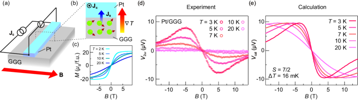
Figure 4(c) shows the dependence of GGG’s magnetization, , measured by a vibrating sample magnetometer at various . The saturation magnetization of 21 is consistent with the expected value for Gd3Ga5O12, where Gd3+ () carries 7. The curve at the lowest of 3 K shows a Brillouin-function-like response; is saturated at large . 3(a). By contrast, at 20 K increases linearly with and resembles the calculated for . at low (high) corresponds to the curves in the large (small) region in Fig. 3(a). All magnetization measurement results indicate GGG obeys the Curie-Weiss law down to low temperature.
III.2 Experimental setup and results
We fabricated an on-chip spin Seebeck device Wu et al. (2015b, a, 2016); Kikkawa et al. (2021) schematically shown in Fig. 4(a). The device consists of a Pt strip on a GGG slab ( mm3) commercially obtained from CRYSTAL GmbH. Before the nanofabrication, we cleaned the GGG slab in acetone for 5 minutes using an ultrasonication bath. We picked up it from acetone and blew off the acetone residue on top of the GGG slab with dried nitrogen gas. We used positive resist PMMA 950A and conductive organic polymer ESPACER (Showa Denko) for preventing charge up during the -beam lithography. The dimension of Pt is 200 m long, 100 nm wide, and 10 nm thickness prepared by magnetron sputtering, -beam lithography and lift-off methods Cornelissen et al. (2017); Oyanagi et al. (2019, 2020). We confirmed that the surfaces of the GGG substrate and Pt film have small surface roughnesses using an atomic force microscope [please see Figs. 6(a) and (b) in Appendix A]. The Pt strip works as a heater as well as a spin-current detector. We generate Joule heating to induce a thermal gradient across the Pt/GGG interface by applying a current with magnitude . The generated drives a spin current at the interface via the exchange interaction between localized spins in GGG and conduction electron spins in Pt [see Fig. 4(b)]. The spin current is converted into a voltage signal via the ISHE in Pt. We applied with the frequency of 13.423 Hz and root-mean-square amplitude of 10 A, which corresponds to the heating power of W. We fixed the heating power instead of the temperature difference in the SSE measurements, which is different from the theoretical calculation with the input of the constant temperature difference. We confirmed that the system temperature remains unchanged during the SSE measurements, indicating the temperature increase due to Joule heating is negligible. As the thermally induced spin current has the same frequency of the Joule heating (), we measured the second harmonic voltage across the Pt strip using a lock-in method to resolve the resultant SSE signals.
Figure 4(d) shows the dependence of in the Pt/GGG sample for various . At K, we observed no voltage signal. With decreasing , a clear appears, whose sign changes with respect to the direction. This is due to the reversal of the direction of the localized spins in GGG and the spin-current polarization. The maximum signal intensity rapidly increases with decreasing . below 10 K linearly increases up to T and takes the maximum value at around T. By further increasing , starts to decrease, showing the -induced reduction of the paramagnetic SSE. All observation here is consistent with the results of the paramagnetic SSE reported by Wu Wu et al. (2015a).
III.3 Calculation of spin Seebeck voltage in Pt/GGG
We numerically calculated the paramagnetic spin Seebeck voltage in the Pt/GGG system given by Eq. (12) with the material parameters summarized in Table I using Microsoft Excel. Figure 4(e) shows under the constant temperature difference of mK at the selected . At all , appears with the application of and changes the sign under the reversal. At 10 K, increases with T and shows a broad peak at around 5 T. In the T range, we found the -induced reduction of . By contrast, at 10 K monotonically increases up to T. Note that the dependence at low (high) corresponds to the dependence of for () [see Fig. 3(b)].
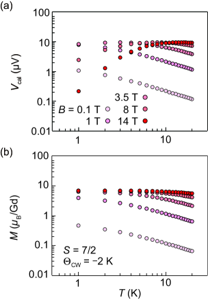
Next, we investigated the dependence of . Figure 5(a) shows at various values. Except for at T, monotonically increases in K K. This behavior is similar to , where follows the Curie-Weiss law [] shown in Fig. 5(b). Below 5 K, at T increases down to 1 K, while at T decreases, corresponding to the -induced reduction of . This is different from the saturation behavior of in the low and high range.
III.4 Comparison between theory and experiment
By comparing Figs. 4(d) and 4(e), we found that the calculation well reproduces the experimental dependence of the paramagnetic SSE. The agreement between the calculation and experiments indicates that the -induced reduction of the paramagnetic SSE is ascribed to the competition between the Zeeman energy () and thermal energy (). When sufficiently large , such as , is applied, the spin-flip scattering reduces because the thermal energy cannot overcome the Zeeman gap [see Fig. 1(b)], and thus the interfacial spin current and SSE signal reduce. The same mechanism is also responsible for the -induced reduction of the SSE in FMs at low , where freeze-out of magnons prohibits the thermal magnon excitation Kikkawa et al. (2015); Jin et al. (2015); Kikkawa et al. (2016); Oyanagi et al. (2020).
| Symbol | Value | Unit | |||
|---|---|---|---|---|---|
| Platinum spin diffusion length | 2 | nm | |||
| Platinum spin Hall angle | 0.11 | - | |||
| Platinum resistivity | 3.4 | m | |||
| Gd spin angular momentum | 7/2 | - | |||
|
-1.27 | K | |||
|
-0.065 | - | |||
| Interfacial Gd atom density | 6.94 | Gd/m2 |
We found that and show good agreement in the amplitude at 3 K with the input of mK and the material parameters in Table I. This value is comparable to the increase of the Pt surface temperature estimated in the similar Pt/GGG device at 2 K using the thermal simulation Liu et al. (2018). The interfacial temperature difference originates from an effective Kapitza conductance , which relates the injected heat flux to at the interface Reitz et al. (2020). We obtained Wm-2K-1 at 3 K, which reasonably agrees to that in Pt/YIG at low temperatures of 40 K Angeles et al. (2021). However, it may also indicate the possible overestimation of because of the strong decrease of at lower temperatures Kent (1993). For more quantitative comparison, we need detailed experiments on the interfacial heat and spin transport at low temperatures.
Finally, we discuss the dependence of the paramagnetic SSE. The interface spin current takes the maximum at shown in Fig. 3(b), and so does at . Quantitatively, at T shows the dependence in K K, above K. However, the experimental results reported by Wu Wu et al. (2015a) show the faster power-law decay of the signal, , in the Pt/GGG system in the condition. We also obtained a similar dependence in our experimental results. The difference can be caused by the dependence of . In our calculation, we fixed the constant value of 16 mK for obtaining , corresponding to the intrinsic dependence of the paramagnetic SSE. However, in the experiments, actual is not constant with varying , even though the heating power is fixed. At low , the thermal conductivity of GGG strongly decreases with decreasing Daudin et al. (1982), causing the dependence of , which affects the dependence of the paramagnetic SSE voltage signal. Indeed, Wu obtained the dependence of the paramagnetic SSE voltage signal by taking the dependence of the thermal conductivity of GGG, the Kapitza conductance at the interface, and of GGG into account. Comparison with our calculation and experimental results measured with constant Iguchi et al. (2017) may provide further insight into the dependence of paramagnetic SSE in this system.
IV SUMMARY
We theoretically investigated the spin Seebeck effect (SSE) in a normal metal (NM)/paramagnetic insulator (PI) junction. The spin and energy exchange appears at the NM/PI interfacial due to the spin-flip scattering between the conduction electron spins in NM and localized spins in PI. We calculated the spin current density at the interface using the linear response theory and found that the finite spin current appears when the temperatures of spins in NM and PI are different. The interfacial spin-current density is governed by values of the electron spin of the localized spin in PI and . When , the spin current density increases due to the alignment of the localized spin, while the spin current density is rapidly suppressed when because the Zeeman energy exceeds thermal energy, resulting in the suppression of the spin-flip scattering. The good agreement between the calculated and measured dependences of the paramagnetic SSE voltage in the Pt/GGG system at low temperatures indicates that the -induced reduction of the paramagnetic SSE is attributed to the suppression of the interfacial spin-flip scattering due to the Zeeman gap opening. Recent studies on the long-rage spin transport in paramagnets Oyanagi et al. (2019); Luo et al. (2022) indicate the importance of bulk spin transport, and thus future work on a SSE theory based on bulk spin and heat transport in paramagnets is important to clarify the role of spin-wave excitation mediated by the dipole interaction for the paramagnetic SSE. Our results clarify the mechanism of the thermally induced spin transport at NM/PI interfaces and give insight into the thermal spin current generation in spin caloritronics Bauer et al. (2012).
ACKNOWLEDGMENT
We thank S. Daimon, G. E. W. Bauer and B. J. van Wees for fruitful discussion. This work is a part of the research program of ERATO “Spin Quantum Rectification Project” (No. JPMJER1402) and CREST (Nos. JPMJCR20C1 and JPMJCR20T2) from JST, the Grant-in-Aid for Scientific Research on Innovative Area “Nano Spin Conversion Science” (No. JP26103005), the Grant-in-Aid for Scientific Research (S) (No. JP19H05600), Grant-in-Aid for Scientific Research (B) (No. JP20H02599), Grant-in-Aid for Research Activity start-up (No. JP20K22476), Grant-in-Aid for Early-Career Scientists (No. 21K14519) from JSPS KAKENHI, JSPS Core-to-Core program, the International Research Center for New-Concept Spintronics Devices, World Premier International Research Center Initiative (WPI) from MEXT, Japan, and Institute for AI and Beyond of the University of Tokyo. K.O. acknowledges support from GP-Spin at Tohoku University.
Appendix A: Surface of GGG and Pt film on GGG
Figures 6(a) and 6(b) show the atomic force microscope (AFM) images of the surface of the GGG substrate after the cleaning and Pt film on GGG. We found similar values of the surface roughness: = 0.3 nm for the GGG substrate and = 0.4 nm for the Pt film. of 0.4 nm is much smaller than the Pt thickness, indicating high quality and uniformity of the film.

References
- Uchida et al. (2008) K. Uchida, S. Takahashi, K. Harii, J. Ieda, W. Koshibae, K. Ando, S. Maekawa, and E. Saitoh, Nature (London) 455, 778 (2008).
- Uchida et al. (2014a) K. Uchida, M. Ishida, T. Kikkawa, A. Kirihara, T. Murakami, and E. Saitoh, J. Phys. Condens. Matter 26, 343202 (2014a).
- Uchida et al. (2016) K.-i. Uchida, H. Adachi, T. Kikkawa, A. Kirihara, M. Ishida, S. Yorozu, S. Maekawa, and E. Saitoh, Proc. IEEE 104, 1946 (2016).
- Uchida (2021) K.-I. Uchida, Proc. Jpn. Acad., Ser. B 97, 69 (2021).
- Kikkawa and Saitoh (2022) T. Kikkawa and E. Saitoh, arXiv preprint arXiv:2205.10509 (2022).
- Azevedo et al. (2005) A. Azevedo, L. H. Vilela Leão, R. L. Rodriguez-Suarez, A. B. Oliveira, and S. M. Rezende, J. Appl. Phys. 97, 10C715 (2005).
- Saitoh et al. (2006) E. Saitoh, M. Ueda, H. Miyajima, and G. Tatara, Appl. Phys. Lett. 88, 182509 (2006).
- Kimura et al. (2007) T. Kimura, Y. Otani, T. Sato, S. Takahashi, and S. Maekawa, Phys. Rev. Lett. 98, 156601 (2007).
- Valenzuela and Tinkham (2006) S. O. Valenzuela and M. Tinkham, Nature (London) 442, 176 (2006).
- Sinova et al. (2015) J. Sinova, S. O. Valenzuela, J. Wunderlich, C. Back, and T. Jungwirth, Rev. Mod. Phys. 87, 1213 (2015).
- Uchida et al. (2010) K. Uchida, J. Xiao, H. Adachi, J.-i. Ohe, S. Takahashi, J. Ieda, T. Ota, Y. Kajiwara, H. Umezawa, H. Kawai, et al., Nat. Mater. 9, 894 (2010).
- Uchida et al. (2014b) K. Uchida, M. Ishida, T. Kikkawa, A. Kirihara, T. Murakami, and E. Saitoh, J. Phys. Condens. Matter 26, 343202 (2014b).
- Geprägs et al. (2016) S. Geprägs, A. Kehlberger, F. Della Coletta, Z. Qiu, E.-J. Guo, T. Schulz, C. Mix, S. Meyer, A. Kamra, M. Althammer, et al., Nat. Commun. 7, 10452 (2016).
- Oh et al. (2021) I. Oh, J. Park, D. Choe, J. Jo, H. Jeong, M.-J. Jin, Y. Jo, J. Suh, B.-C. Min, and J.-W. Yoo, Nat. Commun. 12, 1057 (2021).
- Ito et al. (2019) N. Ito, T. Kikkawa, J. Barker, D. Hirobe, Y. Shiomi, and E. Saitoh, Phys. Rev. B 100, 060402 (2019).
- Mallick et al. (2019) K. Mallick, A. A. Wagh, A. Ionescu, C. H. Barnes, and P. A. Kumar, Phys. Rev. B 100, 224403 (2019).
- Seki et al. (2015) S. Seki, T. Ideue, M. Kubota, Y. Kozuka, R. Takagi, M. Nakamura, Y. Kaneko, M. Kawasaki, and Y. Tokura, Phys. Rev. Lett. 115, 266601 (2015).
- Wu et al. (2016) S. M. Wu, W. Zhang, K. C. Amit, P. Borisov, J. E. Pearson, J. S. Jiang, D. Lederman, A. Hoffmann, and A. Bhattacharya, Phys. Rev. Lett. 116, 097204 (2016).
- Rezende et al. (2016) S. Rezende, R. Rodríguez-Suárez, and A. Azevedo, Phys. Rev. B 93, 014425 (2016).
- Li et al. (2020) J. Li, C. B. Wilson, R. Cheng, M. Lohmann, M. Kavand, W. Yuan, M. Aldosary, N. Agladze, P. Wei, M. S. Sherwin, et al., Nature (London) 578, 70 (2020).
- Reitz et al. (2020) D. Reitz, J. Li, W. Yuan, J. Shi, and Y. Tserkovnyak, Phys. Rev. B 102, 020408 (2020).
- Kikkawa et al. (2021) T. Kikkawa, D. Reitz, H. Ito, T. Makiuchi, T. Sugimoto, K. Tsunekawa, S. Daimon, K. Oyanagi, R. Ramos, S. Takahashi, et al., Nat. Commun. 12, 4356 (2021).
- Xiao et al. (2010) J. Xiao, G. E. Bauer, K.-c. Uchida, E. Saitoh, S. Maekawa, et al., Phys. Rev. B 81, 214418 (2010).
- Bender et al. (2012) S. A. Bender, R. A. Duine, and Y. Tserkovnyak, Phys. Rev. Lett. 108, 246601 (2012).
- Adachi et al. (2013) H. Adachi, K.-i. Uchida, E. Saitoh, and S. Maekawa, Rep. Prog. Phys. 76, 036501 (2013).
- Rezende et al. (2014) S. M. Rezende, R. L. Rodríguez-Suárez, R. Cunha, A. R. Rodrigues, F. L. A. Machado, G. A. F. Guerra, J. C. L. Ortiz, and A. Azevedo, Phys. Rev. B 89, 014416 (2014).
- Rezende (2020) S. M. Rezende, Fundamentals of magnonics, vol. 969 (Springer, 2020).
- Wu et al. (2015a) S. M. Wu, J. E. Pearson, and A. Bhattacharya, Phys. Rev. Lett. 114, 186602 (2015a).
- Aqeel et al. (2015) A. Aqeel, N. Vlietstra, J. A. Heuver, G. E. W. Bauer, B. Noheda, B. J. van Wees, and T. T. M. Palstra, Phys. Rev. B 92, 224410 (2015).
- Li et al. (2019) J. Li, Z. Shi, V. H. Ortiz, M. Aldosary, C. Chen, V. Aji, P. Wei, and J. Shi, Phys. Rev. Lett. 122, 217204 (2019).
- Hong et al. (2019) D. Hong, C. Liu, J. E. Pearson, A. Hoffmann, D. D. Fong, and A. Bhattacharya, Appl. Phys. Lett. 114, 242403 (2019).
- Hirobe et al. (2017) D. Hirobe, M. Sato, T. Kawamata, Y. Shiomi, K.-i. Uchida, R. Iguchi, Y. Koike, S. Maekawa, and E. Saitoh, Nat. Phys. 13, 30 (2017).
- Hirobe et al. (2018) D. Hirobe, T. Kawamata, K. Oyanagi, Y. Koike, and E. Saitoh, J. Appl. Phys. 123, 123903 (2018).
- Chen et al. (2021) Y. Chen, M. Sato, Y. Tang, Y. Shiomi, K. Oyanagi, T. Masuda, Y. Nambu, M. Fujita, and E. Saitoh, Nat. Commun. 12, 5199 (2021).
- Xing et al. (2022) W. Xing, R. Cai, K. Moriyama, K. Nara, Y. Yao, W. Qiao, K. Yoshimura, and W. Han, Appl. Phys. Lett. 120, 042402 (2022).
- Luo et al. (2022) R. Luo, X. Zhao, L. Chen, T. J. Legvold, H. Navarro, I. K. Schuller, and D. Natelson, Appl. Phys. Lett. 121, 102404 (2022).
- Okamoto (2016) S. Okamoto, Phys. Rev. B 93, 064421 (2016).
- Yamamoto et al. (2019) Y. Yamamoto, M. Ichioka, and H. Adachi, Phys. Rev. B 100, 064419 (2019).
- Zhang et al. (2019) X.-P. Zhang, F. S. Bergeret, and V. N. Golovach, Nano Lett. 19, 6330 (2019).
- Nakata and Ohnuma (2021) K. Nakata and Y. Ohnuma, Phys. Rev. B 104, 064408 (2021).
- Kajiwara et al. (2010) Y. Kajiwara, K. Harii, S. Takahashi, J.-i. Ohe, K. Uchida, M. Mizuguchi, H. Umezawa, H. Kawai, K. Ando, K. Takanashi, et al., Nature (London) 464, 262 (2010).
- Takahashi et al. (2010) S. Takahashi, E. Saitoh, and S. Maekawa, in J. Phys.: Conf. Ser. (IOP Publishing, 2010), vol. 200, p. 062030.
- Cornelissen et al. (2016) L. J. Cornelissen, K. J. H. Peters, G. E. W. Bauer, R. A. Duine, and B. J. van Wees, Phys. Rev. B 94, 014412 (2016).
- Hu et al. (2014) F. Hu, G.-Y. Zhang, Y.-J. Huang, and W.-S. Xia, Chinese Physics Letters 31, 057501 (2014).
- Daudin et al. (1982) B. Daudin, R. Lagnier, and B. Salce, J. Mag. Mag. Mater. 27, 315 (1982).
- Oyanagi et al. (2019) K. Oyanagi, S. Takahashi, L. J. Cornelissen, J. Shan, S. Daimon, T. Kikkawa, G. E. W. Bauer, B. J. van Wees, and E. Saitoh, Nat. Commun. 10, 4740 (2019).
- Oyanagi et al. (2021) K. Oyanagi, J. M. Gomez-Perez, X.-P. Zhang, T. Kikkawa, Y. Chen, E. Sagasta, A. Chuvilin, L. E. Hueso, V. N. Golovach, F. S. Bergeret, et al., Phys. Rev. B 104, 134428 (2021).
- Liu et al. (2018) C. Liu, S. M. Wu, J. E. Pearson, J. S. Jiang, N. d’Ambrumenil, and A. Bhattacharya, Phys. Rev. B 98, 060415 (2018).
- Sun et al. (2012) Y. Sun, Y.-Y. Song, H. Chang, M. Kabatek, M. Jantz, W. Schneider, M. Wu, H. Schultheiss, and A. Hoffmann, Appl. Phys. Lett. 101, 152405 (2012).
- Serga et al. (2010) A. A. Serga, A. V. Chumak, and B. Hillebrands, J. Phys. D 43, 264002 (2010).
- Chumak et al. (2015) A. V. Chumak, V. I. Vasyuchka, A. A. Serga, and B. Hillebrands, Nat. Phys. 11, 453 (2015).
- Schiffer et al. (1995) P. Schiffer, A. Ramirez, D. A. Huse, P. Gammel, U. Yaron, D. Bishop, and A. Valentino, Phys. Rev. Lett. 74, 2379 (1995).
- Wu et al. (2015b) S. M. Wu, F. Y. Fradin, J. Hoffman, A. Hoffmann, and A. Bhattacharya, J. Appl. Phys. 117, 17C509 (2015b).
- Cornelissen et al. (2017) L. J. Cornelissen, K. Oyanagi, T. Kikkawa, Z. Qiu, T. Kuschel, G. E. W. Bauer, B. J. van Wees, and E. Saitoh, Phys. Rev. B 96, 104441 (2017).
- Oyanagi et al. (2020) K. Oyanagi, T. Kikkawa, and E. Saitoh, AIP Adv. 10, 015031 (2020).
- Kikkawa et al. (2015) T. Kikkawa, K. Uchida, S. Daimon, Z. Qiu, Y. Shiomi, and E. Saitoh, Phys. Rev. B 92, 064413 (2015).
- Jin et al. (2015) H. Jin, S. R. Boona, Z. Yang, R. C. Myers, and J. P. Heremans, Phys. Rev. B 92, 054436 (2015).
- Kikkawa et al. (2016) T. Kikkawa, K.-i. Uchida, S. Daimon, and E. Saitoh, J. Phys. Soc. Jpn. 85, 065003 (2016).
- Sagasta et al. (2016) E. Sagasta, Y. Omori, M. Isasa, M. Gradhand, L. E. Hueso, Y. Niimi, Y. Otani, and F. Casanova, Phys. Rev. B 94, 060412 (2016).
- Angeles et al. (2021) F. Angeles, Q. Sun, V. H. Ortiz, J. Shi, C. Li, and R. B. Wilson, Phys. Rev. Mater. 5, 114403 (2021).
- Kent (1993) A. Kent, Experimental low-temperature physics (Macmillan International Higher Education, 1993).
- Iguchi et al. (2017) R. Iguchi, K.-i. Uchida, S. Daimon, and E. Saitoh, Phys. Rev. B 95, 174401 (2017).
- Bauer et al. (2012) G. E. W. Bauer, E. Saitoh, and B. J. van Wees, Nat. Mater. 11, 391 (2012).