Safe Supervisory Control of Soft Robot Actuators
Abstract
Although soft robots show safer interactions with their environment than traditional robots, soft mechanisms and actuators still have significant potential for damage or degradation particularly during unmodeled contact. This article introduces a feedback strategy for safe soft actuator operation during control of a soft robot. To do so, a supervisory controller monitors actuator state and dynamically saturates control inputs to avoid conditions that could lead to physical damage. We prove that, under certain conditions, the supervisory controller is stable and verifiably safe. We then demonstrate completely onboard operation of the supervisory controller using a soft thermally-actuated robot limb with embedded shape memory alloy (SMA) actuators and sensing. Tests performed with the supervisor verify its theoretical properties and show stabilization of the robot limb’s pose in free space. Finally, experiments show that our approach prevents overheating during contact (including environmental constraints and human contact) or when infeasible motions are commanded. This supervisory controller, and its ability to be executed with completely onboard sensing, has the potential to make soft robot actuators reliable enough for practical use.
keywords:
Control Systems, Soft Actuators, Safety, Shape Memory Alloy1 Introduction
One of the most prevalent claims about soft robots is their intrinsic safety when interacting with humans or the environment [1, 2]. Less commonly discussed are new challenges in safety introduced by the novel soft actuators [3] required for generating motion. For rigid robots, typical electromagnetic actuators (motors) are of little concern in comparison to the robot body’s inertia in damaging its surroundings or causing injury [4, 5]. In contrast, soft actuators can fail dramatically, as practitioners may recognize. Informally, pneumatic balloons can pop [6], thermal actuators can overheat and cause fire risks or burns to human skin [7], and dielectrics can cause dangerous arcing [8, 9], among others. As of yet, these risks have been mitigated by simple bespoke system designs, hard limits on actuation input [10], or open-loop actuation [11, 12]. Incorporating automatic control into soft robots demands more generalizable and robust approaches to actuator safety.
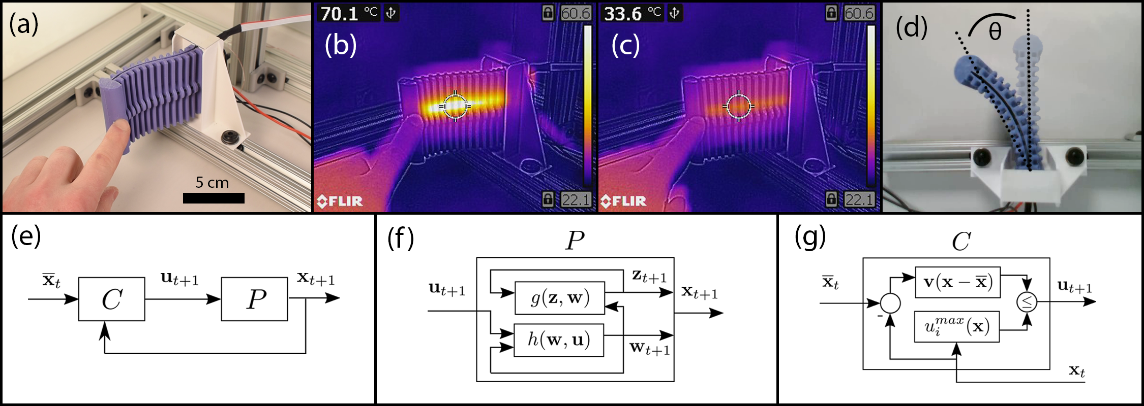
This article proposes a feedback control framework that ensures safety of a class of soft robot actuators. The framework employs a model-based supervisor in tandem with a primary, unspecified, control strategy - which we term the pose controller (Fig. 1(e)-(g)). We demonstrate our framework on a thermal shape memory alloy (SMA) actuator with two different pose controllers in the presence of environmental contact (Fig. 1(a)-(d)). This task presents a generalizable challenge as the cause of failure (excess heat) can only be indirectly monitored and controlled.
Specifically, this article contributes:
-
1.
A provably-safe, provably-stable supervisory controller for soft robot actuators modeled as affine systems,
-
2.
A provably-safe integration of the supervisor with any underlying pose controller, and
-
3.
A verification of the framework on a soft robot limb, maintaining safe actuator states, in an otherwise dangerous task.
1.1 Background: Robot Safety
Reliable use of robots in practical settings requires maintaining safe operation and consistent performance throughout their lifespan, regardless of environmental contact or human interaction [4, 5]. The informal concept of ‘safety’ as limiting force or position [13, 14, 15] is well-suited for soft robots, since mechanical conformability to contacting surfaces naturally restricts motions. Even when such limits are exceeded, some soft polymers can self-heal when mechanically damaged and recover their material properties [6, 9]. However, most soft robots rely on mechanism design for safety [16, 17, 18, 19], and there are only few examples of computational intelligence for verifiable behaviors [20].
In contrast, a formal specification of ‘safety’ is a set inclusion problem, where if a robot’s state remains within a certain set for all time then it is considered safe: the set is invariant under the system’s dynamics [21]. Computational techniques such as control barrier functions [22], model-predictive control [23], and formal verification [24] use this framework for safety verification. However, each approach comes with computation and implementation challenges, particularly the requirement of an accurate low-dimensional dynamics model, which is a longstanding challenge in soft robotics.
1.2 Soft Actuator Safety and Degradation
The unique material properties of actuators used in soft robotics introduce additional safety challenges: catastrophic pressure failures, high-temperatures and fire, or high-voltage arcing. As of yet, these dangers have been indirectly addressed by reducing actuation force [25] or by introducing design modifications [26]. Feedback control has also only indirectly addressed actuator safety, using approaches such as low impedance [27] without verification, open-loop planning [28, 29] only in known environments, or optimization-based control with only state constraints [30].
For SMA actuators in particular, prior work in safety has focused on sensing intrinsic actuator states (i.e. temperature) via inverting a constitutive model [31, 32] and applying a fixed threshold [33, 34, 10, 35], but these have not shown environmental contact [7] or formal verification. In addition to physical safety, SMA actuators are known to suffer from degradation due to thermal and mechanical cycling [36, 16, 37, 38], which when viewed as a temperature constraint [39] can also be formulated as a safe control problem.
1.3 Approach
Our framework considers dynamic saturation as a form of supervisory control, motivated by prior work that uses reachability computations to determine ‘activation’ of a supervisor [40]. This framework is a simplistic version of the formal supervisory controller framework [41, 42, 43] with only a single switching state.
Though our proposed approach makes a number of assumptions about the robot’s actuator dynamics, as are relevant to our use of SMA wires, it may be generalizable among a wider class of soft actuators. This article assumes one state per actuator, that the actuator states are independent, and that actuator dynamics are an affine system [29]. Other soft actuators may also be modeled by a single parameter, such as piston displacement in pneumatic or hydraulic actuators [44, 45], or cable retraction for cable-driven soft robots [46, 47, 48]. Our supervisor may also be adapted for nonlinear actuators via local linearizations and conservative parameter tuning. This article includes a study of our controller’s tuning parameter to assist in its application.
2 Supervisory Control for a Soft Robotic Actuator
Derivation of the supervisor’s controller proceeds below by presenting a dynamic saturation condition, then combining with a pose controller, and finally verifying safety.
2.1 System Model
The physical states of our particular SMA-powered robot include the robot body’s bending curvature and the actuators temperatures, described later in Sec. 3.2. For a formulation that is generally applicable to soft actuators of all kinds, we abstract these states into , consisting of the actuator states and states relating to the remainder of the system , as in , and some inputs . We assume dynamics of the form
| (1) |
where the actuator states influence the pose but not vice-versa. We again suggest that local linearization of coupled actuator-pose systems may enable equations of this form.
Our supervisory control system does not require knowledge of the pose dynamics , so no soft beam mechanics models are required here. We do assume that the discrete-time actuator dynamics are known, that our soft robot has one input per actuator state, and actuators that are uncoupled: there are actuators and
In addition, we assume that each actuator dynamics function is a linear (affine) system of the form
| (2) |
Dropping the indexing, consider each actuator’s system dynamics individually. We can use the affine augmentation to rewrite eqn. (2) as
| (3) |
where
| (4) |
The dynamics for each actuator, eqn. (3), are a linear single-input system, and we therefore can use linear system control techniques for the actuator itself despite the presumably nonlinear body dynamics .
2.2 The Supervisor’s Saturating Controller
Our problem statement considers a constraint on the actuator state of the form , i.e., a maximum operating limit. In the augmented form, this limit is . Consider first what magnitude of our input it would take to reach an arbitrary setpoint of this form, , at the next point in time given an observed state :
| (5) |
From linear systems theory, we have the celebrated result [49] that if is reachable from , it can be steered there in -many steps with minimum-energy cost by applying the input sequence
| (6) |
at each timestep in the horizon, where is the controllability Grammian for discrete-time systems:
| (7) |
and is the pseudoinverse.
For the aggressive case of one step ahead where , as implied by eqn. (5), substituting in the definition of the Grammian from eqn. (7) at the single timestep of becomes
| (8) |
Observe next that the actuator dynamics in eqn. (2) are a monotone control system [50], i.e., for two different inputs and applied at the same known state , dropping time index for brevity,
| (9) |
Intuitively, our actuator’s state has a lower value if we apply less input: less electrical power applied to our thermal muscles means lower temperature. Sec. 1 of the Supplementary Information S1 formally shows monotonicity.
A concept, then, to bring our system as close to as possible without exceeding would be to apply some fraction of this one step max, since . Choose a scalar multiplier for , which then gives a candidate feedback controller as
| (10) |
Closing the loop with this controller produces the autonomous dynamics of
| (11) |
Make the following substitution to analyze this system as a linear system, eliminating the affine setpoint offset:
| (12) |
Substitution into eqn. (11) gives
| (13) |
The equilibrium point under consideration for the closed-loop system of eqn. (13) is therefore
Notice this equilibrium point is not equal to our setpoint (). The inclusion of scales the equilibrium point in addition to slowing convergence. However, we can then select our such that our equilibrium point becomes the constraint boundary ,
| (14) | ||||
| (15) |
Combining, the full form of our supervisor’s feedback controller that takes the actuator state to the boundary of its constraint with a convergence rate of is
| (16) |
Lastly, we find the error dynamics by defining , and with some algebra on eqns. (13)-(15), the closed-loop response is
| (17) |
This is the same as eqn. (13), so the closed-loop system is stable if the open-loop system is stable and . See Supplementary Information S1 Sec. 2.1 for a proof.
2.3 Safety Verification of the Supervisor’s Controller
Operating the supervisor’s controller gives the dynamics in eqn. (17). We assume the closed-loop system has been designed via the criteria in the Supplementary Information S1 to be G.A.S., . However, even exponential stability does not necessarily guarantee that
| (18) |
For example, this safety condition would not hold for an underdamped SISO linear system.
Verifying the condition (18) can be done instead by calculating an invariant set for some given constraint [51, 52]. First, we pose the inequalities of the safety constraint as a polyhedron, noting that in terms of the error dynamics, safe operation holds if . Choose an arbitrary lower bound on the actuator state, , in order to consider operations on a closed set. This polyhedron can be expressed as
| (19) |
where
| (20) |
since the second element of is constrained to be identical to 1.
We then calculate a maximum positive invariant set , which contains all [52] the invariant sets such that given the closed-loop dynamics of eqn. (17). This iterative procedure uses the operation Pre(), which generates the set of all states which evolve into a set under the dynamics in one step:
| (21) |
A set is positive invariant under if and only if [51]. A more useful condition can be posed in terms of set equivalence:
which, with a polyhedral set, can be readily checked by comparing the constraints (e.g. the and of a set ).
Given the safety constraint in eqn. (19)-(20), the well-known Alg. 1 returns the set of initial conditions expressed as a polyhedron for which our system will remain within . We implemented Alg. 1 using the MPT3 Toolbox [53] in MATLAB. Executing Alg. 1 for our particular matrix (system identification of the SMA discussed below) with a variety of produced in every case; i.e., the iteration returned in one step. This expected behavior verifies safety, confirming our intuition that as long as our supervisor’s controller activates while the actuator state is , it will remain so (theoretically) for all time.
2.4 Supervisor Integration with Pose Controller
The controller in eqn. (16) drives our actuator states () to a maximum safe value. This section incorporates the supervisor in composition with another controller, which presumably feeds back the full robot state including pose.
So, assume there is a feedback controller , developed independently from the supervisor, that would close the loop of eqn. (1). Propose instead the following composition of and the supervisor:
| (22) | |||
| (23) |
where replaces the time indexing in eqn. (16) with feedback, noting the actuator state is part of the full state .
We note that this composed system is both continuous (in ) and Lipschitz continuous under certain conditions on . See Supplementary Information S1 Sec. 2.2 for a proof.
Finally, we show the most important property of , the safety verification that motivates all the work in this article.
Theorem 2.1.
Safety. Consider the closed-loop system defined by eqns. (1), (22)-(23), and the in eqn. (16) for all actuators . If Alg. 1 verifies that the set defined in eqns. (19)-(20) is positively invariant for the supervisor’s closed-loop error dynamics of eqn. (17), then is also invariant under , and
Proof 2.2.
Invariance of under the action of the supervisor’s controller alone, given by assumption, has proven that applying gives
| (24) |
Then by the definition of controller in eqn. (23), . Let the resulting actuator state from applying be . From the discussion above, is a monotone control system, and so applying gives
Remark. The above is a simple consequence of the same intuition as with the supervisor’s tuning parameter . For our example application of soft thermal actuators, applying less electrical power causes a lower temperature, and so applying less than a safe maximum of power will guarantee a safe temperature.
3 Hardware Testbed
The control system derived above is applicable for any soft robotic system whose equations of motion can be put in the form of eqn. (1)-(2). As one particular application, this article considers feedback control of a soft robotic limb constructed with thermally-actuated shape memory alloy (SMA) wire coils. Versions of this limb, previously developed as part of a soft underwater robot [11], have recently been deployed by the authors for both open-loop [29, 54] and closed-loop [55] control as a free-standing manipulator. For eventual application in locomotion, this article uses the proposed supervisory controller to maintain safe actuator states when significant and sustained contact occurs.
3.1 Hardware Design
Our soft limb consists of a bulk silicone body embedded with actuators and sensors (Fig. 2). The limb is designed for planar motions only in order to develop algorithms with a reduced-dimensional state space. The limb’s body (Smooth-On Smooth-Sil 945), shown in Fig. 2(a)(1), contains two embedded SMA wire coils (Dynalloy Flexinol, 0.020” wire diameter). The SMA wire coils are constrained by a ridge along the body’s horizontal axis, as shown in Fig. 2(a)(2) and Fig. 2(b)(2), so that actuation forces cause bending deflections.
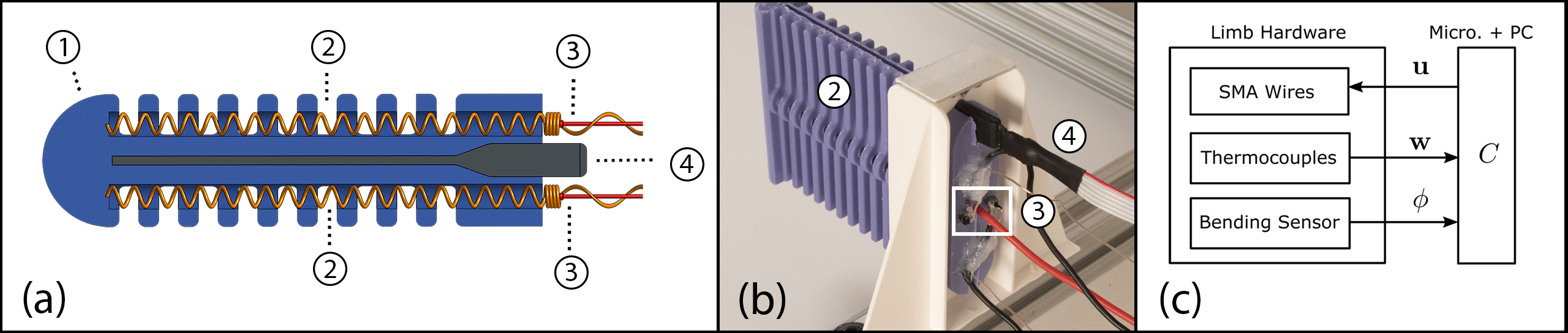
The two SMA wires are actuated through resistive (Joule) heating. Current through the wires was controlled using pulse-width modulation (PWM) to N-channel power MOSFETs connected to a 7V power supply. A microcontroller sets the PWM duty cycle.
Three sensors are located on the limb: one for the body’s pose, and one each for the temperatures of the wires. Temperature is sensed by thermocouples (Omega Engineering, type K, 30 AWG) affixed to the SMA coils at the rear of the limb using thermally conductive epoxy (MG 8329TCF) via the fabrication procedure described in our prior work [54], see Fig. 2(a)(3) and Fig. 2(b)(3). A soft capacitive bending sensor (Bendlabs, Inc.) is inserted into a groove in the limb (Fig. 2(a)(4) and Fig. 2(b)(4)), and provides a single measurement of angular deflection of the limb, , as shown in Fig. 1(d).
3.2 Robot and Actuator Model and Calibration
We use a simplified model of the limb for this article, with a state space of
| (25) |
where the body pose is deflection angle and actuator states are the temperatures of the two wires. Importantly, this article is not concerned with developing provably-stabilizing controllers for the body pose, and our supervisory controller in eqn. (16) does not require a model of body pose dynamics . Therefore, feedback of only the net deflection angle may be sufficient for pose control as in prior work on SMA-powered robots [56, 57, 31, 58].
The thermal dynamics of our SMA actuators can be approximated in the form of eqn. (2). As in prior work [29, 31], the first-principles model for Joule heating in discrete time is
| (26) |
for the -th SMA at time with specific heat capacity , ambient heat convection coefficient , surface area , and ambient temperature . The input electrical power, , is current controlled with , where is resistance and is current density. For our PWM input, we assume that the duty cycle modulates the fraction of time current is conducting through the SMA and that current is constant when flowing, so . Substituting and factoring out unknown constants into lumped coefficients,
| (27) |
4 Pose Feedback for an SMA-Powered Soft Robot
We employ two representative pose controllers for SMA-actuated robots in order to demonstrate that our supervisory control scheme is agnostic to choice of .
4.1 Antagonistic Actuation as a Single-Input, Single-Output System
Our supervisor is derived for an arbitrary number of soft actuators () in the form of eqn. (2). However, for our particular SMA-powered robot, prior research has shown that a pair of antagonistic actuators can be reformulated as a single-input, single-output (SISO) system [31, 59, 55]. We first note that the duty cycle input for each wire, , does not allow for a negative control input: we have no ability to cool the wire. However, since the actuators are oriented antagonistically, we can map one of the two SMA duty cycles to a negative range of a single scalar input, which we denote ,
| (28) | ||||
| (29) |
We therefore only need to specify a (bounded) SISO pose controller, .
4.2 PI with Anti-Windup
We first test a proportional-integral (PI) controller. We augment it with an anti-windup (AW) block [60] since our control saturates at . Defining as the difference between current vs. reference bending angle, implicitly indexing into , and with some minor abuses of notation for clarity, our PI-AW feedback controller takes the form:
| (30) | ||||
| (31) |
where the linear saturation function is defined as
| (32) |
Therefore, is the internal state for the anti-windup compensator, which tracks the difference between attempted versus applied control input. Tuning of the constants , and is discussed in Supplementary Information S1, Sec. 3.
4.3 Sliding Mode Controller with Boundary Layer
In addition to PI feedback as a standard approach, there has been much prior success in control of SMA-based robots and mechanisms using sliding mode control (SMC) [56, 57, 61]. SMC naturally addresses saturation issues, since switching occurs between some minimum and maximum input [62]. We employ a model-free sliding mode controller with a boundary layer, as suggested by Elahinia et al. [56], with a sliding surface , using a finite-difference approximation of derivative as
| (33) | ||||
| (34) |
where is the boundary layer thickness and is the phase plane angle [62]. Tuning of this controller is also discussed in S1 Sec. 3.
5 Supervisory Control Results
We perform three sets of tests to characterize and validate the action of the supervisor on the above controllers. In order to test our supervisor without permanently damaging the robot, we chose artificially low temperature constraints (between and ) for the tests.
5.1 Theoretical Performance Verification
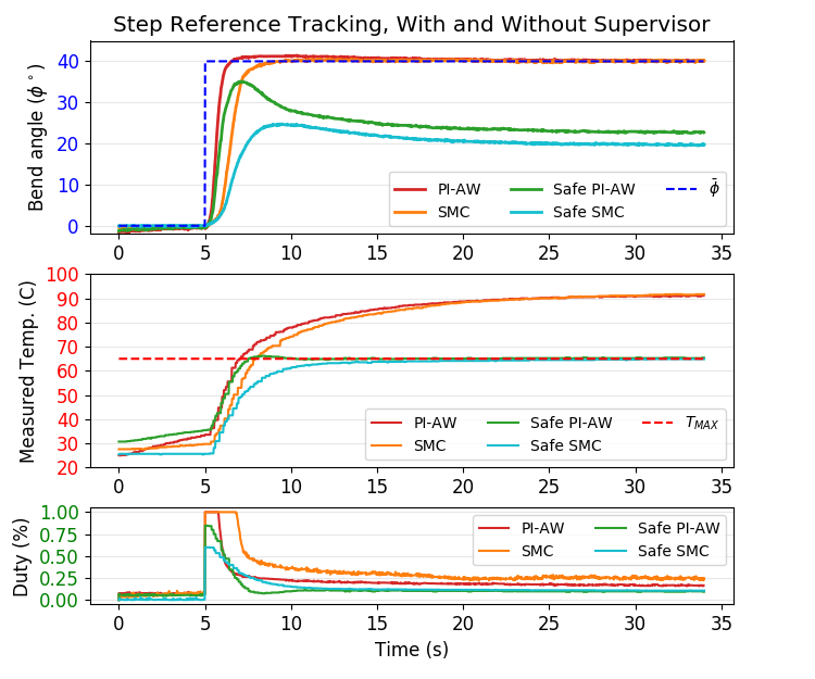
We first confirmed that our framework functions as intended by implementing both the PI-AW and SMC controllers, and comparing their operation with versus without the supervisor. We chose an arbitrary, but aggressive, step setpoint angle ( bending) and a maximum temperature of for the supervisor, with for conservative operation.
Fig. 3 and Supplementary Video S2 show the results of all four tests: both controllers, with versus without the supervisor. Both the PI-AW and SMC controllers, without the supervisor, regulate the limb around the desired setpoint with low error. However, both controllers cause the SMA wire temperatures to drift upwards, representing potentially unsafe operation. In contrast, the controllers with the supervisor included cause temperature to saturate at the maximum. This is the intended behavior: the supervisor’s activation sacrifices state tracking in favor of safe actuator states, and for all actuators. We conclude from these tests that the supervisor indeed operates independently of the underlying pose controller .
5.2 Supervisory Controller Tuning
Our next test, with and a max temperature of , executed the PI-AW controller with the supervisor for various values of its parameter . We only test using the PI-AW pose controller, since Fig. 3 shows similar activation behaviors for both pose controllers.
The data in Fig. 4 and Supplementary Video S3 demonstrate large variations in behavior depending on . For small values (), the supervisor activates almost as soon as control begins ( sec.), and temperature trajectories rise slowly but remain safe. For larger values (), the supervisor is much less aggressive. For the largest values, the limb briefly reaches the target before the supervisor forces a lower input. We do not report a result since its performance was poor.
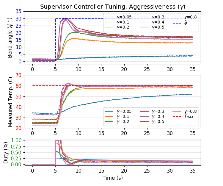
At larger values of , some violation of the safety constraint is observed, which is expected given our system identification of in eqn. (27). Unmodeled dynamics cause the value for to be artificially large. This suggests that smaller values are best in practice, since soft robot modeling is often imprecise.
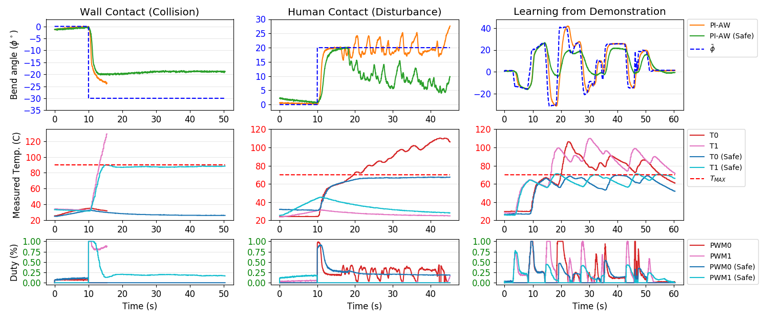
5.3 Physical Interactions
We finally stress-test our feedback method in three different physical interaction scenarios, each representing an eventual use of our soft limb. Each used the PI-AW controller for pose, with . These three scenarios, in Fig. 5, include environmental contact, human contact, and the attempted tracking of infeasible/unsafe trajectories. The first test (Fig. 5(a)) places a wall next to the limb that blocks it from reaching its target bend angle. In the second test (Fig. 5(a)), a human pushes on the robot, causing a disturbance.
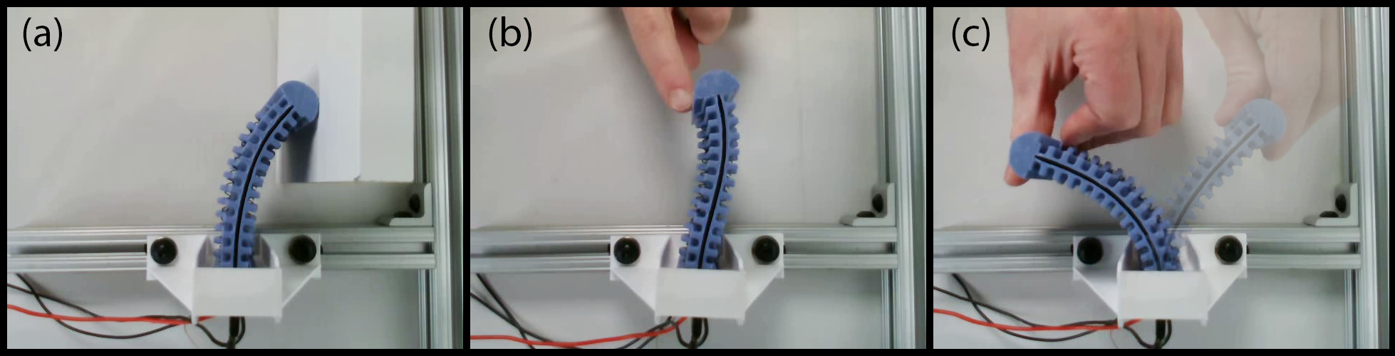
The final physical interaction example is tracking of a trajectory recorded beforehand by a human operator moving the limb, as in our prior work [29]. Substituting the recorded trajectory as attempts to recreate that motion, however unsafe it may be. With the supervisor, this procedure can be viewed as a crude form of learning from demonstration [63], where a feedback controller mimics a demonstrated action under safety/feasibility constraints.
The data from these tests are in Fig. 6, and demonstrations are shown in Supplementary Videos S4-S6. For the wall interaction, the unsafe control system without the supervisor heats the SMA wire rapidly and was manually deactivated before the test concluded, whereas the supervisor keeps the actuator at a steady maximum temperature. For the human disturbance, the unsafe controller responded dynamically to the disturbance, causing continued heating, whereas the test with the supervisor prevented a changing input during those motions and implicitly bounded the force applied to the human. Finally, for the “learning from demonstration” test, the unsafe controller was able to faithfully track the desired motion; however, the SMA temperatures violated constraints. The corresponding test with the supervisor demonstrates it dynamically activating and deactivating as both wires reach potentially unsafe operation.
6 Discussion
This article proposes a supervisory control scheme for a set of soft robot actuators that follow simple dynamics models, provably guaranteeing that actuator states remain in a safe region. The proposed supervisor is simple to formulate and implement, with very low online computational cost. Experiments show that the controller can be tuned for conservative operation even in the case when the actuator dynamics are a significant approximation, making the framework applicable for a variety of soft robot actuator designs. We demonstrate that the controller safely operates on a thermal actuator, maintaining safe temperatures in a variety of contact-rich environments.
This work highlights the inherent relationship between force applied at a manipulator tip and the bounds on its actuator state, for example, in the human contact disturbance test. Recent work has shown that environmental contact forces for a soft robot may be estimated simply from pose measurements [64]. Therefore, if a model for the body dynamics is available, it may be possible to convert between actuator bounds and body force bounds, allowing the concepts from this article to extend to safe interactions of body-to-environment: safety in pose as well as safety in actuator.
7 Future Work and Conclusion
Multiple directions of future work are anticipated to make the proposed framework more robust and applicable with fewer assumptions required. In particular, a probabilistic actuator dynamics model (and accompanying modifications to the controller) may provide better robustness when the linearization is poor. Similarly, future work will examine adaptive control for capturing unmodeled dynamics. If the actuator dynamics cannot be linearized, we will examine optimization techniques for the supervisor, such as model-predictive control. For robots with coupled actuator dynamics or more than one scalar state per actuator, future work may saturate actuators in terms of conic section bounds [50].
The system in this article relies on feedback for the supervisor, requiring sensors for all actuator states. However, if the actuator dynamics model sufficiently captures the underlying physical phenomena, it may be possible to estimate the states for use in the supervisor, eliminating the need for external sensing.
Lastly, a major motivation of this article is applying feedback control to soft robots in locomotion tasks. We plan to implement our supervisor on SMA-actuated walking soft robots [11] to demonstrate safe, closed-loop, locomotion in state-feedback. Safe locomotion with feedback will bring soft robots closer to real-world deployment and positive demonstrations of their applicability to real-world tasks.
Acknowledgements
We thank Xiaonan Huang, Richard Desatnik, and all members of the Soft Machines Lab at CMU for their collaboration in the design framework for the robot studied in this article.
Author Contribution Statement
APS: Conceptualization, Formal Analysis, Methodology, Software, Funding Acquisition, Writing - original draft. ZJP: Methodology, Software, Writing - review and editing. ATW: Methodology, Software, Writing - review and editing. CM: Funding Acquisition, Supervision, Writing - review and editing.
Author Disclosure Statement
No competing financial interests exist.
Funding Information
This work was in part supported by the Office of Naval Research under Grant No. N000141712063 (PM: Dr. Tom McKenna), the National Oceanographic Partnership Program (NOPP) under Grant No. N000141812843 (PM: Dr. Reginald Beach), and an Intelligence Community Postdoctoral Research Fellowship through the Oak Ridge Institute for Science and Education.
Supplementary Material
Supplementary Information S1
Supplementary Video S2
Supplementary Video S3
Supplementary Video S4
Supplementary Video S5
Supplementary Video S6
References
- Laschi et al. [2016] Cecilia Laschi, Barbara Mazzolai, and Matteo Cianchetti. Soft robotics: Technologies and systems pushing the boundaries of robot abilities. Science Robotics, 1(1):eaah3690, December 2016. ISSN 2470-9476. 10.1126/scirobotics.aah3690. URL http://robotics.sciencemag.org/lookup/doi/10.1126/scirobotics.aah3690.
- Majidi [2014] Carmel Majidi. Soft Robotics: A Perspective - Current Trends and Prospects for the Future. Soft Robotics, 1(1):5–11, March 2014. ISSN 2169-5172. 10.1089/soro.2013.0001. URL https://www.liebertpub.com/doi/10.1089/soro.2013.0001.
- Zhang et al. [2019a] Jun Zhang, Jun Sheng, Ciarán T. O’Neill, Conor J. Walsh, Robert J. Wood, Jee-Hwan Ryu, Jaydev P. Desai, and Michael C. Yip. Robotic Artificial Muscles: Current Progress and Future Perspectives. IEEE Transactions on Robotics, 35(3):761–781, June 2019a. ISSN 1941-0468. 10.1109/TRO.2019.2894371.
- Vasic and Billard [2013] Milos Vasic and Aude Billard. Safety issues in human-robot interactions. In 2013 IEEE International Conference on Robotics and Automation, pages 197–204, May 2013. 10.1109/ICRA.2013.6630576.
- Dhillon et al. [2002] B.S. Dhillon, A.R.M. Fashandi, and K.L. Liu. Robot systems reliability and safety: A review. Journal of Quality in Maintenance Engineering, 8(3):170–212, January 2002. ISSN 1355-2511. 10.1108/13552510210439784.
- Terryn et al. [2017] Seppe Terryn, Joost Brancart, Dirk Lefeber, Guy Van Assche, and Bram Vanderborght. Self-healing soft pneumatic robots. Science Robotics, 2(9):eaan4268, August 2017. 10.1126/scirobotics.aan4268.
- Soother et al. [2020] Dileep Kumar Soother, Jawaid Daudpoto, and Bhawani Shankar Chowdhry. Challenges for practical applications of shape memory alloy actuators. Materials Research Express, 7(7):073001, July 2020. ISSN 2053-1591. 10.1088/2053-1591/aba403. URL https://doi.org/10.1088/2053-1591/aba403.
- Plante and Dubowsky [2006] Jean-Sébastien Plante and Steven Dubowsky. Large-scale failure modes of dielectric elastomer actuators. International Journal of Solids and Structures, 43(25-26):7727–7751, December 2006. ISSN 00207683. 10.1016/j.ijsolstr.2006.03.026.
- Bilodeau and Kramer [2017] R. Adam Bilodeau and Rebecca K. Kramer. Self-Healing and Damage Resilience for Soft Robotics: A Review. Frontiers in Robotics and AI, 4:48, 2017. ISSN 2296-9144. 10.3389/frobt.2017.00048.
- Yee Harn Teh and Featherstone [2008] Yee Harn Teh and Roy Featherstone. An Architecture for Fast and Accurate Control of Shape Memory Alloy Actuators. The International Journal of Robotics Research, 27(5):595–611, May 2008. ISSN 0278-3649, 1741-3176. 10.1177/0278364908090951.
- Patterson et al. [2020] Zach J. Patterson, Andrew P. Sabelhaus, Keene Chin, Tess Hellebrekers, and Carmel Majidi. An Untethered Brittle Star-Inspired Soft Robot for Closed-Loop Underwater Locomotion. In 2020 IEEE/RSJ International Conference on Intelligent Robots and Systems (IROS), pages 8758–8764, October 2020. 10.1109/IROS45743.2020.9341008. ISSN: 2153-0866.
- Huang et al. [2019a] Xiaonan Huang, Kitty Kumar, Mohammad Khalid Jawed, Zisheng Ye, and Carmel Majidi. Soft Electrically Actuated Quadruped (SEAQ)—Integrating a Flex Circuit Board and Elastomeric Limbs for Versatile Mobility. IEEE Robotics and Automation Letters, 4(3):2415–2422, July 2019a. ISSN 2377-3766. 10.1109/LRA.2019.2903856. URL https://ieeexplore.ieee.org/document/8663413/. tex.publisher: IEEE.
- Lasota et al. [2017] Przemyslaw A. Lasota, Terrence Fong, and Julie A. Shah. A Survey of Methods for Safe Human-Robot Interaction. Foundations and Trends in Robotics, 5(4):261–349, May 2017. ISSN 1935-8253, 1935-8261. 10.1561/2300000052. URL https://www.nowpublishers.com/article/Details/ROB-052.
- Zanchettin et al. [2016] Andrea Maria Zanchettin, Nicola Maria Ceriani, Paolo Rocco, Hao Ding, and Björn Matthias. Safety in human-robot collaborative manufacturing environments: Metrics and control. IEEE Transactions on Automation Science and Engineering, 13(2):882–893, April 2016. ISSN 1558-3783. 10.1109/TASE.2015.2412256.
- Tonietti et al. [2005] G. Tonietti, R. Schiavi, and A. Bicchi. Design and Control of a Variable Stiffness Actuator for Safe and Fast Physical Human/Robot Interaction. In Proceedings of the 2005 IEEE International Conference on Robotics and Automation, pages 526–531, April 2005. 10.1109/ROBOT.2005.1570172.
- Villanueva et al. [2011] Alex Villanueva, Colin Smith, and Shashank Priya. A biomimetic robotic jellyfish (Robojelly) actuated by shape memory alloy composite actuators. Bioinspiration & Biomimetics, 6(3):036004, September 2011. ISSN 1748-3182, 1748-3190. 10.1088/1748-3182/6/3/036004.
- Colorado et al. [2012] J Colorado, A Barrientos, C Rossi, and K S Breuer. Biomechanics of smart wings in a bat robot: Morphing wings using SMA actuators. Bioinspiration & Biomimetics, 7(3):036006, September 2012. ISSN 1748-3182, 1748-3190. 10.1088/1748-3182/7/3/036006.
- White et al. [2018] Edward L. White, Jennifer C. Case, and Rebecca Kramer-Bottiglio. A Soft Parallel Kinematic Mechanism. Soft Robotics, 5(1):36–53, February 2018. ISSN 2169-5172, 2169-5180. 10.1089/soro.2017.0033.
- Huang et al. [2019b] Xiaonan Huang, Kitty Kumar, Mohammad K. Jawed, Amir Mohammadi Nasab, Zisheng Ye, Wanliang Shan, and Carmel Majidi. Highly Dynamic Shape Memory Alloy Actuator for Fast Moving Soft Robots. Advanced Materials Technologies, 4(4):1800540, 2019b. ISSN 2365-709X. 10.1002/admt.201800540.
- Balasubramanian et al. [2020] Lavanya Balasubramanian, Tom Wray, and Dana D. Damian. Fault Tolerant Control in Shape-Changing Internal Robots. In 2020 IEEE International Conference on Robotics and Automation (ICRA), pages 5502–5508, May 2020. 10.1109/ICRA40945.2020.9196989. ISSN: 2577-087X.
- Dang and Maler [1998] Thao Dang and Oded Maler. Reachability analysis via face lifting. In Thomas A. Henzinger and Shankar Sastry, editors, Hybrid Systems: Computation and Control, Lecture Notes in Computer Science, pages 96–109, Berlin, Heidelberg, 1998. Springer. ISBN 978-3-540-69754-1. 10.1007/3-540-64358-3_34.
- Ames et al. [2017] Aaron D. Ames, Xiangru Xu, Jessy W. Grizzle, and Paulo Tabuada. Control Barrier Function Based Quadratic Programs for Safety Critical Systems. IEEE Transactions on Automatic Control, 62(8):3861–3876, August 2017. ISSN 1558-2523. 10.1109/TAC.2016.2638961.
- Massera Filho et al. [2017] Carlos Massera Filho, Marco H. Terra, and Denis F. Wolf. Safe Optimization of Highway Traffic With Robust Model Predictive Control-Based Cooperative Adaptive Cruise Control. IEEE Transactions on Intelligent Transportation Systems, 18(11):3193–3203, November 2017. ISSN 1558-0016. 10.1109/TITS.2017.2679098.
- Mitra et al. [2003] Sayan Mitra, Yong Wang, Nancy Lynch, and Eric Feron. Safety Verification of Model Helicopter Controller Using Hybrid Input/Output Automata. In Hybrid Systems: Computation and Control, Lecture Notes in Computer Science, pages 343–358, Berlin, Heidelberg, 2003. Springer. ISBN 978-3-540-36580-8. 10.1007/3-540-36580-X_26.
- Stilli et al. [2017] Agostino Stilli, Helge A. Wurdemann, and Kaspar Althoefer. A Novel Concept for Safe, Stiffness-Controllable Robot Links. Soft Robotics, 4(1):16–22, March 2017. ISSN 2169-5172. 10.1089/soro.2016.0015. URL https://www.liebertpub.com/doi/full/10.1089/soro.2016.0015. Publisher: Mary Ann Liebert, Inc., publishers.
- Shin et al. [2014] Dongjun Shin, Xiyang Yeh, and Oussama Khatib. A new hybrid actuation scheme with artificial pneumatic muscles and a magnetic particle brake for safe human–robot collaboration. The International Journal of Robotics Research, 33(4):507–518, April 2014. ISSN 0278-3649. 10.1177/0278364913509858. URL https://doi.org/10.1177/0278364913509858. Publisher: SAGE Publications Ltd STM.
- Whitney et al. [2016] John P. Whitney, Tianyao Chen, John Mars, and Jessica K. Hodgins. A hybrid hydrostatic transmission and human-safe haptic telepresence robot. In 2016 IEEE International Conference on Robotics and Automation (ICRA), pages 690–695, May 2016. 10.1109/ICRA.2016.7487195.
- Sabelhaus et al. [2020] Andrew P. Sabelhaus, Albert H. Li, Kimberly A. Sover, Jacob R. Madden, Andrew R. Barkan, Adrian K. Agogino, and Alice M. Agogino. Inverse Statics Optimization for Compound Tensegrity Robots. IEEE Robotics and Automation Letters, 5(3):3982–3989, July 2020. ISSN 2377-3766. 10.1109/LRA.2020.2983699.
- Wertz et al. [2022] Anthony Wertz, Andrew P. Sabelhaus, and Carmel Majidi. Trajectory Optimization for Thermally-Actuated Soft Planar Robot Limbs. In 2022 IEEE 5th International Conference on Soft Robotics (RoboSoft), pages 439–446, April 2022. 10.1109/RoboSoft54090.2022.9762226.
- Sabelhaus et al. [2021] Andrew P. Sabelhaus, Huajing Zhao, Edward L. Zhu, Adrian K. Agogino, and Alice M. Agogino. Model-Predictive Control With Inverse Statics Optimization for Tensegrity Spine Robots. IEEE Transactions on Control Systems Technology, 29(1):263–277, January 2021. ISSN 1558-0865. 10.1109/TCST.2020.2975138.
- Ho and Desai [2013] Mingyen Ho and Jaydev P. Desai. Modeling, characterization and control of antagonistic SMA springs for use in a neurosurgical robot. In 2013 IEEE International Conference on Robotics and Automation, pages 2503–2508, May 2013. 10.1109/ICRA.2013.6630918.
- Russell and Gorbet [1995] R.A. Russell and R.B. Gorbet. Improving the response of SMA actuators. In Proceedings of 1995 IEEE International Conference on Robotics and Automation, volume 3, pages 2299–2304 vol.3, May 1995. 10.1109/ROBOT.1995.525604.
- Kuribayashi [1991] Katsutoshi Kuribayashi. Improvement of the Response of an SMA Actuator Using a Temperature Sensor. The International Journal of Robotics Research, 10(1):13–20, February 1991. ISSN 0278-3649. 10.1177/027836499101000102. URL https://doi.org/10.1177/027836499101000102.
- Liu et al. [2019] Mingfang Liu, Lina Hao, Wei Zhang, Yang Chen, and Jiaming Chen. Reinforcement Learning Control of a Shape Memory Alloy-based Bionic Robotic Hand. In 2019 IEEE 9th Annual International Conference on CYBER Technology in Automation, Control, and Intelligent Systems (CYBER), pages 969–973, July 2019. 10.1109/CYBER46603.2019.9066775.
- Jin et al. [2016] Hu Jin, Erbao Dong, Gursel Alici, Shixin Mao, Xu Min, Chunshan Liu, K H Low, and Jie Yang. A starfish robot based on soft and smart modular structure (SMS) actuated by SMA wires. Bioinspiration & Biomimetics, 11(5):056012, September 2016. ISSN 1748-3190. 10.1088/1748-3190/11/5/056012.
- Sofla et al. [2008] A. Y. N. Sofla, D. M. Elzey, and H. N. G. Wadley. Cyclic degradation of antagonistic shape memory actuated structures. Smart Materials and Structures, 17(2):025014, February 2008. ISSN 0964-1726. 10.1088/0964-1726/17/2/025014. URL https://doi.org/10.1088/0964-1726/17/2/025014.
- Mohd Jani et al. [2014] Jaronie Mohd Jani, Martin Leary, Aleksandar Subic, and Mark A. Gibson. A review of shape memory alloy research, applications and opportunities. Materials & Design (1980-2015), 56:1078–1113, April 2014. ISSN 0261-3069. 10.1016/j.matdes.2013.11.084.
- Chin et al. [2020] Keene Chin, Tess Hellebrekers, and Carmel Majidi. Machine Learning for Soft Robotic Sensing and Control. Advanced Intelligent Systems, 2(6):1900171, 2020. ISSN 2640-4567. 10.1002/aisy.201900171.
- Van Humbeeck [1991] J. Van Humbeeck. Cycling Effects, Fatigue and Degradation of Shape Memory Alloys. Le Journal de Physique IV, 01(C4):C4–189–C4–197, November 1991. ISSN 1155-4339. 10.1051/jp4:1991429.
- Zhang et al. [2019b] Yichen Zhang, M. Ehsan Raoufat, Kevin Tomsovic, and Seddik M. Djouadi. Set Theory-Based Safety Supervisory Control for Wind Turbines to Ensure Adequate Frequency Response. IEEE Transactions on Power Systems, 34(1):680–692, January 2019b. ISSN 1558-0679. 10.1109/TPWRS.2018.2867825.
- Qi et al. [2015] Yiwen Qi, Wen Bao, and Juntao Chang. State-Based Switching Control Strategy with Application to Aeroengine Safety Protection. Journal of Aerospace Engineering, 28(3):04014076, May 2015. ISSN 1943-5525. 10.1061/(ASCE)AS.1943-5525.0000405. URL https://ascelibrary.org/doi/abs/10.1061/%28ASCE%29AS.1943-5525.0000405.
- Colombo and Del Vecchio [2011] Alessandro Colombo and Domitilla Del Vecchio. Supervisory control of differentially flat systems based on abstraction. In 2011 50th IEEE Conference on Decision and Control and European Control Conference, pages 6134–6139, December 2011. 10.1109/CDC.2011.6160759.
- Dulce-Galindo et al. [2019] J. A. Dulce-Galindo, Marcelo A. Santos, Guilherme V. Raffo, and Patrícia N. Pena. Autonomous Navigation of Multiple Robots using Supervisory Control Theory. In 2019 18th European Control Conference (ECC), pages 3198–3203, June 2019. 10.23919/ECC.2019.8796261.
- Marchese et al. [2015] Andrew D. Marchese, Russ Tedrake, and Daniela Rus. Dynamics and trajectory optimization for a soft spatial fluidic elastomer manipulator. In 2015 IEEE International Conference on Robotics and Automation (ICRA), pages 2528–2535, May 2015. 10.1109/ICRA.2015.7139538.
- Stölzle and Santina [2021] Maximilian Stölzle and Cosimo Della Santina. Piston-Driven Pneumatically-Actuated Soft Robots: modeling and backstepping control. IEEE Control Systems Letters, 2021. ISSN 2475-1456. 10.1109/LCSYS.2021.3134165.
- Gravagne et al. [2003] I.A. Gravagne, C.D. Rahn, and I.D. Walker. Large deflection dynamics and control for planar continuum robots. IEEE/ASME Transactions on Mechatronics, 8(2):299–307, June 2003. ISSN 1941-014X. 10.1109/TMECH.2003.812829.
- Renda et al. [2012] F Renda, M Cianchetti, M Giorelli, A Arienti, and C Laschi. A 3D steady-state model of a tendon-driven continuum soft manipulator inspired by the octopus arm. Bioinspiration & Biomimetics, 7(2):025006, June 2012. ISSN 1748-3182, 1748-3190. 10.1088/1748-3182/7/2/025006.
- Jarrett and McDaid [2017] C. Jarrett and A. J. McDaid. Robust Control of a Cable-Driven Soft Exoskeleton Joint for Intrinsic Human-Robot Interaction. IEEE Transactions on Neural Systems and Rehabilitation Engineering, 25(7):976–986, July 2017. ISSN 1558-0210. 10.1109/TNSRE.2017.2676765.
- Baggio et al. [2019] Giacomo Baggio, Vaibhav Katewa, and Fabio Pasqualetti. Data-Driven Minimum-Energy Controls for Linear Systems. IEEE Control Systems Letters, 3(3):589–594, July 2019. ISSN 2475-1456. 10.1109/LCSYS.2019.2914090.
- Angeli and Sontag [2003] D. Angeli and E.D. Sontag. Monotone control systems. IEEE Transactions on Automatic Control, 48(10):1684–1698, October 2003. ISSN 1558-2523. 10.1109/TAC.2003.817920.
- Gilbert and Tan [1991] E.G. Gilbert and K.T. Tan. Linear systems with state and control constraints: the theory and application of maximal output admissible sets. IEEE Transactions on Automatic Control, 36(9):1008–1020, September 1991. ISSN 1558-2523. 10.1109/9.83532.
- Blanchini [1999] F. Blanchini. Set invariance in control. Automatica, 35(11):1747–1767, November 1999. ISSN 0005-1098. 10.1016/S0005-1098(99)00113-2. URL https://www.sciencedirect.com/science/article/pii/S0005109899001132.
- Herceg et al. [2013] M. Herceg, M. Kvasnica, C.N. Jones, and M. Morari. Multi-Parametric Toolbox 3.0. In Proc. of the European Control Conference, pages 502–510, Zürich, Switzerland, July 17–19 2013. http://control.ee.ethz.ch/~mpt.
- Sabelhaus et al. [2022] Andrew P. Sabelhaus, Rohan K. Mehta, Anthony T. Wertz, and Carmel Majidi. In-Situ Sensing and Dynamics Predictions for Electrothermally-Actuated Soft Robot Limbs. Frontiers in Robotics and AI, 9, 2022. ISSN 2296-9144. URL https://www.frontiersin.org/article/10.3389/frobt.2022.888261.
- Patterson et al. [2022] Zach J. Patterson, Andrew P. Sabelhaus, and Carmel Majidi. Robust Control of a Multi-Axis Shape Memory Alloy-Driven Soft Manipulator. IEEE Robotics and Automation Letters, 7(2):2210–2217, April 2022. ISSN 2377-3766. 10.1109/LRA.2022.3143256.
- Elahinia and Ashrafiuon [2002] Mohammad H. Elahinia and Hashem Ashrafiuon. Nonlinear Control of a Shape Memory Alloy Actuated Manipulator. Journal of Vibration and Acoustics, 124(4):566–575, October 2002. ISSN 1048-9002. 10.1115/1.1501285. URL https://asmedigitalcollection.asme.org/vibrationacoustics/article/124/4/566/463466/Nonlinear-Control-of-a-Shape-Memory-Alloy-Actuated.
- Jin et al. [2015] Maolin Jin, Jinoh Lee, and Kyung Kwan Ahn. Continuous Nonsingular Terminal Sliding-Mode Control of Shape Memory Alloy Actuators Using Time Delay Estimation. IEEE/ASME Transactions on Mechatronics, 20(2):899–909, April 2015. ISSN 1941-014X. 10.1109/TMECH.2014.2323897.
- Grant and Hayward [1997] Danny Grant and Vincent Hayward. Variable structure control of shape memory alloy actuators. IEEE Control Systems Magazine, 17(3):80–88, June 1997. ISSN 1066-033X. 10.1109/37.588180. URL https://ieeexplore.ieee.org/document/588180/.
- Prechtl et al. [2020] Johannes Prechtl, Stefan Seelecke, Paul Motzki, and Gianluca Rizzello. Self-Sensing Control of Antagonistic SMA Actuators Based on Resistance-Displacement Hysteresis Compensation. In ASME 2020 Conference on Smart Materials, Adaptive Structures and Intelligent Systems. American Society of Mechanical Engineers Digital Collection, November 2020. 10.1115/SMASIS2020-2224. URL https://memagazineselect.asmedigitalcollection.asme.org/SMASIS/proceedings/SMASIS2020/84027/V001T03A001/1090347.
- Åström et al. [2006] Karl Johan Åström, Tore Hägglund, and Karl J Astrom. Advanced PID control, volume 461. ISA-The Instrumentation, Systems, and Automation Society, 2006.
- Wiest and Buckner [2014] Jennifer Hannen Wiest and Gregory D. Buckner. Indirect Intelligent Sliding Mode Control of Antagonistic Shape Memory Alloy Actuators Using Hysteretic Recurrent Neural Networks. IEEE Transactions on Control Systems Technology, 22(3):921–929, May 2014. ISSN 1558-0865. 10.1109/TCST.2013.2272420.
- Slotine et al. [1991] Jean-Jacques E Slotine, Weiping Li, et al. Applied nonlinear control. Prentice hall Englewood Cliffs, NJ, 1991.
- Argall et al. [2009] Brenna D. Argall, Sonia Chernova, Manuela Veloso, and Brett Browning. A survey of robot learning from demonstration. Robotics and Autonomous Systems, 57(5):469–483, May 2009. ISSN 0921-8890. 10.1016/j.robot.2008.10.024. URL https://www.sciencedirect.com/science/article/pii/S0921889008001772.
- Della Santina et al. [2020] Cosimo Della Santina, Ryan Landon Truby, and Daniela Rus. Data–Driven Disturbance Observers for Estimating External Forces on Soft Robots. IEEE Robotics and Automation Letters, 5(4):5717–5724, October 2020. ISSN 2377-3766. 10.1109/LRA.2020.3010738.