Further author information: (Send correspondence to K.V.G)
K.V.G.: E-mail: kvangorkom@arizona.edu
The space coronagraph optical bench (SCoOB): 2. wavefront sensing and control in a vacuum-compatible coronagraph testbed for spaceborne high-contrast imaging technology
Abstract
The 2020 Decadal Survey on Astronomy and Astrophysics endorsed space-based high contrast imaging for the detection and characterization of habitable exoplanets as a key priority for the upcoming decade. To advance the maturity of starlight suppression techniques in a space-like environment, we are developing the Space Coronagraph Optical Bench (SCoOB) at the University of Arizona, a new thermal vacuum (TVAC) testbed based on the Coronagraphic Debris Exoplanet Exploring Payload (CDEEP), a SmallSat mission concept for high contrast imaging of circumstellar disks in scattered light. When completed, the testbed will combine a vector vortex coronagraph (VVC) with a Kilo-C microelectromechanical systems (MEMS) deformable mirror from Boston Micromachines Corp (BMC) and a self-coherent camera (SCC) with a goal of raw contrast surpassing at visible wavelengths. In this proceedings, we report on our wavefront sensing and control efforts on this testbed in air, including the as-built performance of the optical system and the implementation of algorithms for focal-plane wavefront control and digging dark holes (regions of high contrast in the focal plane) using electric field conjugation (EFC) and related algorithms.
keywords:
high contrast imaging, coronagraphy, wavefront sensing and control, deformable mirrors1 INTRODUCTION
Future space observatories tasked with the goal of detecting and characterizing earth-like exoplanets will require coronagraphs and wavefront control algorithms capable of achieving and maintaining contrasts on the order of . To aid in the maturation program for high contrast imaging technology, we are developing the space coronagraph optical bench (SCoOB) at the University of Arizona Space Astrophysics Lab (UASAL), a thermal vacuum high contrast imaging testbed designed to enable demonstrations of starlight suppression techniques in a space-like environment. In this report, we describe our initial wavefront sensing and control efforts on the testbed.
2 Testbed overview
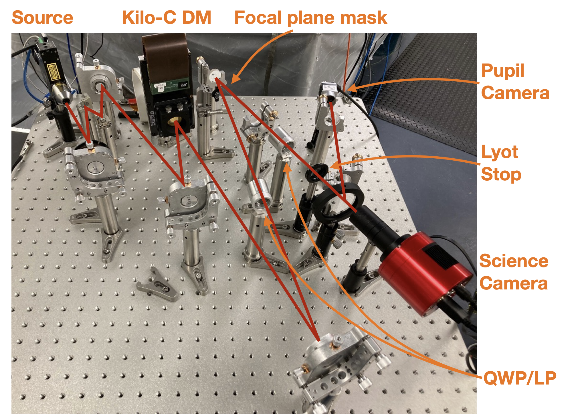
A brief overview of the key features of the testbed is given here. Details of the initial optical design are given in Maier et al. 2020[1] and the updated design, assembly, and initial as-built performance are described in Ashcraft et al. 2022[2].
Deformable mirror: The system DM is a Kilo-C 1.5-stroke MEMS device from BMC with 952 actuators and one non-responsive actuator. The beam footprint at the DM plane is approximately 9.6mm for 32 actuators across the pupil.
Focal plane masks: An image plane in an f/47 beam downstream of the DM is available for focal plane masks (FPMs). Initial experiments on the testbed have primarily made use of a knife-edge FPM. A triple-grating charge-6 vector vortex coronagraph (TGVVC)[3] is currently installed for testing. Some initial lab measurements with the TGVVC are presented in Doelman et al. 2022[4]. Additional VVC [5, 6] devices from BEAM Co are being procured.
Lyot stop: A 95% Lyot stop (LS) is installed for starlight suppression in concert with the FPM. The Lyot stop includes a pinhole outside the geometric pupil for self-coherent camera (SCC)[7] experiments. A tolerancing analysis of the SCC is presented in Derby et al. 2022[8].
Cameras: The focal-plane science camera is an ASI294MM Pro CMOS device with 2.32 pixels and 1.2-7.3e- read noise in an f/18 beam. A pellicle downstream of the LS relays the beam to a Basler acA2500-60um camera in a pupil plane.
Source: The current source is a PD-LD SLM-632.8 frequency-stabilized laser diode that outputs 22mW of power.
Software: The cacao[9] package forms the basis of the testbed control software, with additional packages inherited from MagAO-X[10]. Most closed-loop control operations are performed via Python interfaces with shared memory images in cacao.
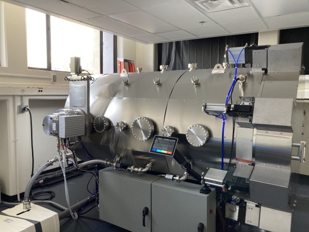
The testbed is currently operated in-air on a pneumatic optical table but will be moved into a thermal vacuum (TVAC) chamber later in 2022.
 |
3 Strehl ratio optimization
Prior to digging any dark holes, we employ a phase retrieval (PR) algorithm in closed-loop with the DM to drive out phase aberrations and maximize the testbed Strehl ratio.
The voltage bias that maximizes the inter-actuator stroke on a Kilo-C device is found around 70%; however, provided that the commands required to clean up the wavefront and dig a dark hole are not limited by stroke, it may be more optimal to take advantage of the approximately quadratic stroke-voltage relationship and choose a smaller operating bias to lower the contrast floor that arises from discretization effects. Following the analysis in Ruane et al. 2020 [11], we estimate the contrast floor due to our 14-bit COTS drive electronics and Kilo-C DM. We apply an extra factor of 2 to account for the discrepancy found between the analytical and measured contrast floor. With a gain of 8.7 nm/V at 70% bias, we expect a floor of ; at 40%, our device has a gain of 2.9 nm/V for a contrast floor of . We choose this latter bias around which to flatten the DM.
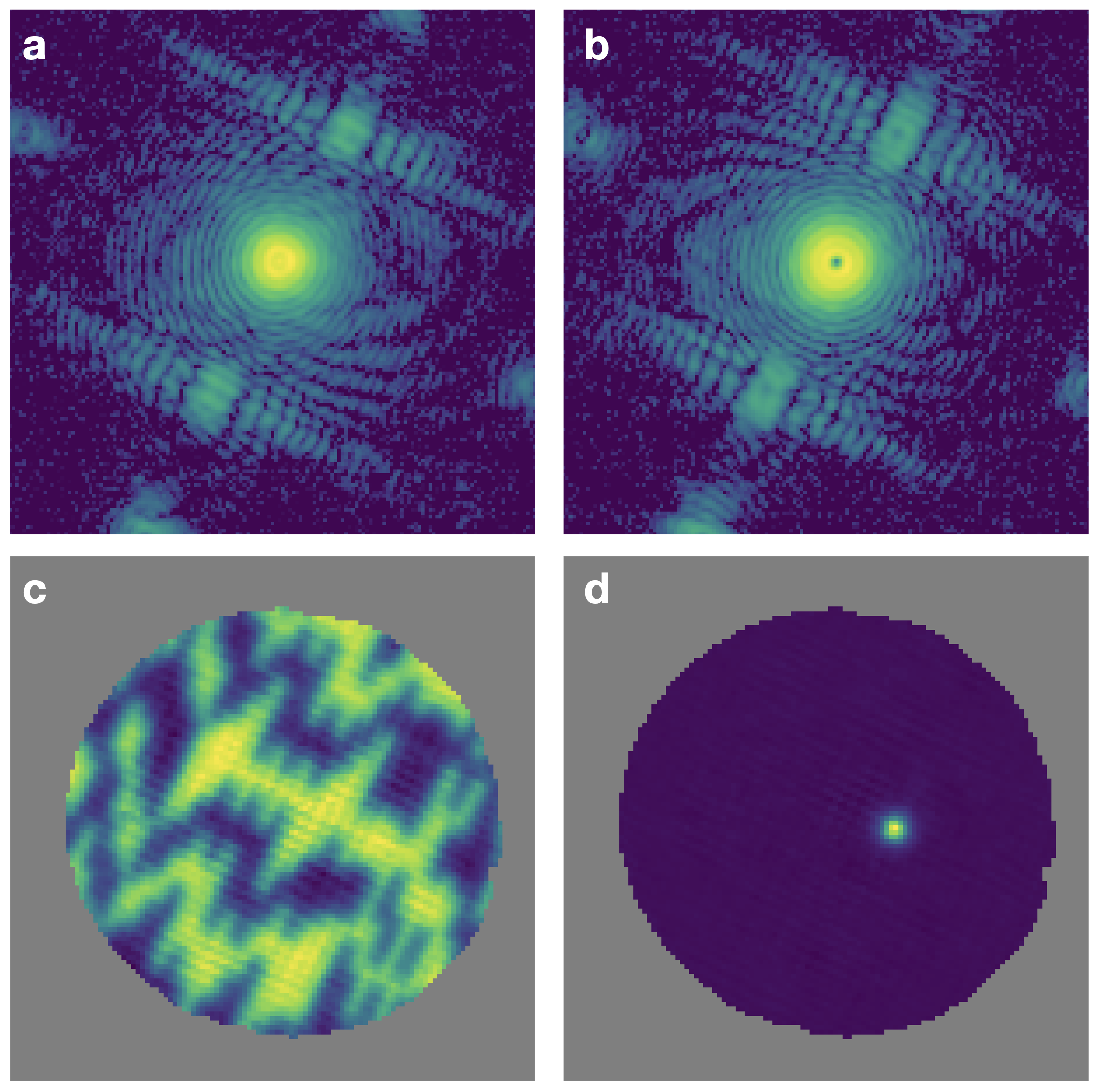
We employ a parametric phase retrieval algorithm adapted from Thurman et al. 2009[12] and implemented on MagAO-X [13] but modified to replace the angular spectrum propagation to defocused planes with a pair of defocus probes on the DM. We calibrate the PR response matrix similar to the procedure described in Van Gorkom et al. 2021 [13] but employ a set of Hadamard probes on the DM to calibrate the system [14] in place of grid patterns. Actuators outside the beam footprint on the DM are removed from the calculated control matrix and commanded to the mean of nearest-neighbor actuators. Examples of the measured probed PSFs, phase estimates of the Hadamard modes, and reconstructed influence functions are shown in Figure 2.
 |
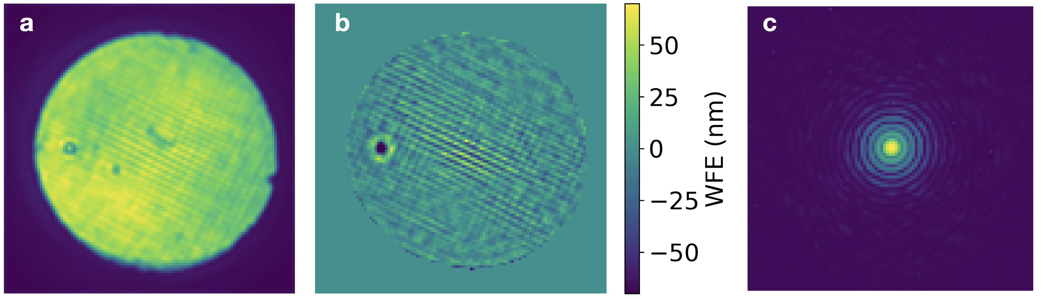
A typical example of a retrieved phase map after closed loop wavefront optimization is shown in Figure 3, along with a measurement of the optimized PSF. We estimate a residual wavefront of approximately 10 nm RMS, and a Strehl ratio of 0.95. The amplitude of our defocus diversity is relatively small ( wave) and limited by the DM stroke available from the 40% voltage bias, which suggests our PR has reduced sensitivity to high-order aberrations [15], likely resulting in somewhat optimistic estimates of the residual wavefront RMS and Strehl ratio.
 |
4 Wavefront control for high contrast imaging
Initial demonstrations of high contrast imaging on the testbed employed a knife-edge FPM combined with a Lyot stop and a HeNe laser at nm. The knife-edge was aligned to block out to 1-2 . Since we have only a single DM in the system, we dig only one-sided DHs.
To dig a dark hole without the need to develop an end-to-end optical model of the testbed, we turn to implicit electric field conjugation (I-EFC)[16, 17]. The key insight of I-EFC is that the intensity in the dark zone can be controlled from probed focal-plane measurements without the need to explicitly estimate the electric field. A brief and incomplete overview of the algorithm is provided here. Readers interested in a more complete treatment of the algorithm should refer to Haffert et al. 2022[16] and Haffert et al. (in prep) [17].
In the small aberration regime, the pupil plane field can be expressed as:
| (1) |
where and . In the focal plane, the electric field is given by
| (2) |
where and is an operator that propagates the electric field from the pupil plane to focal plane. The intensity is given by
| (3) |
In the pairwise probing (PWP) technique employed in classical EFC[18], we choose a pair of positive and negative probes and take the difference of the intensity measurements to get
| (4) |
With a set of probes, we can cast Equation 4 into matrix form:
| (5) |
In I-EFC, we choose two pairs of positive and negative probes such that and take the double difference to get
| (6) |
And with a set of modal calibration probes, we can extend Equation 6 to construct an empirical response matrix for the probed field:
| (7) |
where is the vector of DM modes. Then the I-EFC control law can be found by solving
| (8) |
For the I-EFC experiments conducted on SCoOB thus far, we typically choose probes of random DM commands generated from power law PSD filtered to maximize the signal over a particular range of separations and then build the response matrix with Hadamard calibration modes. We select the dark hole by applying a weighting to the focal-plane measurements and smooth it to handle the boundaries of the dark hole. Actuators outside the beam footprint on the DM are filtered from the control and assigned a value from the mean of their nearest neighbors. The regularization is chosen heuristically, typically starting with a large value and decreasing as the dark hole contrast deepens. Future efforts on the testbed will be directed at optimizing these choices.
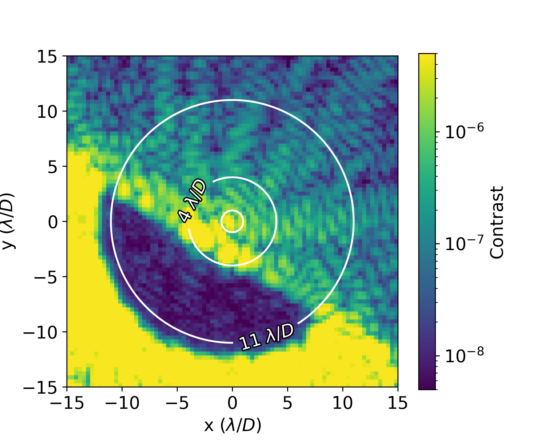 |
The best monochromatic contrast achieved to-date on SCoOB with a knife-edge and Lyot stop is shown in 4, with a mean contrast of from . The current testbed contrast is likely limited by some combination of atmospheric turbulence, mechanical disturbances, laser stability, scattered light, and polarization aberrations. Many upgrades to the system are planned to mitigate these effects, described in the next section.
5 Conclusions and future work
SCoOB is a high contrast imaging testbed at the University of Arizona that has demonstrated a contrast in monochromatic light under unstable laboratory conditions. A number of significant upgrades are underway and slated to be completed by the end of 2022, which will enable the demonstration of broadband dark holes in vacuum under thermal control. These efforts include improvements in the following areas:
Source upgrades: We plan to replace our current laser diode with a supercontinuum fiber laser (the FYLA Iceblink) to demonstrate dark hole digging in 1 to 20% bandpasses with central wavelengths ranging from 450 to 700 nm. A portion of this effort will be directed at reworking the current source optics and spatial filter for a cleaner input beam.
Focal plane masks: We recently integrated a triple-grating charge-6 VVC [3] with our testbed and expect to receive a charge-6 VVC from BEAM Co in the late summer. The majority of our near-future wavefront control efforts will make use of these devices.
Focal plane wavefront control strategies: In addition to our ongoing efforts to refine our I-EFC implementation, an end-to-end Fresnel model has been developed to enable classical EFC on the testbed. Dark hole digging with the SCC will also be demonstrated in the upcoming months.
Low-order wavefront sensors: Plans include testing low-order wavefront sensing approaches including a reflective Lyot stop[19, 20] and a Zernike wavefront sensor[21].
Scattered light: A field stop will be added to a focal plane between the Lyot stop and the science plane to limit scattered light at the science plane[22, 23].
Thermal vacuum chamber: In order to increase stability and eliminate atmospheric effects, we plan to integrate the testbed with a “TVAC” chamber from Rydberg Vacuum Sciences in Fall 2022. We are in the process of acquiring vacuum-compatible cameras, DM cables, and a fine-steering mirror to aid in aligning the PSF to the FPM.
 |
Acknowledgements.
Portions of this work were supported by the Arizona Board of Regents Technology Research Initiative Fund (TRIF). S.H.’s support for this work was provided by NASA through the NASA Hubble Fellowship grant #HST-HF2-51436.001-A awarded by the Space Telescope Science Institute, which is operated by the Association of Universities for Research in Astronomy, Incorporated, under NASA contract NAS5-26555.References
- [1] Maier, E. R., Douglas, E. S., Kim, D. W., Su, K., Ashcraft, J. N., Breckinridge, J. B., Choi, H., Choquet, E., Connors, T. E., Durney, O., Gonzales, K. L., Guthery, C. E., Haughwout, C. A., Heath, J. C., Hyatt, J., Lumbres, J., Males, J. R., Matthews, E. C., Milani, K., Montoya, O. M., N’Diaye, M., Noenickx, J., Pogorelyuk, L., Ruane, G., Schneider, G., Smith, G. A., and Stark, C. C., “Design of the vacuum high contrast imaging testbed for CDEEP, the Coronagraphic Debris and Exoplanet Exploring Pioneer,” in [Space Telescopes and Instrumentation 2020: Optical, Infrared, and Millimeter Wave ], Lystrup, M., Perrin, M. D., Batalha, N., Siegler, N., and Tong, E. C., eds., 11443, 324 – 340, International Society for Optics and Photonics, SPIE (2020).
- [2] Ashcraft, J. N. et al., “The Space Coronagraph Optical Bench (SCoOB): 1. Design and assembly of a vacuum-compatible coronagraph testbed for spaceborne high-contrast imaging technology,” Proc. SPIE 12180, these proceedings (2022).
- [3] Doelman, D. S., Por, E. H., Ruane, G., Escuti, M. J., and Snik, F., “Minimizing the Polarization Leakage of Geometric-phase Coronagraphs with Multiple Grating Pattern Combinations,” Publications of the Astronomical Society of the Pacific 132, 045002 (Mar. 2020). Publisher: IOP Publishing.
- [4] Doelman, D. S. et al., “First laboratory tests of a triple-grating vector vortex coronagraph,” Proc. SPIE 12180, these proceedings (2022).
- [5] Foo, G., Palacios, D. M., and Swartzlander, G. A., “Optical vortex coronagraph,” Opt. Lett. 30, 3308–3310 (Dec 2005).
- [6] Mawet, D., Murakami, N., Delacroix, C., Serabyn, E., Absil, O., Baba, N., Baudrand, J., Boccaletti, A., Burruss, R., Chipman, R. A., Forsberg, P., Habraken, S., Hamaguchi, S., Hanot, C., Ise, A., Karlsson, M., Kern, B., Krist, J., Kuhnert, A., Levine, M., Liewer, K., McClain, S. C., McEldowney, S., Mennesson, B., Moody, D., Murakami, H., Niessner, A., Nishikawa, J., O’Brien, N. A., Oka, K., Park, P., Piron, P., Pueyo, L., Riaud, P., Sakamoto, M., Tamura, M., Trauger, J. T., Shemo, D. M., Surdej, J., Tabirian, N., Traub, W. A., Wallace, J. K., and Yokochi, K., “Taking the vector vortex coronagraph to the next level for ground- and space-based exoplanet imaging instruments: review of technology developments in the USA, Japan, and Europe,” Techniques and Instrumentation for Detection of Exoplanets V 8151, 815108 (Sept. 2011). Publisher: SPIE.
- [7] Galicher, R. and Baudoz, P., “Expected performance of a self-coherent camera,” Comptes Rendus Physique 8(3), 333–339 (2007).
- [8] Derby, K. et al., “Tolerance analysis of a self-coherent camera for wavefront sensing and dark hole maintenance,” Proc. SPIE 12180, these proceedings (2022).
- [9] Guyon, O., Sevin, A., Gratadour, D., Bernard, J., Ltaief, H., Sukkari, D., Cetre, S., Skaf, N., Lozi, J., Martinache, F., Clergeon, C., Norris, B., Wong, A., and Males, J., “The compute and control for adaptive optics (CACAO) real-time control software package,” in [Adaptive Optics Systems VI ], Close, L. M., Schreiber, L., and Schmidt, D., eds., Society of Photo-Optical Instrumentation Engineers (SPIE) Conference Series 10703, 107031E (July 2018).
- [10] Males, J. R., Close, L. M., Miller, K., Schatz, L., Doelman, D., Lumbres, J., Snik, F., Rodack, A., Knight, J., Van Gorkom, K., Long, J. D., Hedglen, A., Kautz, M., Jovanovic, N., Morzinski, K., Guyon, O., Douglas, E., Follette, K. B., Lozi, J., Bohlman, C., Durney, O., Gasho, V., Hinz, P., Ireland, M., Jean, M., Keller, C., Kenworthy, M., Mazin, B., Noenickx, J., Alfred, D., Perez, K., Sanchez, A., Sauve, C., Weinberger, A., and Conrad, A., “MagAO-X: project status and first laboratory results,” in [Adaptive Optics Systems VI ], Close, L. M., Schreiber, L., and Schmidt, D., eds., Society of Photo-Optical Instrumentation Engineers (SPIE) Conference Series 10703, 1070309 (July 2018).
- [11] Ruane, G., Echeverri, D., Bendek, E., Kern, B. D., Marx, D., Mawet, D., Prada, C. M., Riggs, A. J. E., Seo, B.-J., Serabyn, E., and Shaklan, S., “Microelectromechanical deformable mirror development for high-contrast imaging, part 2: the impact of quantization errors on coronagraph image contrast,” Journal of Astronomical Telescopes, Instruments, and Systems 6 (Oct. 2020). arXiv: 2010.03704.
- [12] Thurman, S. T., DeRosa, R. T., and Fienup, J. R., “Amplitude metrics for field retrieval with hard-edged and uniformly illuminated apertures,” Journal of the Optical Society of America A 26, 700 (Mar. 2009).
- [13] Van Gorkom, K., Males, J. R., Close, L. M., Lumbres, J., Hedglen, A., Long, J. D., Haffert, S. Y., Guyon, O., Kautz, M., Schatz, L., Miller, K., Rodack, A. T., Knight, J. M., and Morzinski, K. M., “Characterizing deformable mirrors for the MagAO-X instrument,” Journal of Astronomical Telescopes, Instruments, and Systems 7, 039001 (July 2021).
- [14] Kasper, M., Fedrigo, E., Looze, D. P., Bonnet, H., Ivanescu, L., and Oberti, S., “Fast calibration of high-order adaptive optics systems,” Journal of the Optical Society of America A 21, 1004 (June 2004).
- [15] Dean, B. H. and Bowers, C. W., “Diversity selection for phase-diverse phase retrieval,” Journal of the Optical Society of America A 20, 1490 (Aug. 2003).
- [16] Haffert, S. Y., Males, J., Van Gorkom, K., Close, L., Long, J., Hedglen, A., Guyon, O., Schatz, L., Kautz, M., Rodack, A., Knight, J., Sun, H., and Forgarty, K., “Advanced wavefront sensing and control demonstration with MagAO-X,” in [Adaptive Optics Systems VIII ], 12185, SPIE (2022).
- [17] Haffert, S. et al. (in prep).
- [18] Give’on, A., Kern, B., Shaklan, S., Moody, D. C., and Pueyo, L., “Broadband wavefront correction algorithm for high-contrast imaging systems,” 66910A (Sept. 2007).
- [19] Singh, G., Martinache, F., Baudoz, P., Guyon, O., Matsuo, T., Jovanovic, N., and Clergeon, C., “Lyot-based Low Order Wavefront Sensor for Phase-mask Coronagraphs: Principle, Simulations and Laboratory Experiments,” Publications of the Astronomical Society of the Pacific 126, 586 (June 2014). Publisher: IOP Publishing.
- [20] Mendillo, C. B., Brown, J., Martel, J., Howe, G. A., Hewawasam, K., Finn, S. C., Cook, T. A., Chakrabarti, S., Douglas, E. S., Mawet, D., Guyon, O., Singh, G., Lozi, J., Cahoy, K. L., and Marinan, A. D., “The low-order wavefront sensor for the PICTURE-C mission,” in [Techniques and Instrumentation for Detection of Exoplanets VII ], 9605, 423–434, SPIE (Sept. 2015).
- [21] N’Diaye, M., Vigan, A., Dohlen, K., Sauvage, J.-F., Caillat, A., Costille, A., Girard, J. H. V., Beuzit, J.-L., Fusco, T., Blanchard, P., Le Merrer, J., Le Mignant, D., Madec, F., Moreaux, G., Mouillet, D., Puget, P., and Zins, G., “Calibration of quasi-static aberrations in exoplanet direct-imaging instruments with a Zernike phase-mask sensor: II. Concept validation with ZELDA on VLT/SPHERE,” Astronomy & Astrophysics 592, A79 (Aug. 2016).
- [22] Llop-Sayson, J., Jovanovic, N., Morrissey, G., Echeverri, D., and Mawet, D., “Wavefront control experiments with a single mode fiber at the High-Contrast Spectroscopy Testbed for Segmented Telescopes (HCST),” in [Society of Photo-Optical Instrumentation Engineers (SPIE) Conference Series ], Society of Photo-Optical Instrumentation Engineers (SPIE) Conference Series 11443, 114432Q (Dec. 2020).
- [23] Desai, N., Llop-Sayson, J., Jovanovic, N., Ruane, G., Serabyn, E., Martin, S., and Mawet, D., “High contrast demonstrations of novel scalar vortex coronagraph designs at the high contrast spectroscopy testbed,” in [Techniques and Instrumentation for Detection of Exoplanets X ], 11823, 238–246, SPIE (Sept. 2021).