Electron subband degeneracy heat pump for cryogenic cooling
Abstract
An unconventional method of continuous solid-state cryogenic cooling utilizing the electron subband degeneracy of semiconductor heterostructures is proposed in this Letter. An electrostatic heat pump is modeled, which employs subband “expansion” and “compression” to reach sub-dilution refrigeration temperatures with the fundamental limit set by electron-phonon interaction. Using an ultra-wide GaAs quantum well as an example, the cooling power per unit volume is estimated to reach with a hot-side temperature of mK, suitable for applications such as quantum computers or infrared detectors.
I Introduction
Sustainable and efficient millikelvin cryogenic cooling is essential for supporting cutting-edge applications such as solid-state quantum computation as well as other low-temperature experiments that require low temperatures such as infrared detectorsGardner et al. (2006); Agnese et al. (2014) or quantum states with long coherence times such as the quantum Hall effectLevitin et al. (2022). To achieve millikelvin temperatures, one of the most common technologies is the \ce^3He/\ce^4He dilution refrigeratorDas, Ouboter, and Taconis (1965). However, since \ce^3He is a scarce and non-renewable resource, alternative approaches for achieving millikelvin temperatures are greatly desired. Demagnetization refrigeration using polarizable salts only partly solves the problem, since it requires an ancillary multi-Tesla superconducting electromagnet with accompanying power-supply, cryogenic system, and troublesome stray fieldsFigueroa-Feliciano et al. (2015); Adams et al. (2020). Furthermore, the indirect nature of electron cooling via these phononic refrigeration mechanisms suffers from the notoriously weak coupling of electrons to cooled phonons. A large Kapitza-like thermal resistancePollack (1969) develops between electron and phonon baths due to the vanishing electron-phonon coupling at lower temperatures, meaning that the base temperature of the electron system is frequently much higher than that of the nominal dilution refrigerator base temperature.
In this Letter, a novel approach for sustained cooling is proposed that utilizes electrons, themselves, directly as the regfrigeration mediumGrayson (2022). Just as a dilution refrigerator expands the phase-space of \ce^3He in the \ce^3He/\ce^4He mixture from a low entropy-per-particle state (the concentrated phase) to a high-entropy-per-particle state (the dilute phase) to achieve cooling, this work proposes a novel solid state heat pump that will expand the phase space of a two-dimensional electron system (2DES) from one to multiple subbands to generate cooling power. As a direct means of cooling electrons, this compact mechanism could realize low electron temperatures competitive with standard but cumbersome cryogenic methods. Under this proposal, the weak coupling of phonons and electrons at extreme low temperature becomes an advantage, as it eliminates one possible source of heat leak to the cold electrons from hot phonons. Realizing a solid-state active cooling mechanism at the coldest end of the temperature spectrum will reduce the volume of solid-state cryocoolers by orders of magnitude, increase hold times and improve thermal stability allowing active compensation of heat leaks. The parasitic heat losses for the proposed solid-state refrigerator decrease rapidly at lower temperatures, so this refrigeration method has no fundamental low-temperature limit. Since coherence times typically increase with decreasing temperatureDuan and Guo (1998), this may help to extend quantum coherence for solid-state quantum information storage.
II Device Design
The solid state heat pump is based on a semiconductor heterostructure with tunable quantum well subband occupancy. This is achieved via metal gates on both front and back surfaces. Rego and KirczenowRego and Kirczenow (1999) first theoretically proposed that under single-shot operation of front and back gate biasing, the electron subband degeneracy of the 2DES can be increased without changing the electron density, and as such, the temperature is adiabatically decreased by the same degeneracy factor ratio. However, in their proposed single-shot operation no heat is removed from the 2DES and the drop in temperature is rapidly recovered through contact with the phonon heat bath. The present work extends beyond this proposal, where here a cyclic heat pump operating according to the thermodynamic Otto cycle of a heat engine, achieves sustained cryogenic cooling power. Whereas a standard heat pump uses a working medium of molecular gas or liquid manipulated by mechanical pistons and thermal switches, in this Letter, a working medium of electrons in a quantum well is manipulated by electrostatic gates and electron heat-switch gates. The cyclic disconnecting of electrical conduction via capacitive heat-switches allows the Wiedemann-Franz law to be side-stepped, since there never exists a continuous path of electrical conduction from the cold load across the central 2DES to the heat bath.
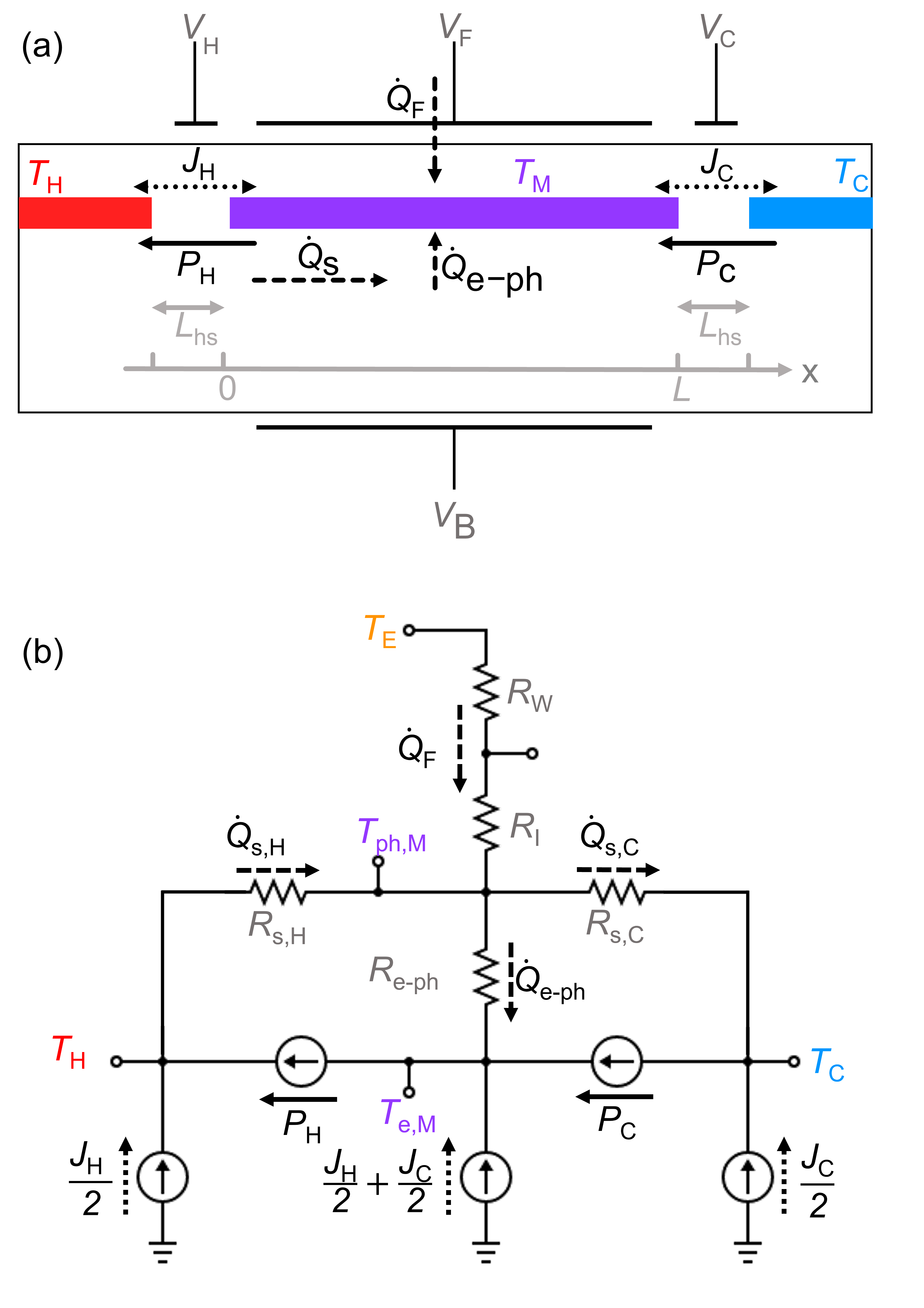
Figure 1a shows a schematic of the proposed device. The electrons that function as the working medium for refrigeration are in the central region (purple) of the quantum well at variable temperature . The front and back gates are biased to voltages and , which are referred to as the piston gates for compression and expansion analogous to the mechanical heat pump. As such, the piston gates serve to cyclically compress the electrons to low subband degeneracy or to expand the electrons to high subband degeneracy . The heat switch gates biased with voltages and can electrostatically deplete the electrons that connect the working medium to the hot and cold sides, respectively, so that direct electronic conduction of heat across the entire device is inhibited throughout the refrigeration cycle. The various heat flows in Fig. 1a are indicated with arrows, indicating the predominant direction of heat flow under proper operation, where the solid black arrows indicate cooling power, dashed arrows represent Fourier heat flow from high to low temperature, and dotted arrows represent Joule heating from the depletion and repopulation of the 2DEG under the heat-switch gates. The thermal equivalent “circuit” is drawn in Fig. 1b to aid in analysis, where temperatures are represented as “voltages”, heat flow as “current”, and thermal resistance as electrical “resistors”. Wires that connect to the gate terminals as well as the gate metals themselves will be made of superconductor, such as aluminum, whose electronic thermal conductivity is negligible, eliminating the heat leak through those electrical contactsBardeen, Rickayzen, and Tewordt (1959); Satterthwaite (1962). Normal metal wires, such as gold, will connect the hot side of the device to the external heat sink and the cold side to the load to-be-cooled to achieve good thermal contact to those respective electron baths..
III Working Principle
The cooling power is generated by operating the working medium of electrons in an Otto cycleWu (2003). Figure 2 shows this - diagram, which is comprised of adiabatic expansion, isochoric heating, adiabatic compression, and isochoric cooling. Here the isochoric legs represent constant subband degeneracy . The two curves for degenerate electron systems with different subband degeneracy, , can be obtained via Sommerfeld expansionAshcroft and Mermin (1976) and are plotted in blue solid lines in Fig. 2,
| (1) |
where , , , , and represent the electron subband degeneracy factor, effective mass, Boltzmann constant, quantum well area, and electron working medium temperature, respectively. The parameter in the right-hand equation is defined, , which is material-dependent only through the electron effective mass and geometry dependent only through the device area .
The four legs of the Otto cycle can be described as follows, with the inset reproductions of Fig. 1 in miniature illustrating the heat switch positions for each case. (A) Both heat switches are disconnected. The temperature of the working medium drops from to via an adiabatic expansion by biasing the front and back piston gates. (B) The heat switch shown on the right is connected, coupling the working medium to the cold load at , and heat is drawn away from the cold load to the working medium as the working medium undergoes isochoric heating. (C) Adiabatic compression is achieved by biasing the piston gates appropriately with both heat switches disconnected, and the temperature of the working medium is increased from to . (D) Finally, the working medium undergoes isochoric cooling from to , ejecting heat to the heat sink through the heat switch on the left.
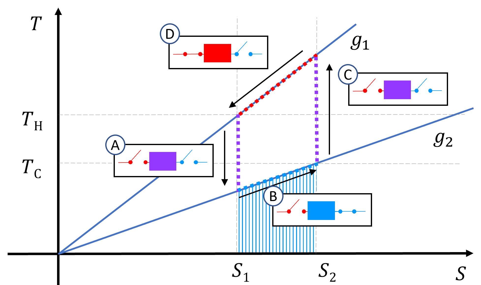
In the Otto cycle calculation below, we determine that MHz to GHz cycle frequencies can supply sufficient cooling power to compensate for parasitic heat loads, with excess cooling power to operate as a refrigerator. This refrigeration power can be used, for example, to overcome heat leaks from multiple electrical leads attached to a device targeted for refrigeration or from incident infrared radiation entering a detector window. For a given operating frequency and heat sink temperature , the cooling power can be calculated from the shaded region of the - diagram of Fig. 2,
| (2) |
The primary source of electron heating in the device that will counteract this cooling power is direct electron-phonon coupling in the quantum well. It has been shown theoreticallyPrice (1982) and experimentally Mittal et al. (1996) that the local heat exchange from phonons at to electrons at follows a power law,
| (3) |
where is the quantum well electron density. The position-dependent phonon temperature is , where measures the length from the hot side at to the cold side at shown in gray at the bottom of Fig. 1a. On the other hand, the electrons are expected to have much faster thermal diffusion times than the phonons and are therefore modeled as having uniform temperature across the width of the quantum well. The heat flow density through the lattice is is approximated as being time independent under steady-state operation of the refrigerator. The thermal conductivity of the lattice follows a power law, . Integrating both sides of this steady-state heat flow expression across the length of the device from to results in the following expression for the phonon temperature as a function of position for a fixed heat sink temperature,
| (4) |
The local phonon temperature described in Eq. 4 will create a phonon backflow of heat from hot to cold reservoirs. The heat flow through the substrate phonons due to the temperature gradient is modeled as a one-dimensional heat flow described by the integral of the phonon thermal conductivity across the length of the sample, where and are the temperature-independent phonon sound velocity and mean free path, respectively, and is the phonon specific heat. For the total heat flow, this gives
| (5) |
where , , are the sample width, substrate thickness, and heat switch gate length, respectively. Calculations assume an experimentally reasonable thinned substrate which can be achieved by mechanically or chemically thinning the sample, and even thinner micron-scale substrates can be achieved with remote epitaxial growwthKim et al. (2017), thereby reducing the cross-sectional area for the substrate phonon back-flow.
The only source of Joule heating comes from electrons depleting and repopulating the heat-switch gates, which can be reduced by including an oppositely biased reservoir gate immediately next to the heat-switch gate of equal dimensions whose accumulated charge can accommodate the depleted charge under the heat switch. With such a design, Joule heating is given by
| (6) |
where , , , , and are the length of the heat switch gates, operating frequency, the quantum well electron density, electron mobility, and electron charge, respectively.
The upper bound for the frequency of operation will be set by the time timescale associated with the diffusion of the electronic heat along the QW length to achieve thermal equilibration of the central QW electrons with the cold load or the heat sink, respectively. This timescale is given by , implying a frequency-dependent thermal diffusion length:
| (7) |
with electron thermal diffusivity constant , whereby the thermal diffusion frequency is , since the thermal equilibration has to occur twice per cycle – once for cold-load equilibration, and once for heat-sink equilibration. The diffusion length represents an upper bound for a device operating with given frequency , thus choosing provides maximum cooling power. By adjusting the width in order to hold the total device area of the central heat-pump region constant, we can simplify the geometry to , which gives the optimal geometry for a device operating at any given frequency.
IV Material and Device Parameters
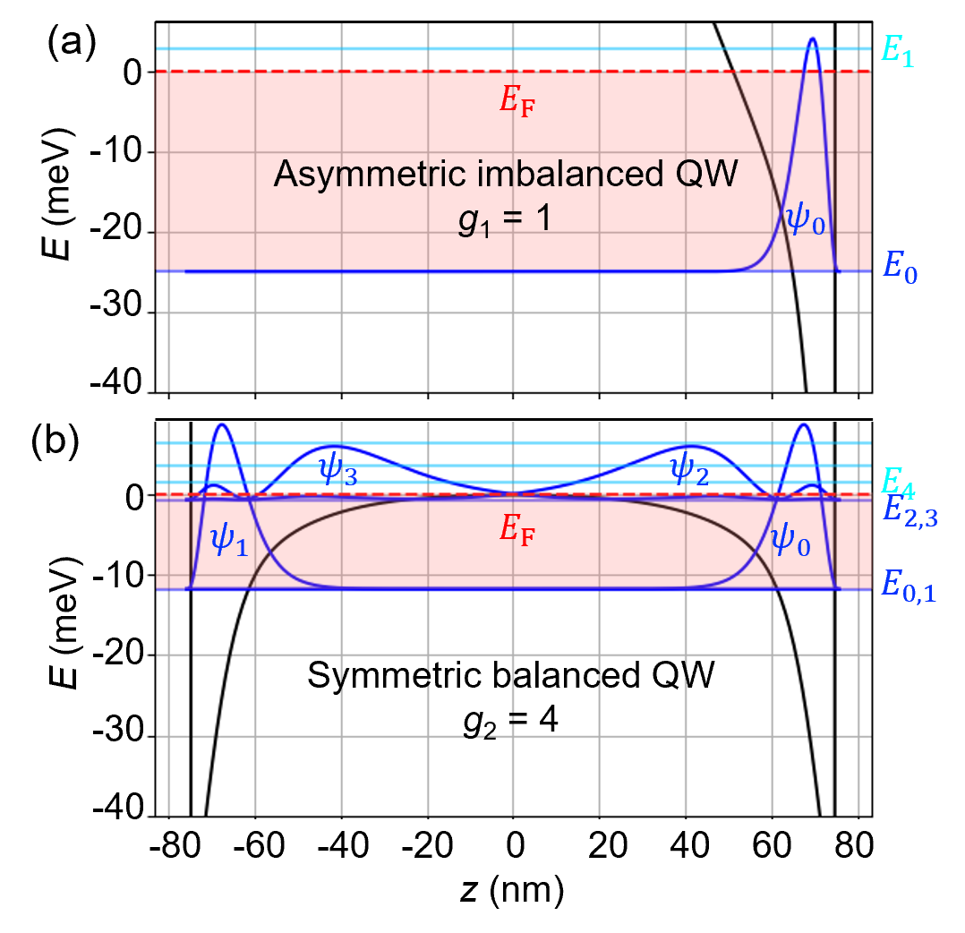
We calculate the viability of net cryogenic cooling power using a GaAs quantum well as an example. An ultra-wide quantum well-width nm is chosen to maximize the ratio of degeneracy factors and . Figure 3 shows a self-consistent Hartree calculation of quantum well subband energiesHebal et al. (2021). When imbalanced with a large positive voltage on the front- and large negative voltage on the back-piston gates, a sharp triangular quantum well is formed at the front interface, shown in Fig. 3a. A density of electrons in this GaAs quantum well with an effective mass of will populate only the lowest subband, with energy in the Hartree calculations of Fig. 3a. Note that the next nearest subband lies above the Fermi energy and is therefore unpopulated. When this same density is balanced by compensating front- and back-piston gate voltages to a square-well configuration for the bare potential, the Coulomb repulsion of the electrons results in two symmetric triangular wells at the opposite corners of the well, Fig. 3b. These electrons together populate four subbands: the ground states , and the first excited states , in the right and left triangular wells, respectively. Thus, the same density of electrons in this wide quantum well can therefore be tuned from to subband degeneracy.
V Cooling Power
With the above model, the cooling power of the Otto cycle refrigerator can be estimated, as well as the net cooling power considering the heat loss terms defined earlier in the Letter,
| (8) |
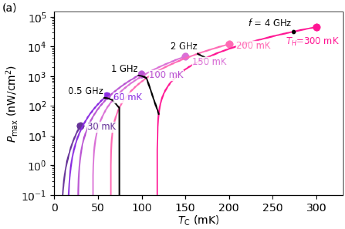
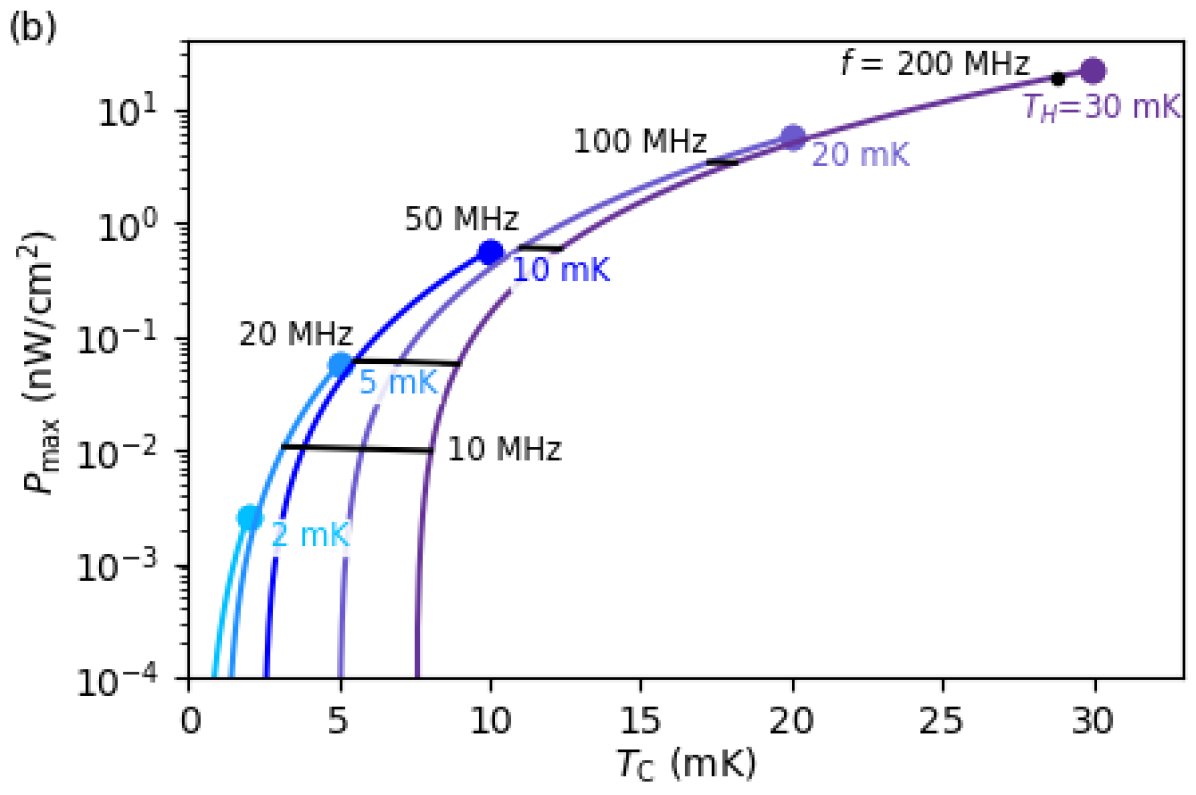
For a range of heat sink temperatures to , Fig. 4 shows the calculated maximum net cooling power at optimal device length from Eq. 7 and frequency at each for a subband degeneracy refrigerator with : = 4:1 and µm heat switch gates. Simulations assume a quantum well with electron density , electron mobility Reichl et al. (2014); Banerjee et al. (2018); Hwang and Sarma (2008); Manfra (2014) known to be achievable below Schlom and Pfeiffer (2010), and GaAs electron effective mass . Substrate parameters are thickness µm, phonon velocity , and phonon mean-free path µm Fon et al. (2002). The calculations in Fig. 4a shows that this simple, single stage cooler can yield up to µW of net cooling power per of device area at and consistently supply several microwatts per of cooling with . In Fig. 4b, we see such a device can provide tens of nanowatts of cooling per with as low as . Volumetric cooling could be realized by vertically stacking 100 devices, each of thickness µm thick, electrically connected in parallel, allowing one to consider a volumetric cooling power per unit device volume. Multiplying the power per unit area in Fig. 4 by = 100/cm yields such a volumetric cooling power per unit volume. These calculations suggest we can achieve of volumetric cooling power density at hot side .
VI Discussion
The solid-state refrigeration described here would initially serve to enhance cooling power near base temperature in tandem with a dilution refrigerator. To eventually compete with dilution refrigeration, cascaded multistage designs must be considered to allow for higher hot-side temperatures while achieving greater thermal differentials to colder base temperatures. The lateral design of the subband degeneracy refrigerator could be particularly well-suited for cascading, allowing for simple, monolithic, planar cascade designs where the heat sink of the former stage serves as the cold load of the latter stage.
Alternatively, the subband degeneracy refrigerator could be paired with other solid state cooling mechanisms such as superconducting-insulating-normal metal junction cooling to achieve a composite cascaded solid-state alternative to dilution refrigerationLeivo, Pekola, and Averin (1996); O’Neil et al. (2012). Other thermodynamic heat pump cycles besides the Otto cycle may lead to improved cooling efficiency or increased cooling power at higher temperatures where electron-phonon coupling is enhanced. This proposed device therefore represents an initial candidate low-temperature stage for future exploration of solid-state refrigeration.
Acknowledgements.
This material is based upon work supported by the U.S. Department of Energy, Office of Science, National Quantum Information Science Research Centers, Superconducting Quantum Materials and Systems Center (SQMS) under the contract No. DE-AC02-07CH11359. T.D. thanks the support of URAP funding from the Office of Undergraduate Research, Northwestern University. The authors also thank Lucia Steinke (U. Florida) for insightful conversations.References
- Gardner et al. (2006) J. P. Gardner, J. C. Mather, M. Clampin, R. Doyon, M. A. Greenhouse, H. B. Hammel, J. B. Hutchings, P. Jakobsen, S. J. Lilly, K. S. Long, et al., “The james webb space telescope,” Space Science Reviews 123, 485–606 (2006).
- Agnese et al. (2014) R. Agnese, A. J. Anderson, M. Asai, D. Balakishiyeva, R. B. Thakur, D. Bauer, J. Beaty, J. Billard, A. Borgland, M. Bowles, et al., “Search for low-mass weakly interacting massive particles with supercdms,” Physical review letters 112, 241302 (2014).
- Levitin et al. (2022) L. V. Levitin, H. van der Vliet, T. Theisen, S. Dimitriadis, M. Lucas, A. D. Corcoles, J. Nyéki, A. J. Casey, G. Creeth, I. Farrer, et al., “Cooling low-dimensional electron systems into the microkelvin regime,” Nature communications 13, 1–8 (2022).
- Das, Ouboter, and Taconis (1965) P. Das, R. Ouboter, and K. Taconis, “A realization of a london-clarke-mendoza type refrigerator,” in Low Temperature Physics LT9 (Springer, 1965) pp. 1253–1255.
- Figueroa-Feliciano et al. (2015) E. Figueroa-Feliciano, A. J. Anderson, D. Castro, D. C. Goldfinger, J. Rutherford, M. E. Eckart, R. L. Kelley, C. A. Kilbourne, D. McCammon, K. Morgan, et al., “Searching for kev sterile neutrino dark matter with x-ray microcalorimeter sounding rockets,” The Astrophysical Journal 814, 82 (2015).
- Adams et al. (2020) J. Adams, R. Baker, S. Bandler, N. Bastidon, M. Danowski, W. Doriese, M. Eckart, E. Figueroa-Feliciano, D. Goldfinger, S. Heine, et al., “First operation of tes microcalorimeters in space with the micro-x sounding rocket,” Journal of Low Temperature Physics 199, 1062–1071 (2020).
- Pollack (1969) G. L. Pollack, “Kapitza resistance,” Reviews of modern physics 41, 48 (1969).
- Grayson (2022) M. Grayson, “Cryogenic solid state heat pump,” International Patent PCT/US2020/03 1082 (2022).
- Duan and Guo (1998) L.-M. Duan and G.-C. Guo, “Reducing decoherence in quantum-computer memory with all quantum bits coupling to the same environment,” Physical Review A 57, 737 (1998).
- Rego and Kirczenow (1999) L. G. Rego and G. Kirczenow, “Electrostatic mechanism for cooling semiconductor heterostructures,” Applied physics letters 75, 2262–2264 (1999).
- Bardeen, Rickayzen, and Tewordt (1959) J. Bardeen, G. Rickayzen, and L. Tewordt, “Theory of the thermal conductivity of superconductors,” Physical Review 113, 982 (1959).
- Satterthwaite (1962) C. Satterthwaite, “Thermal conductivity of normal and superconducting aluminum,” Physical Review 125, 873 (1962).
- Wu (2003) C. Wu, Thermodynamic cycles: computer-aided design and optimization (CRC Press, 2003).
- Ashcroft and Mermin (1976) N. Ashcroft and N. Mermin, Solid State Physics (Saunders College, Philadelphia, 1976).
- Price (1982) P. J. Price, “Hot electrons in a gaas heterolayer at low temperature,” Journal of Applied Physics 53, 6863–6866 (1982).
- Mittal et al. (1996) A. Mittal, R. Wheeler, M. Keller, D. Prober, and R. Sacks, “Electron-phonon scattering rates in gaas/algaas 2deg samples below 0.5 k,” Surface Science 361-362, 537–541 (1996).
- Kim et al. (2017) Y. Kim, S. S. Cruz, K. Lee, B. O. Alawode, C. Choi, Y. Song, J. M. Johnson, C. Heidelberger, W. Kong, S. Choi, et al., “Remote epitaxy through graphene enables two-dimensional material-based layer transfer,” Nature 544, 340–343 (2017).
- Hebal et al. (2021) H. Hebal, Z. Koziol, S. Lisesivdin, and R. Steed, “General-purpose open-source 1d self-consistent schrödinger-poisson solver: Aestimo 1d,” Computational Materials Science 186, 110015 (2021).
- Reichl et al. (2014) C. Reichl, J. Chen, S. Baer, C. Rössler, T. Ihn, K. Ensslin, W. Dietsche, and W. Wegscheider, “Increasing the = 5/2 gap energy: an analysis of mbe growth parameters,” New Journal of Physics 16, 023014 (2014).
- Banerjee et al. (2018) M. Banerjee, M. Heiblum, V. Umansky, D. E. Feldman, Y. Oreg, and A. Stern, “Observation of half-integer thermal hall conductance,” Nature 559, 205–210 (2018).
- Hwang and Sarma (2008) E. Hwang and S. D. Sarma, “Limit to two-dimensional mobility in modulation-doped gaas quantum structures: How to achieve a mobility of 100 million,” Physical Review B 77, 235437 (2008).
- Manfra (2014) M. J. Manfra, “Molecular beam epitaxy of ultra-high-quality algaas/gaas heterostructures: enabling physics in low-dimensional electronic systems,” Annu. Rev. Condens. Matter Phys. 5, 347–373 (2014).
- Schlom and Pfeiffer (2010) D. G. Schlom and L. N. Pfeiffer, “Upward mobility rocks!” Nature materials 9, 881–883 (2010).
- Fon et al. (2002) W. Fon, K. Schwab, J. Worlock, and M. Roukes, “Phonon scattering mechanisms in suspended nanostructures from 4 to 40 k,” Physical review B 66, 045302 (2002).
- Leivo, Pekola, and Averin (1996) M. Leivo, J. Pekola, and D. Averin, “Efficient peltier refrigeration by a pair of normal metal/insulator/superconductor junctions,” Applied physics letters 68, 1996–1998 (1996).
- O’Neil et al. (2012) G. C. O’Neil, P. J. Lowell, J. M. Underwood, and J. N. Ullom, “Measurement and modeling of a large-area normal-metal/insulator/superconductor refrigerator with improved cooling,” Physical Review B 85, 134504 (2012).