Supplementary Materials: Translating Visual LEGO Manuals to a Machine-Executable Plan
First, we introduce our data generation pipeline for LEGO synthetic dataset in Section 1 and 3D-Craft in Section 2. Then we provide more implementation details and hyperparameters of models in Section 3. Section 4 explains some details of the 3D Pose Inference stage of MEPNet. Section 5 explains some details of camera parameter estimation of our datasets. Section 6 presents some additional ablation studies. Section 7 discusses the limitations of our paper. Section 8 lists the attribution and license for assets used in this paper. Finally, we provide some step-by-step building visualization of our model in Section 9.
1 Synthetic Dataset Generation
We generate the synthetic dataset in two stages: the first stage (the “forward” stage) randomly builds a complete LEGO shape, and the second stage (the “backward” stage) decomposes the final shape into multiple synthetic manual assembly steps.
1.0.1 Forward Stage
In the forward stage, we first sample the length, width and maximum height of the bounding box of the final shape. Next, we repeat the following process iteratively.
At each iteration, we randomly partition the bounding box into smaller boxes, and apply one of the following operations to each box:
-
1.
Randomly fill the box with as many arbitrary components as possible.
-
2.
Sample edges from the box, “grow” the height of the edges by adding random components. Afterwards, fill the non-edge area within the region with random components.
To add components, each time we randomly sample a position first, and then use one of the three strategies: 1. randomly select a primitive brick and add it at the sampled position ; 2. build a submodule by randomly stacking multiple bricks within a small 3D bounding box and add it at the sampled position; 3. randomly select a primitive brick and stack multiple instances together and add them at the sampled position. We use rejection sampling to ensure each component will be connected to at least one of the other components and there is no collision between components.
1.0.2 Backward Stage
The backward stage constructs the manual iteratively. Starting from the fully built shape, at each iteration, we identify all the components that are removable from the current base shape, and compute the percentage of pixels of the components that are visible from a top-down view and a side view. If the visibility percentage is larger than a threshold, we mark the component as visible. We group the components that are removable and visible into multiple chunks, such that each chunk has at most 10 components instances and at most 5 component types. Each chunk will correspond to a step in the manual. Then we remove one chunk at a time and render the resulting shape as a manual image using predefined camera parameters. We perform this operation until all the components have been removed and obtain a series of manual images that illustrate the whole assembly process of the given object.
2 3D-Craft Dataset Generation
Different from the data generation pipeline of the synthetic LEGO dataset, where we randomly select components to be in a step in the backward stage, the houses in the 3D-Craft dataset already come with a construction order made by humans. To maintain this order information, we start from an empty world, and add only one brick at a time according to the human construction sequence. To make sure that the manual image contains information about the added brick in each step, we iterate over a predefined set of viewpoints and select the viewpoint where the brick is visible. If there is no valid viewpoint we just randomly select one from a predefined set. Next, we render the scene with the selected viewpoint and use the result as the manual for this step.
3 Implementation Details
3.1 Symmetry-aware rotation prediction.
In the LEGO bricks we considered, every brick may have rotation symmetry of order , , or . That is, the brick remains unchanged when being rotated for degrees. For each brick, our model predicts the component’s rotation as well as the rotation symmetry class it belongs to. This is achieved by a 7-way classification where the prediction is interpreted as:
-
•
: The brick has rotation symmetry of order 4.
-
•
: The brick has rotation symmetry of order 2 and its rotation is .
-
•
: The brick has rotation symmetry of order 2 and its rotation is .
-
•
: The brick has no rotation symmetry and its rotation is .
3.1.1 Baseline models on LEGO datasets.
As baseline models directly predict 3D translations for each component as a continuous parameter, we implement a post-processing algorithm to refine the predictions by utilizing connection constraints in LEGOs. First, we round each entry of the predicted 3D translation to the nearest . Then we search the translation that satisfies connection constraints in a small neighborhood of the rounded 3D translation. More specifically, the component must be connected to another component and there is no collision between components. Suppose the rounded translation is , the neighborhood is defined as
We select the valid translation from the neighborhood that is closest to the original rounded prediction. If none of the translations is valid, we use as the final prediction.
3.1.2 3D-Craft dataset.
In the 3D-Craft dataset, a brick can either be put on the ground or attached to a neighboring brick. Therefore, given the base shape of the house, we can compute all 3D valid positions for the new brick. We project them onto the image plane, and perform a matching with the detected keypoint of the new brick. The keypoint of a brick is set to be its center/origin. The predicted 3D translation is set to be the valid position whose 2D projection is closest to the detected keypoint. For baseline models, we use a similar post-processing algorithm as the algorithm for LEGO datasets based on a local search.
3.1.3 Hyperparameters
The size of the voxel grid for the base shape is set to be , and the size of the voxel grid for each component is set to be . For the training losses:
We set and to and to . For Direct3D, and are replaced with whose weight is also set to 1. All models except VoxelCNN are trained with the AdamW [3] optimizer. VoxelCNN is trained with SGD, following the implementation of the original paper. Other hyperparameters can be found in Table 1.
| Dataset | Learning Rate | Batch Size | Epochs | |
| LEGO | MEPNet | |||
| Direct3D | ||||
| PartAssembly | ||||
| 3D-Craft | MEPNet | |||
| Direct3D | ||||
| VoxelCNN |
4 Details of 3D Pose Inference.
4.0.1 Inferring 2D locations of anti-studs of the new component.
Here, we show that under scaled orthographic projection, the 2D offset on the image plane between a component’s keypoint and its anti-studs can be computed without knowing the actual “depth” (which is unknown) of the component. This enable us to compute the 2D positions of anti-studs on the manual image only based on 2D keypoint information.
Recall that in scaled orthographic projection, the 2D projection of a point can be computed by
where is the scale factor and correspond to the extrinsic parameters of the camera (rotation and translation, respectively). Denote . For any two points in the world homogeneous coordinates, their offset on 2D image plane coordinate system can be computed as .
Therefore, if we consider two points on a component (e.g., the detected keypoint and an anti-stud of the brick), their relative position on the 2D image plane can be computed independent of the placement of this component. Thus, given a detected keypoint on the 2D image plane, we can directly computes the position of all anti-studs of the component (on 2D), and match them with the studs on the base shape.
4.0.2 Empty base shape
At the beginning of assembly, rather than connecting to another component, a component can also be put directly on ground. For this special case, given the 2D keypoint and rotation of a detected component, we will directly search over all possible translations and select the one whose keypoint position is closest to the detected keypoint.
4.0.3 Handling submodules with multiple topmost primitive bricks.
To predict the 3D translation of a submodule, the pose estimation module is expected to detect its 2D keypoint, which is the 2D keypoint of the topmost primitive brick in this submodule. However, the identity of the topmost primitive can be ambiguous when there are multiple components at the same “top” layer. To handle this, we extend the rotation inference by synthesis algorithm. For each submodule, we perform a joint search of the 3D rotation and the topmost brick that our model detects. Assuming there are topmost bricks for the target submodule, this results in at most unique candidate 3D poses. Next, following the basic rotation inference by synthesis algorithm, we use a camera projection subroutine to compute the mask of the component with each candidate pose, and select the pose that has the highest IoU with the predicted mask.
5 Camera Parameters
5.0.1 Camera parameters of the LEGO datasets.
The camera parameters in training and test sets are chosen from real LEGO manuals. Specifically, we have selected a small set of LEGO manuals, together with their corresponding target 3D shapes. Next, we use SoftRasterizer [1] to find the camera parameters that maximize the IoU between the projected 3D shapes and the shape masks segmented from the real LEGO manuals. We select a common set of camera parameters to render the Classics and Architecture datasets. For the synthetic dataset, the camera parameters have scales sampled from , translations sampled from in the NDC space, and rotations sampled from . This covers the camera parameter distribution of the real LEGO manuals we consider.
5.0.2 Camera parameter estimation.
Our model can be integrated with external camera parameter estimation algorithms. Specifically, we use the model from Xiao et al. [6] that receives a 3D shape and target image as inputs and predicts their camera parameters. Since the original model only predicts orientation of the camera given a target image and 3D object, we add scale and translation prediction modules using multi-layer perceptrons. The model is supervised by a mean squared error loss. We train the model using camera parameters from the synthetic datasets. Using the predicted camera parameters, MEPNet can achieve the same pose accuracy and Chamfer distance metrics as using the groundtruth camera parameters acorss all three LEGO datasets.
6 Additional Results
| Pose Acc (%) | CD | |
| MEPNet (GT Trans.) | 96.38 | 32.92 |
| MEPNet (GT Rot.) |
6.0.1 Ablation of the Hourglass architecture.
To validate the effectiveness of the Hourglass architecture, we use another encoder-decoder model built from ResNet and deconvolutional layers [5] to build an ablation model. We replace the Hourglass architecture in MEPNet with this ablation model and evaluate it on the Classics dataset in terms of component-wise pose accuracy and Chamfer Distance. Results are summarized in Table 3, which show that Hourglass architecture outperforms the ResNet-based architecture.
6.0.2 Pose accuracy with groundtruth translations or rotations.
To better understand how translation and rotation predictions contribute to the prediction error, we evaluate the component-wise pose accuracy of MEPNet on the Classics dataset by replacing translation or rotation prediction with ground truth. Results are shown in Table 3. In general, it is harder for MEPNet to infer component translations than rotations.
7 Discussions and Limitations
A limitation of our work is that our proposed method relies on the specific connection constraints in the LEGO domain. Still, we bring this information into our pipeline motivated by the fact that connection constraints are ubiquitous in assembly domains, such as those of furniture and electrical devices. Accurate estimation of 3D poses from 2D images is generally hard. Thus, building models that leverage connection constraints are preferred. Intuitively, these constraints reduce the number of possible relative poses. Furthermore, our analysis-by-synthesis approach for leveraging constraints to post-process 3D poses is generic, although the exact detail for handling different types of connection constraints (e.g., peg-and-hole, mortise-and-tenon) may vary across domains. How to encode and leverage a richer sets of connection constraints in 3D [2, 4], is a potential future work. Second, current settings only consider discrete domains. It remains to be explored how to extend our model to domains with continuous action space such as furniture assembly. Finally, in our current formulation, the prediction error will accumulate after each step. Leveraging multi-step information for joint prediction is also an important future direction.
8 Attribution and License for Assets
The 3D data files of LEGO bricks are obtained using ImportLDraw ***https://github.com/TobyLobster/ImportLDraw which extracts brick information from LDraw †††https://ldraw.org/parts/latest-parts.html. Some of the step information of real-world LEGO sets are obtained from LDraw Model Repository‡‡‡https://omr.ldraw.org/. Manuals images are rendered using LPub3D §§§https://trevorsandy.github.io/lpub3d/ and Bricklink Studio ¶¶¶https://www.bricklink.com/v3/studio/download.page. All data and software used in our project has been ethically collected from online resources with Creative Commons or other open licensing terms.
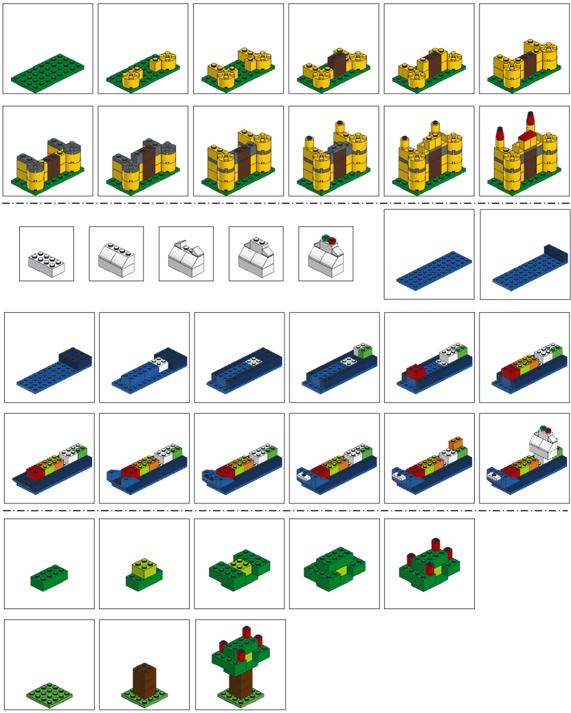
9 Step-by-Step Building Visualization
We visualize some sets that our model achieves 100% accuracy in Fig. 1.
References
- [1] et al, L.: Soft rasterizer: A differentiable renderer for image-based 3d reasoning. In: ICCV (2019)
- [2] Jones, B., Hildreth, D., Chen, D., Baran, I., Kim, V.G., Schulz, A.: Automate: A dataset and learning approach for automatic mating of cad assemblies. In: SIGGRAPH Asia (2021)
- [3] Loshchilov, I., Hutter, F.: Decoupled weight decay regularization. In: ICLR (2019)
- [4] Willis, K.D., Jayaraman, P.K., Chu, H., Tian, Y., Li, Y., Grandi, D., Sanghi, A., Tran, L., Lambourne, J.G., Solar-Lezama, A., et al.: Joinable: Learning bottom-up assembly of parametric cad joints. In: CVPR (2022)
- [5] Xiao, B., Wu, H., Wei, Y.: Simple baselines for human pose estimation and tracking. In: ECCV (2018)
- [6] Xiao, Y., Qiu, X., Langlois, P.A., Aubry, M., Marlet, R.: Pose from shape: Deep pose estimation for arbitrary 3d objects. In: BMVC (2019)