Exploiting High Quality Tactile Sensors for Simplified Grasping
Abstract
Robots are expected to grasp a wide range of objects varying in shape, weight or material type. Providing robots with tactile capabilities similar to humans is thus essential for applications involving human-to-robot or robot-to-robot interactions, particularly in those situations where a robot is expected to grasp and manipulate complex objects not previously encountered. A critical aspect for successful object grasp and manipulation is the use of high-quality fingertips equipped with multiple high-performance sensors, distributed appropriately across a specific contact surface.
In this paper we present a detailed analysis of the use of two different types of commercially available robotic fingertips (BioTac and WTS-FT), each of which is equipped with multiple sensors distributed across the fingertips’ contact surface. We further demonstrate that, due to the high performance of the fingertips, a complex adaptive grasping algorithm is not required for grasping of everyday objects. We conclude that a simple algorithm based on a proportional controller will suffice for many grasping applications, provided the relevant fingertips exhibit high sensitivity. In a quantified assessment, we also demonstrate that, due in part to the sensor distribution, the BioTac-based fingertip performs better than the WTS-FT device, in enabling lifting of loads up to 850g, and that the simple proportional controller can adapt the grasp even when the object is exposed to significant external vibrational challenges.
\helveticaboldgrasping, tactile sensing, WTS-FT fingertips, BioTac fingertips, adaptive grasp
1 Introduction
Humans use their five senses (i.e. touch, sight, hearing, smell and taste) for perceiving the world. The sense of touch is fundamental in enabling humans to perceive the surrounding environment Yeon et al. (2017). In particular, humans use touch for identifying an object’s physical properties, which are then used for fine and precise object manipulation Yeon et al. (2017). Humans have about 241 mechanoreceptors per square centimetre across different skin layers (cutaneous cues) for perceiving fine textural details. Mechanoreceptors in joints and tendons (kinesthetic cues) assist in geometric shape perception Rouhafzay and Cretu (2019).
Unlike humans, current robots have limited capability to perceive the world using the sense of touch and are therefore significantly restricted in performing everyday tasks, such as opening/closing bottles, opening/closing doors, or complex object manipulation. Robots also exhibit difficulties in grasping objects varying in shape, size and weight, particularly if the robot has no prior knowledge of the object or task in question. Because of its importance in sensory perception and action, the scientific community has been actively researching the development of the sense of touch for robots, but it currently lags behind advances in robot vision.
In this paper a comparative analysis of adaptive grasping and object handover using two types of commercially available tactile fingertips (fitted with different types of tactile sensing technologies) is provided. The two tactile fingertips were chosen as they are representative of devices in the moderate (WTS-FT) and high cost (BioTac) areas of commercially available sensors respectively. It is demonstrated that, due to the high performance of the BioTac fingertips, a complex adaptive grasping algorithm is not required for many grasping situations and a simple proportional controller will suffice, even when the object is subjected to significant perturbations (vigorous. shaking). The two types of fingertips are compared under the same test scenarios, where the object is placed in a target position and the robot arm moves toward the object, grasps it and transfers it to another location. The degree to which each set of fingertips can accommodate different weights and differently shaped loads is also assessed. The proposed adaptive grasping approach is independent of the type of fingertips being used, and exploits control of the three fingers used (i.e. thumb, index and ring) for grasping the objects. More details about the adaptive grasp, test scenarios and objects used for the grasp experiments are given in section 3. The paper structure is as follows: background information and related works are presented in section 2; the methodology is explained in section 3; experimental results are found in section 4; an analysis of the results may be seen in section 5; section 6 presents the discussion and conclusion; and future work is discussed in section 7.
2 Related work
The development of humanoid robots and/or robotic arms capable of sensing and perceiving the environment has attracted the interest of the scientific community for many decades. Recent trends in robotics illustrate the need for robots capable of grasping and manipulating complex shaped or delicate objects in resilient environments (i.e. farming, mining, medicine, manufacturing, nuclear and space) Government (2018). Artificial sensing perception aims to identify physical object properties (i.e. deformability, textural characteristics, stiffness, temperature, shape, weight, etc) which then can be used for pose estimation, improving the grasp quality and successful object manipulation. Chi et al. discussed state-of-the-art tactile sensing technologies (including capacitive, piezoresistive, piezoelectric, optical and inductive) and these are summarised in Table 1 ( Chi et al. (2018)).
|
Advantages | Disadvantages | |||||||||
| Capacitive |
|
|
|||||||||
| Piezoresistive |
|
|
|||||||||
| Piezoelectric |
|
|
|||||||||
| Optical |
|
|
|||||||||
| Inductive |
|
|
Kappassov et al. Kappassov et al. (2015) reviewed manipulation and grasping applications that involve touch perception and discussed pros and cons of each technique. Kappassov et al. focused his report on the analysis of the algorithms including grasp stability estimation, tactile object recognition, tactile servoing and force control. Despite the relevant contribution of Kappassov et al. Kappassov et al. (2015), the focus of the present paper is to compare state-of-the-art commercial-of-the-shelf fingertips using a single common control approach for uniformity, as opposed to comparing control algorithms-sensor combinations.
Bhandari and Lee Bhandari and Lee (2019) proposed an algorithm to control a robotic hand, acquiring pressure and vision data. Their algorithm uses TakkTile fingertips Takktile (2020. [Online]), which are low cost tactile sensors using micro-electromechanical systems (MEMS) barometers as pressure sensors, capable of detecting forces arising from masses of up to hundreds of grams Bhandari and Lee (2019). Although the TakkTile sensors are low cost, the fingertips are very limited, because they are composed of a single sensor, making it impossible to extract relevant information about the object’s spatial or textural properties. Another limitation of the proposed algorithm is that the camera must be perfectly aligned for detecting the object deformation. In contrast, in the present paper, the simple proportional control algorithm exploits multiple sensors per fingertip to enable adaptation of the grasp, while the object is being manipulated. Chorley et al. Chorley et al. (2009) proposed a biologically inspired tactile sensor composed of a thin flexible rubber skin, a highly compliant polymer melt blend and a camera facing an array of tracking markers (both the camera and the tracking markers are on the internal structure of the fingertip). The fingertip proposed in Chorley et al. (2009), is capable of encoding edge information which is crucial for the fine manipulation and exploration of objects. Such capabilities would be desirable when grasping and/or exploring objects; however the sensors are not commercially available.
Kerr et al. (Kerr et al. (2013), Kerr et al. (2014), Kerr et al. (2018)) proposed the use of the BioTac fingertips from Syntouch (2020. [Online]); these are robotic fingertips composed of 19 electrodes, AC/DC pressure and temperature transducers. Their research exhibits extensive work on material classification using the BioTac fingertips and different machine learning (ML) and artificial neural networks (ANN) techniques. The results in Kerr et al. (2018) are particularly interesting, because the solution proposed for material classification using the BioTac fingertips outperforms humans by over 16%, although this is in the context of tactile only (no vision) exploration. Gomez-Eguiluz et al. Gomez Eguiluz et al. (2018) proposed a recursive multimodal (vibration and thermal) tactile material identification approach using the BioTac fingertips and show it is possible to accurately classify the material type in about 0.28 seconds. In Gómez Eguíluz et al. (2019) the same authors incorporated the use of an effort controller to adapt the grasp forces, using BioTac sensors, when perturbations are detected. The algorithm classifies the force gradient to decide when to release the object in a handover context. Ottenhaus et al. (Ottenhaus et al. (2016), Ottenhaus et al. (2018)) proposed a method for haptic exploration through implicit surface modelling. WTS-FT fingertips Weiss-Robotics (2020. [Online]) composed of 32 capacitive cells uniformly distributed across the contact surface were used for collecting the tactile data (Ottenhaus et al. (2016), Ottenhaus et al. (2018)). These authors expanded the work initially presented in Ottenhaus et al. (2016) to propose a contact and surface orientation sensor concept, again for surface reconstruction, with a claimed mean reconstruction accuracy of 3.8mm (Ottenhaus et al. (2018)). Ke et al. (Ke et al. (2019)) presented a new anthropomorphic fingertip composed of a force sensing resistor (FSR) and polyvinylidene (PVDF) sensor modules with a claimed force measurement error of less than 5% , capable of distinguishing 5 different textures with an accuracy above 94%. More recently, Naganbandi et al. Nagabandi et al. (2019) proposed an online planning approach with deep dynamic models for in-hand object manipulation using the BioTac SP sensors. Nagabandi et al. (2019) reported that the model was able to coordinate multiple free-floating objects after learning from a dataset containing only four hours of synthetic videos performing the target tasks.
In this paper, the authors report on the development of an adaptive grasping algorithm compatible with different types of fingertips and capable of performing active grasp adaptation while moving the object from a source to a destination, while experiencing shaking perturbations. A number of grasp-related issues are investigated including the influence of the fingertips on the overall performance results and the possibility of completing the complex tasks using different types of sensors. The adaptive grasping algorithm was tested on both the BioTac and the WTS-FT fingertips which are commercially available.
3 Material and Methods
In this section, relevant aspects of the methodology are reported.
3.1 Robotic platform
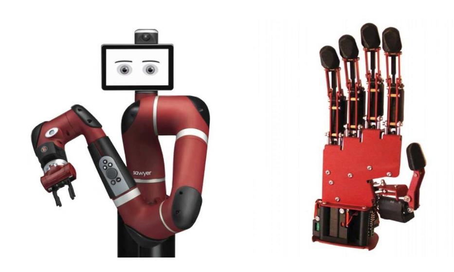
The Sawyer robot from Rethink-Robotics (2020. [Online]) is a collaborative robot that was designed for performing complex and accurate object pick-and-place tasks and was used in this work. Its arm (Figure 1) has 7 degrees of freedom, maximum reach of 1.26m, typical speed of 1.5 m/s and can lift payloads with a weight of up to 4Kg. An AR10 robotic hand from Active-8-Robots (2020. [Online]) was installed on the Sawyer robot and used in this work for grasping objects. The AR10 robotic hand (Figure 1) is a low-cost hand that features 10 degrees of freedom. As the WTS-FT fingertips are relatively large, and there isn’t sufficient space for operating all the AR10 fingers when the WTS-FT fingertips are installed on the index and ring fingers, the middle and small fingers were removed to allow for free movement of the remaining fingers.
3.2 Fingertips utilised
Two types of fingertips were used, namely the BioTac SP and WTS-FT sensors. The specifications of each type of fingertip are discussed below.
3.2.1 BioTac SP fingertips
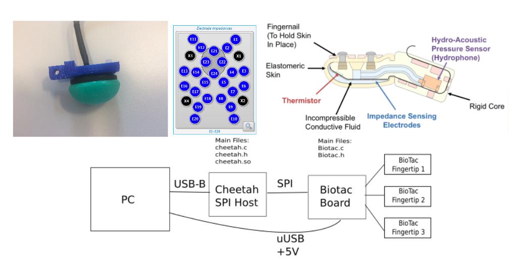
The Biotac SP fingertip from Syntouch (2020. [Online]) is a small (26x20x25mm) fingertip composed of an array of tactile sensors with a weight of 9.5g, capable of detecting information similar to human fingers (i.e. forces, micro-vibrations and temperature). Figure 2 depicts the BioTac SP sensor, and shows the fingertip’s sensor distribution.
Three sensory modalities are measured via three distinct types of transducers:
-
•
24 electrodes for detecting the synthetic skin deformation and forces applied directly to the area of contact.
-
•
AC/DC pressure (PAC/PDC) transducer for detecting the forces applied directly (area populated with electrodes) and indirectly (not detected by the electrodes) to the synthetic skin of the sensor.
-
•
AC/DC temperature (TAC/TDC) thermister for the detection of thermal gradients when in contact with different types of materials.
The sensors are distributed across the curved surface of the BioTac SP fingertips for improving the contact between the synthetic skin and the object. The electrodes are strategically positioned in the middle for detecting direct contacts with the object. Vibrations are detected by the DC pressure (PDC) signal (filtered using a built-in low pass filter) and the AC pressure (PAC) signal (filtered using a built-in band pass filter). The BioTac SP fingertips also provide DC temperature (TDC) and AC temperature (TAC) readings, which can be used for calculating the static and dynamic thermal gradients, and which will vary when the fingertip establishes contact with different types of materials. A cross-sectional view of the BioTac fingertips and distribution of the sensors across the BioTac SP fingertip surface are shown (top) in Fig.2.
The BioTac SP fingertips setup is depicted in Fig. 2 (bottom) where it can be seen that the fingertips connect to a Sensors PC via an SPI Host and a Biotac interface board. Each BioTaC SP fingertip is sampled at 4.4kHz and generates 864 bits per frame. The sampling rate per transducer is shown in Table 2.
| Sensor type | Number of transducers | Sampling Rate |
| Electrodes | 24 | 73Hz per Electrode |
| AC Pressure | 1 | 2.2kHz |
| DC Pressure | 1 | 73Hz |
| AC Temperature | 1 | 73Hz |
| DC Temperature | 1 | 73Hz |
Three BioTac SP fingertips were plugged to the AR10 robotic hand, one in each of the three fingers (i.e. thumb, index and ring fingers).
3.2.2 WTS-FT fingertips
The WTS-FT fingertip’s Weiss-Robotics (2020. [Online]) tactile sensors measure 52x28x26mm in size, have a weight of 25.8g and are composed of a 48 tactile sensing matrix array, exhibiting a human-like sensitivity with measurement speed of up to 400 frames per second. Figure 3 depicts a WTS-FT sensor (left), sensors map (middle) and the system setup (right).
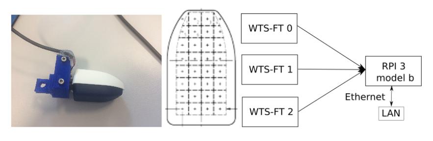
The WTS-FT fingertip sensors use a USB to serial interface and therefore it was necessary to develop an embedded system for capturing the fingertip data and send them across the Ethernet. A Raspberry Pi 3 model b was used for capturing the fingertips’ data over Ethernet (Raspberry Pi Foundation (2020)). Three WTS-FT fingertips were plugged into the AR10 robotic hand, one in each of the three fingers (i.e. thumb, index and ring fingers).
3.3 Vision system
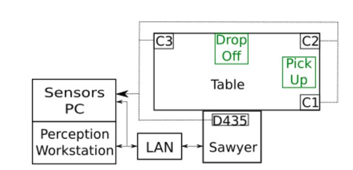
The Sawyer robot comes equipped with 2 cameras, one above the display installed on the top of the Sawyer Robot and another on the wrist. Despite having two cameras, the authors concluded that the position and type of the cameras were not ideal. Therefore, the authors installed a state-of-the-art Intel RealSense D435 depth camera from Intel (2020. [Online]) and three generic web cameras for capturing different angles of the grasp. The D435 depth camera was installed on the top of the Sawyer robot for capturing the image from above and could also be used for classifying objects using RGB and depth information. The four cameras were installed as depicted in Figure 4. Cameras C1, C2 and C3 are the generic cameras that were installed on the top of the table facing the pick-up position, while the D435 depth camera was installed facing the table (see Figure 4).
3.4 Grasped Objects
Five objects were select for measuring the quality of the grasp. Each object was selected to assess different abilities when the specific object was being grasped. Each object is manually placed in the grasping region without aligning the object to the robotic hand. The selected objects were:
-
•
Plastic cup - a deformable plastic object with the dimensions 9.5 5.3 12.5 cm used to evaluate the degree of deformation.
-
•
Tea cup - ceramic non-deformable object with the dimensions 888 cm.
-
•
Can - cylindrical object with the dimensions 7.97.925.9 cm made out of plastic and thin foil used to evaluate the grasp efficiency.
-
•
Water bottle - irregularly shaped, non-solid plastic object with the dimensions 7.38.710 cm used to evaluate the grasp efficiency.
-
•
Cubic box - this is a wooden cubic object with non-parallel sides with the dimensions 888 cm, chosen as a challenging object to evaluate the contact of the three fingers when an object with flat but non-parallel sides was grasped
The weight of each object was adjusted by adding either water or sugar as appropriate. A fail was recorded where the object is dropped at least 50% of the times (i.e. 5 times in 10 repetitions).
3.5 Software environment
A distributed computing system composed of a Perception Workstation (a high performance workstation equipped with 20 hyper-threaded cores (Intel Xeon processor), 64 GB of DDR4 and one NVIDIA GPU) was utilised for running the adaptive grasping and vision algorithms. The configuration also included a Sensors PC (a generic PC equipped with an Intel i5 quad-core and 8GB of DDR4) for collecting the sensors’ data (i.e. fingertips and cameras) and the Sawyer robot PC. All three computing platforms were running Ubuntu 16.04 LTS Ubuntu (2020. [Online]) and the Robotic Operating System (ROS) Kinetic ROS (2020. [Online]). OpenCV 4.0.1 OpenCV (2020. [Online]), a computer vision and machine learning framework was installed on the high performance workstation for processing the images being collected by the Sensors PC. The liberealsense SDK Realsense (2020. [Online]) was installed on the Sensors PC for aligning the Red, Green and Blue (RGB) and depth images captured by the D435 depth camera. The Intera SDK Robotics (2020. [Online]) , which is required for communicating with the Sawyer Robot, was installed on both the Perception Workstation and Sensors PC (see Figure 4).
3.6 Software Developed
Relevant aspects of the software developed are discussed in this section.
3.6.1 BioTac SP ROS stack
The BioTac SP fingertips are state-of-the-art fingertips but unfortunately did not have the required drivers or ROS package. The authors developed appropriate drivers and a ROS stack.
Each sensor of the BioTac SP fingertip’s has a resolution of 12 bits and a frequency response of 1.04 kHz, meaning that sensors are sensitive to high frequency noise. A simple low pass filter, described by equation 1, was implemented for filtering the BioTac SP fingertips readings.
| (1) |
where is the reading matrix of the fingertip for the time step , P is the percentage of the previous readings that should be retained (), is the sensor reading value of the the fingertip for the time step and is the sensor reading of the fingertip for the time step . The modulo of the difference between the A and r matrices (see equation 2) is computed for normalising the values (sensors with minimal variation will tend to 0 while sensors with a substantial variation will suffer a variation up to 200).
| (2) |
where is the modulo of the difference between and is the sum of the sensor reading of the fingertip.
The BioTac SP ROS stack is a distributed system where the fingertips data capture functionality runs on the Sensors PC and the data visualisation runs on the Perception Workstation.
3.6.2 WTS-FT ROS stack
The WTS-FT fingertips had drivers only available for Microsoft Windows. The authors wrote the Linux drivers, created a new WTS-FT ROS stack used for collecting the data generated by WTS-FT fingertips, publishing it into the respective ROS topics and displaying the results on the screen (see Fig. 7 and 11). These fingertips have a resolution of 12 bits and a readout rate of 400 frames per second. Unlike the BioTac SP fingertips, no extra filtering was required because the sensor cell’s output is linearly proportional to the applied force. The WTS-FT ROS stack is a distributed system, where the fingertips data capture runs on the Raspberry pi 3 model B (refer to Fig. 3) and the data visualisation runs on the Perception PC.
3.6.3 Object detection ROS stack
The Object Detection ROS stack is a generic package that was written for managing and processing the data collected by the cameras (refer to Fig 4). It is composed of (i) publishers that collect the data from the cameras and publish them on the target topics; (ii) a classification algorithm that classifies the object accordingly to its shape, (iii) visualisation windows that display the images captured from the cameras and classification results and (iv) a recording functionality used for recording the image sequences from the selected topics. The object detection ROS stack is a distributed system that runs on both the Sensors PC (functionality (i)) and on the Perception Workstation (functionalities (ii) to (iv)).
3.6.4 Sawyer Grasping Project ROS stack
The Sawyer Grasping Project (SGP) ROS stack (Machado et al. (2020a)) contains the simple adaptive grasping algorithm. The SGP ROS stack delivers the desirable fingertips type abstraction so that both types of fingertip are tested under the same testing conditions during the object grasping and relocation tasks. This stack includes (i) the main grasping and repositioning Algorithm 1, (ii) the adaptive grasping Algorithm 2, both shown overleaf, and (iii) the AR10 controller used for controlling the AR10 robotic hand fingers.
The process of grasping and repositioning an object (Algorithm 1) starts when a request for grasping a new object (sphere, cylinder, cuboid, prism and precision grasps) is received. The robotic arm moves from the home position to the pick up position using one of four pre-loaded grasps (sphere 3 fingers, large diameter, precision disk and precision sphere) from a pre-grasp library adapted from the grasp database reported by Saubayev et al. Saudabayev et al. (2018).
A proportional (P) controller, described by equation 3, was implemented for controlling the closure speed of the AR10 robotic hand. The P controller takes as input the robotic hand’s joints’ actual position and returns the next position as described by equation 3.
| (3) |
where is the output of the proportional controller, is the proportional gain, is the controller output with zero error and is the controller error which is given by equation 4,
| (4) |
where is the set point and is the measured process variable. The fingertips type abstraction is given through a functionality designated as contact detection. The contact detection takes the readings from the fingertips being used and compares the fingertip’s sensor reading to a threshold that was experimentally obtained for each type of fingertip. Contact is detected (equation 5) when at least 5 sensors (electrode, pressure, temperature in the case of the BioTac SP fingertips or force sensor cells in the case of WTS-FT) of a fingertip exceed a contact threshold . for the WTS-FT and BioTac was experimentally obtained based on the criteria of (i) lowest object deformation, (ii) highest grasp efficiency rate and (iii) highest slip resistance for a constant finger tracking force of 30N. The contact detection vector is a Boolean vector of dimension 3 (equal to the number of fingertips). The contact detection is given by equations 5 and 6.
| (5) |
where is the sensor value for fingertip and is the experimental threshold. It is considered that sensor is in contact with the object when .
| (6) |
where is the contact detector value for finger and the number of activated sensors. It is considered that fingertip is in contact with the object when .
The joint target position () is a vector containing the target position for each joint and has a dimension of 6 (two joints per finger and a total of 3 fingers).
The target position for the joint is given by the following pseudo-code:
if () and then
else if ( ) and then
else if () and then
else
end if
where , , and are the minimum, maximum, target position, actual position for a given joint , respectively.
The target position () is only updated when a given joint is in between the maximum () and minimum () allowed positions and no contact () is detected.
The grasp is completed when pseudo-code is satisfied for all the joints (i.e. ).
The continuous verification of the contact detection vector and the continuous adaptation of the finger’s joints for satisfying the condition using the the proportional controller, described by equation 3 is designated as the grasp adaptation.
Once an object is grasped, the grasp quality is subsequently assessed by picking the object up, shaking it and transporting it to a drop off position, while continuously performing the grasp adaptation.
The main algorithm, described in Algorithm 1, is composed of the following seven phases:
-
1.
The robot is idle awaiting for a new request;
-
2.
A new valid request is received and the robot moves the arm to the pick up position;
-
3.
The robot grasps the object;
-
4.
The object is lifted by the robot;
-
5.
The robot shakes the object;
-
6.
The object is transported to the drop-off position;
-
7.
The robot releases the object and goes to phase 1);
The activity encapsulated in phases 4 to 6 constitute the evaluation of the adaptive grasp. The adaptive grasp is a thread that checks the contact detection vector and adjusts (as far as possible) the fingers that may no longer be in contact with the object as a consequence of the type of arm movement, vibrations or object slippage. The main threads of the grasping algorithm are described in Algorithm 2.
The adaptive grasp algorithm is deliberately kept simple, as the hypothesis was that a simple algorithm would suffice provided high-performance sensor data were utilised. This proved to be the case (see the Results section). The algorithm was however optimised for parallelising all the tasks that could possibly be parallelised (e.g. reading fingertips, moving the arm and closing the hand).
3.7 Test scenario
It is important to evaluate both the grasp and the grasp adaptation under realistic conditions.The quality of the grasp was measured using generic tests designed for evaluating the motion and effort described by the Sawyer robot and AR10 hand fitted with either the Biotac SP or WTS-F fingertips (T). The tests also included a range of challenging grasp objects varying in shape, material, weight, texture and size. The test scenarios were divided into two types, namely, performance tests (measuring the motion and effort described by the hand with each type of object) and perturbation tests (evaluating the performance when grasping different types of objects under shaking perturbations). The perturbation test is composed of an acceleration of the speed from 0.1 rad/sec to 0.13 rad/sec, followed by two sequential oscillations in the horizontal axis followed by two sequential oscillations in the vertical axis, each with an amplitude of 10 degrees and a decrease of speed from the maximum of 0.13rad/sec to the initial 0.1 rad/sec.
Two tests were designed utilised to evaluate the grasps in this work, namely slip resistance and touch sensitivity in this work.
The slip resistance was measured using a millimetre scale installed on a cylindrical object (e.g. water bottle) attached to a spring balance when the object is pulled until it reaches the force threshold. The force threshold was set at a level large enough to cause the object to slip.
The touch sensitivity was measured by pushing a sponge against the sensor under test until contact was detected (i.e. until a value grater than 0 is registered).
4 Experimental results
In this section the experimental results obtained when performing the basic grasp performance and performance under object perturbation tests are reported.
4.1 Performance tests
The simple adaptive grasping algorithm shown in Algorithm 2 was utilised in all tests of touch sensitivity and slippage analysis. A sponge was used for measuring the minimum deformation required to establish contact with one finger (see Figure 5).
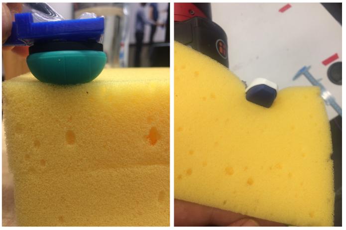
Figure 6 presents a scatter plot of slip distance versus force for both the Biotac and WTS equipped hands for the water bottle object. Slippage begins at an earlier force for the WTS sensors, as compared to the Biotac and increases more rapidly as the force is increased.
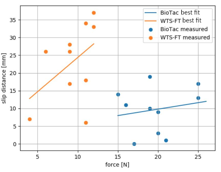
From the results shown in Figures 5 and 6 it is clear that the BioTac SP fingertips perform better than the WTS-FT fingertips in terms of touch sensitivity and slip prevention. The high sensitivity exhibited by the BioTaC devices enables the simple adaptive grasp algorithm to achieve better performance. Another factor that contributed to the better performance demonstrated by the BioTac SP fingertips was the circular fingertip shape that improves the contact when touching the object. Unlike the BioTac fingertips that are covered with a skin-like material, the WTS-FT are covered by a rubber-like material that does not adhere very well to the object surface, resulting in weaker grasps and an inability to lift heavier objects.
4.2 Performance under object perturbation
The results of the object perturbation tests are shown in Table 3. In each case, the object initially was grasped while empty and subsequently sugar or water (only in the case of the bottle) was added incrementally by 10g/10ml into the object to increase the weight until the object either slipped or dropped. For each weight, the object was then grasped, lifted and shaken (as shown in the yaw and pitch diagrams e.g. Figure 13). The maximum weight which the hand/fingertips combination was able to lift and retain, without slippage, while being actively shaken is given in columns 2 and 3 of Table 3, for the BioTac and WTS sensors respectively. The test results show that the BioTac SP fingertips performed equal to or better than the WTS-FT fingertips for all objects and the BioTac SP fingertips enabled the AR10 hand to grasp and lift heavier objects. The main reasons are related to the circular configuration of the BioTac SP fingertips that improves the contact of the fingertips’ sensors with the surface of the object. Also the rogusity of the BioTac’s skin increases the slip resistance. Note that in the case of the WTS sensors grasping the plastic bottle, once the weight exceeded 500g the sensors could not actually detect contact. This is due to the alteration of the bottle shape and the WTS-FT fingertip configuration.
| Description | BioTac SP results | WTS-FT results |
|---|---|---|
| Can | 850g | 300g |
| Cube Box | 450g | 350g |
| Tea cup | 500g | 400g |
| Plastic bottle | 510g | 510g∗ |
| Plastic cup | 350g | 350g |
∗contact with bottle lost when weight was increased from 500 to 510g due to the shape of the WTS-FT fingertips (see Figure 11)
4.3 Detailed analysis of fingertip performance
In this section, examples of the fingertips’ sensors and vibrations recordings, while utilising the simple adaptive grasping algorithm, are presented and analysed in more detail. The spatial representation is performed using a hot colour map (i.e. black [no contact], brown, red, orange, yellow and white [maximum contact]). An Inertial Measurements Unit (IMU) was installed on the back of the AR10 robotic hand for recording the yaw (horizontal vibrations) and pitch (vertical vibrations). Figure 7 depicts the recordings when grasping the empty cube using the WTS-FT sensors. Each colour refers to a specific sensor (one of 32) for the particular thumb, index or ring finger.
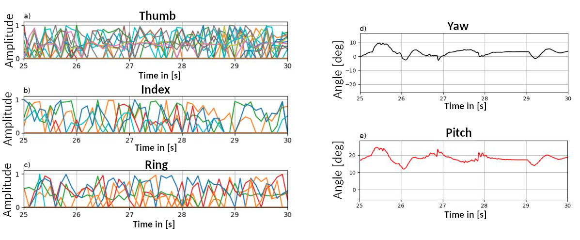
The plot of the yaw (d) and pitch (e) show the recorded vibrations during the shaking period. The Thumb, Index and Ring Fingertips’ sensors activation are shown in a), b) and c), respectively. Contact was detected when at least three sensors were activated (i.e. three coloured lines go above 30%). A full video of the grasp is available in Machado and McGinnity (2020b).
A spatio-temporal representation of the three fingertips during the shaking phase is shown in Figure 8.
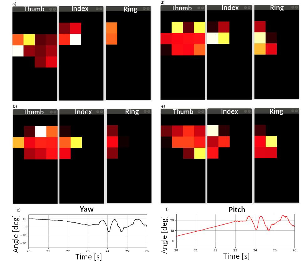
The spatial representation of the three fingertip’s (Thumb, Index and Ring) sensors were recorded at the timestamps 21, 22, 23 and 24 seconds (a, b, d and e) during the shaking phase. The 4 sequences of the fingertips sensors spacial representation shows grasp adaptation while the object is being shaken. Note that for example only two sensors are detecting pressure in the Ring fingertip at 21s (a), three sensors at 22s (b), five sensors at 23s (d) and five sensors at 24s (e). Furthermore note the variation in pressure applied to each fingertip’s sensor (colour variation). The recorded horizontal (c) and vertical (f) vibrations show the type of movements described by the robotic arm during the shaking phase.
Figure 9 depicts equivalent recordings when grasping the empty cube using the BioTac SP fingertips, showing the object vibration during the shaking phase, while the grasp was being adjusted..
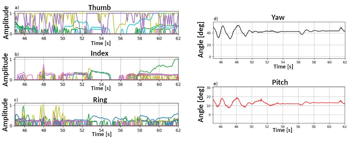
The plot of the yaw (d) and pitch (e) show the recorded vibrations during the shaking period. The Thumb, Index and Ring fingertips’ sensors activation are shown in a), b) and c), respectively. Contact was detected when when at least five sensors were activated (i.e. five coloured lines go above 30%). A full video of the grasp is available in Machado and McGinnity (2020a).
Figure 10
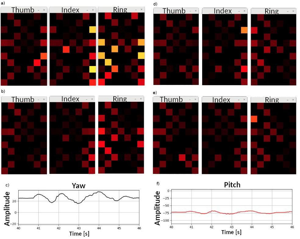
highlights the spatial representation of the fingertip’s sensors during the shaking phase. The spatial representation of the three fingertip’s (Thumb, Index and Ring) sensors were recorded at timestamps 41, 42, 43 and 44 seconds (a, b, d and e) during the shaking phase. The 4 sequences of the fingertips sensors spacial representation’s show grasp adaptation while the object is being shook. The recorded horizontal (c) and vertical (f) vibrations show the type of movements described by the robotic arm during the shaking phase. It is also clear that the contact (number of activated sensors per fingertip) between the BioTac SP fingertips (Figure 10) and the object is much better than the contact between the WTS-FT fingertips (Figure 8) and the object.
Figure 11 shows the recordings when grasping the bottle full of water using the WTS-FT fingertips
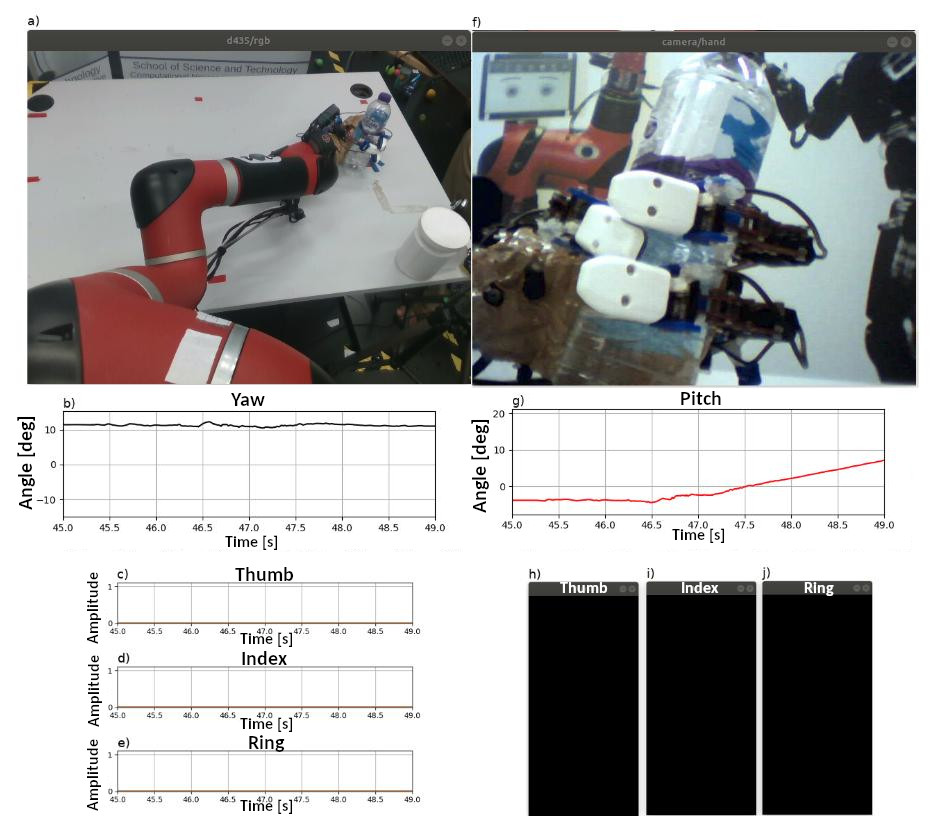
during the period of [45,46]s; the object was grasped because the water bottle was pushed against the palm of the robotic hand and the minimum joint thresholds reached (i.e. the joints reached the minimum joint positions). From the images a) and f) it is possible to infer that the sensors are touching the water bottle but from Figure 10c,10d,10e it is clear the sensors are not recording any reading. This is a consequence of the low sensitivity of the WTS-FT fingertips. None of the fingertips’ sensors (c, d and e) detected the bottle.
Figure 12 shows the equivalent recordings when grasping the bottle full of water using the BioTac SP fingertips.
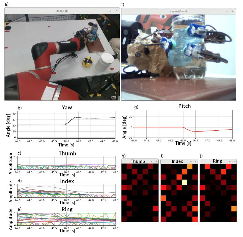
Figure 11 shows the object grasping which occurred during the period of [44,48]s; at least five sensors of each fingertip detected contact at 46s.The lift phase started 46s. The spatial representation of the three fingers show that the majority of the sensors are detecting the object.
5 Results analysis
The tests shown in Table 3 show that the BioTac SP fingertips performed better grasping the can, cube box and tea cup tests and had the same performance results in the plastic bottle and plastic cup test. We conclude that the BioTac fingertips allow for better grasping of the heavier objects. The WTS-FT fingertips have proven to be less sensitive than the Biotac SP fingertips (see Table 3). The main issues are related to the following:
-
1.
Size of the sensors (37.5 x 23.3 x 18.9 mm) - the WTS-FT are twice the size of the Biotac sensors and this therefore makes the fingers very long, which increases the complexity in closing the hand.
-
2.
Weight (15g) - The AR 10 robotic hand has to be calibrated more often with the WTS-FT fingertips because the weight of the WTS-FT require that the linear actuators (joints) work under more stress and therefore it was required to calibrate the AR10 more often when using the WTS-FT (about ten times) than the BioTac SP sensors (only one calibration required).
-
3.
Shape of sensor (flat) - this is the most relevant difference between the fingertips. The WTS-FT fingertips have no sensitivity on the edges, which prevents detection of small objects that slip between the fingers (e.g. soft ball or the black cylinder). The lack of edge detection of the WTS-FT also impacts on the stress applied to the linear actuators (joints) of the AR10 hand. During the experiments the authors had to replace 2 linear actuators that stopped working, because of excess force applied to close the fingers when objects were being grasped with the edges of the WTS-FT sensors.
-
4.
Surface material (rubber) - unlike the BioTac sensors, which use a skin like material (with a rugosity similar to human skin) with more adherence to the surface of the object, the WTS-FT have a rubber-like material which decreases the slip resistance.
Crucially, the experiments show that the simple control algorithm based on a proportional controller is quite capable of ensuring a robust grasp even when the object being grasped is significantly perturbed by shaking. This is the case for all the objects assessed. We conclude that this is only possible due to the sophistication and placements of the fingertip sensors, particularly in the case of the BioTac SP devices.
6 Discussion and Conclusion
This paper has considered the potential of modern tactile sensors in simplifying the requirements for adaptive grasp algorithms, compatible with different types of haptic technologies. A simple proportional controller based adaptive grasp algorithm was used while performing a comparative analysis between two state-of-the-art commercially available fingertips, namely, the BioTac SP and WTS-FT fingertips. A thorough analysis of sensor contacts’ strength, while grasping various objects, is provided. The results of this study show that the basic adaptive grasp algorithm is only limited by the quality of the sensory data collected by each fingertip type. The BioTac devices performed better than the WTS-FT in the majority of the tests. The geometry, skin-like material, variety of embedded sensor type, and data acquisition speed of the BioTac fingertips are all factors that contribute to such successful results. The WTS-FT fingertips were unable to pick up heavier objects, during a shaking test, and the heavy objects slipped more than when using the BioTac sensors. We consider that this arises, at least in part, because the control algorithm is starved of appropriate sensor feedback in the case of the WTS-FT sensors. We also conclude that WTS-FT fingertips are not suitable for grasping soft objects and are less tolerant to vibrations. Conversely, it is important to note that the WTS-FT fingertips are considerably less expensive than the BioTac SP fingertips.
The following ROS stacks were developed in this project:
-
1.
Sawyer Grasping project. The source code is available in the authors restricted repository Machado et al. (2020a).
-
2.
WTS-FT. The source code is publicly available in Machado et al. (2020b).
-
3.
BioTac SP. The source code is publicly available Machado and McGinnity (2020c).
-
4.
Object detection. The source code is stored on a private repository Machado and McGinnity (2020d).
7 Future Work
Future work is targeted at more extensive comparisons of tactile sensing fingertips and exploiting the BioTac sensors for tasks requiring fine object robot manipulation, i.e. tasks that can be easily performed by humans using the sophisticated tactile sensing capabilities of the human hand (e.g. tie different types of knots). Exploiting advanced touch capabilities to inform modern robot perception algorithms will also be an important future challenge.
References
- Active-8-Robots (2020. [Online]) Active-8-Robots (2020. [Online]). Ar10 robotic hand. Online
- Bhandari and Lee (2019) Bhandari, B. and Lee, M. (2019). Haptic identification of objects using tactile sensing and computer vision. Advances in Mechanical Engineering 11, 168781401984046. 10.1177/1687814019840468
- Chi et al. (2018) Chi, C., Sun, X., Xue, N., Li, T., and Liu, C. (2018). Recent Progress in Technologies for Tactile Sensors. Sensors 18, 948. 10.3390/s18040948
- Chorley et al. (2009) Chorley, C., Melhuish, C., Pipe, T., and Rossiter, J. (2009). Development of a tactile sensor based on biologically inspired edge encoding. 2009 International Conference on Advanced Robotics, ICAR 2009 , 1–6
- Gomez Eguiluz et al. (2018) Gomez Eguiluz, A., Rano, I., Coleman, S., and McGinnity, T. (2018). Multimodal Material Identification through Recursive Tactile Sensing. IEEE Robotics and Autonomous Systems
- Gómez Eguíluz et al. (2019) Gómez Eguíluz, A., Rañó, I., Coleman, S. A., and McGinnity, T. (2019). Reliable robotic handovers through tactile sensing. Autonomous Robots 10.1007/s10514-018-09823-2
- Government (2018) Government, U. (2018). Industrial Strategy
- Intel (2020. [Online]) Intel (2020. [Online]). Depth camera d435. Online
- Kappassov et al. (2015) Kappassov, Z., Corrales, J.-A., and Perdereau, V. (2015). Tactile sensing in dexterous robot hands — review. Robotics and Autonomous Systems 74, 195–220. https://doi.org/10.1016/j.robot.2015.07.015
- Ke et al. (2019) Ke, A., Huang, J., Chen, L., Gao, Z., Han, J., Wang, C., et al. (2019). Fingertip Tactile Sensor with Single Sensing Element Based on FSR and PVDF. IEEE Sensors Journal , 1–110.1109/JSEN.2019.2936304
- Kerr et al. (2013) Kerr, E., McGinnity, T., and Coleman, S. (2013). Material classification based on thermal properties - A robot and human evaluation. In 2013 IEEE International Conference on Robotics and Biomimetics, ROBIO 2013. 10.1109/ROBIO.2013.6739602
- Kerr et al. (2014) Kerr, E., McGinnity, T., and Coleman, S. (2014). Material classification based on thermal and surface texture properties evaluated against human performance. In 2014 13th International Conference on Control Automation Robotics and Vision, ICARCV 2014. 10.1109/ICARCV.2014.7064346
- Kerr et al. (2018) Kerr, E., McGinnity, T., and Coleman, S. (2018). Material recognition using tactile sensing. Expert Systems with Applications 10.1016/j.eswa.2017.10.045
- Machado and McGinnity (2020a) Machado and McGinnity (2020a). Enhanced grasp biotac sp cube trial 1. 10.5281/zenodo.3547726
- Machado and McGinnity (2020b) Machado and McGinnity (2020b). Enhanced grasp wts-ft cube trial 1. 10.5281/zenodo.3547596
- Machado et al. (2020a) Machado, P., Lama, N., and McGinnity, T. (2020a). Sawyer grasping project. https://doi.org/10.5281/zenodo.3529784. 10.5281/zenodo.3529784
- Machado et al. (2020b) Machado, P., Lama, N., and McGinnity, T. (2020b). Wts-ft ros package. https://doi.org/10.5281/zenodo.3529664. 10.5281/zenodo.3529664
- Machado and McGinnity (2020c) Machado, P. and McGinnity, T. (2020c). Biotac sp ros stack. https://doi.org/10.5281/zenodo.3529376. 10.5281/zenodo.3529376. N/A
- Machado and McGinnity (2020d) Machado, P. and McGinnity, T. (2020d). Object detection. https://doi.org/10.5281/zenodo.3529770. 10.5281/zenodo.3529770
- Nagabandi et al. (2019) Nagabandi, A., Konoglie, K., Levine, S., and Kumar, V. (2019). Deep Dynamics Models for Learning Dexterous Manipulation. In Robotics: Science and Systems 2018. 1–12
- OpenCV (2020. [Online]) OpenCV (2020. [Online]). Opencv. Online
- Ottenhaus et al. (2016) Ottenhaus, S., Miller, M., Schiebener, D., Vahrenkamp, N., and Asfour, T. (2016). Local implicit surface estimation for haptic exploration. In 2016 IEEE-RAS 16th International Conference on Humanoid Robots (Humanoids) (IEEE), 850–856. 10.1109/HUMANOIDS.2016.7803372
- Ottenhaus et al. (2018) Ottenhaus, S., Weiner, P., Kaul, L., Tulbure, A., and Asfour, T. (2018). Exploration and Reconstruction of Unknown Objects using a Novel Normal and Contact Sensor. In 2018 IEEE/RSJ International Conference on Intelligent Robots and Systems (IROS) (IEEE), 1614–1620. 10.1109/IROS.2018.8594272
- Raspberry Pi Foundation (2020) Raspberry Pi Foundation (2020). Buy a Raspberry Pi 3 Model B – Raspberry Pi. https://www.raspberrypi.org/products/raspberry-pi-3-model-b/
- Realsense (2020. [Online]) Realsense (2020. [Online]). Intelrealsense/librealsense. Online
- Rethink-Robotics (2020. [Online]) Rethink-Robotics (2020. [Online]). Sawyer robot. Online
- Robotics (2020. [Online]) Robotics, R. (2020. [Online]). Workstation setup - intera sdk. Online
- ROS (2020. [Online]) ROS (2020. [Online]). Ros kinetic. Online
- Rouhafzay and Cretu (2019) Rouhafzay, G. and Cretu, A.-M. (2019). A Visuo-Haptic Framework for Object Recognition Inspired by Human Tactile Perception. Proceedings 4, 47. 10.3390/ecsa-5-05754
- Saudabayev et al. (2018) Saudabayev, A., Rysbek, Z., Khassenova, R., and Varol, H. A. (2018). Human grasping database for activities of daily living with depth, color and kinematic data streams. Scientific Data 5, 180101. 10.1038/sdata.2018.101
- Syntouch (2020. [Online]) Syntouch (2020. [Online]). Biotac sp fingertip. Online
- Takktile (2020. [Online]) Takktile (2020. [Online]). Takkstrip basics - takktile. Online
- Ubuntu (2020. [Online]) Ubuntu (2020. [Online]). Ubuntu 16.04.6 lts (xenial xerus). Online
- Weiss-Robotics (2020. [Online]) Weiss-Robotics (2020. [Online]). Wts-ft fingertip. Online
- Yeon et al. (2017) Yeon, J., Kim, J., Ryu, J., Park, J.-Y., Chung, S.-C., and Kim, S.-P. (2017). Human Brain Activity Related to the Tactile Perception of Stickiness. Frontiers in Human Neuroscience 11, 8. 10.3389/fnhum.2017.00008