Generating coherent phonon waves in narrow-band materials: a twisted bilayer graphene phaser
Abstract
Twisted bilayer graphene (TBG) exhibits extremely low Fermi velocities for electrons, with the speed of sound surpassing the Fermi velocity. This regime enables the use of TBG for amplifying vibrational waves of the lattice through stimulated emission, following the same principles of operation of free-electron lasers. Our work proposes a lasing mechanism relying on the slow-electron bands to produce a coherent beam of acoustic phonons. We propose a device based on undulated electrons in TBG, which we dub the phaser. The device generates phonon beams in a terahertz (THz) frequency range, which can then be used to produce THz electromagnetic radiation. The ability to generate coherent phonons in solids breaks new ground in controlling quantum memories, probing quantum states, realizing non-equilibrium phases of matter, and designing new types of THz optical devices.
Introduction.—
Controlling and manipulating phonons is a long-sought goal offering a multitude of applications in electronics, information processing, and material science Först et al. (2011); Li et al. (2012); Balandin and Nika (2012); Maldovan (2013); Balandin (2020); Subedi et al. (2014); Mankowsky et al. (2016); Juraschek et al. (2017a), known as phononics. Recently, high-amplitude beams of phonons were employed to induce superconductivity Mankowsky et al. (2014); Mitrano et al. (2016); Knap et al. (2016); Komnik and Thorwart (2016); Babadi et al. (2017); Kennes et al. (2017); Cantaluppi et al. (2018); Liu et al. (2020) and to control ferroelectricity Mankowsky et al. (2017); Nova et al. (2019); Li et al. (2019); Shin et al. (2020); Abalmasov (2020) and magnetism Nova et al. (2016); Juraschek et al. (2017b); Shin et al. (2018); Radaelli (2018); Maehrlein et al. (2018); Gu and Rondinelli (2018); Khalsa and Benedek (2018); Fechner et al. (2018); Juraschek and Spaldin (2019); Disa et al. (2020); Juraschek and Narang (2020); Rodriguez-Vega et al. (2020); Juraschek et al. (2020, 2021); Stupakiewicz et al. (2021); Afanasiev et al. (2021). Developing reliable sources of phonons is therefore of key importance for future advances in the field of phononics. Generation of coherent phonons in solids can be achieved through pumping by intense laser and magnetic fields Miranda (1976); Nunes (1984a, b); Tronconi and Nunes (1986); Kittlaus et al. (2016), or by the acoustic Cherenkov effect Komirenko et al. (2000); Spector (1962); Komirenko et al. (2003); Shinokita et al. (2016).
A laser of phonons (i.e., a device for amplification of sound waves by stimulated emission) can serve as an efficient source of strong coherent acoustic waves with a narrow linewidth. Such devices were realized in the low-frequency range, from radio to gigahertz, in trapped ions Wallentowitz et al. (1996); Vahala et al. (2009); Ip et al. (2018), optical tweezers Pettit et al. (2019), nanomechanical resonators Grudinin et al. (2010); Jing et al. (2014); Chafatinos et al. (2020); Lü et al. (2017); Wang et al. (2017); Zhang et al. (2018), and magnetic systems Bargatin and Roukes (2003); Ding et al. (2019). A coherent amplification of terahertz (THz) phonons, yet below a threshold, was recently demonstrated in semiconductor superlattices Beardsley et al. (2010), and pump and probe experiments in silicon carbide Cartella et al. (2018).
Here, we present a model of a device for controlled amplification of acoustic phonons in the THz range, based on the newly-discovered narrow-band materials. We show that the unique bandstructures of such materials facilitate the amplification of coherent phonons in a narrow linewidth with low losses to incoherent modes. Furthermore, acoustic phonons have a long lifetime, giving rise to a high-gain and low-loss device Ghosh et al. (2008). Although phonon lasers are often referred to as “sasers” Zavtrak and Volkov (1997), we dub our narrow-band-based device a “phaser”, to highlight the quantum nature of the underlying mechanism.
Narrow-band materials were recently discovered in twisted bilayer graphene (TBG) Bistritzer and MacDonald (2011); Cao et al. (2018a, b) and other moiré heterostructures Ajayan et al. (2016); Balents et al. (2020). In the TBG, the electronic dispersion can be tuned by a variation of the twist angle, reaching nearly flat bands at the “magic” twist angle. At the same time, the spectrum of the acoustic phonons of the TBG near the magic angle is almost unaffected by the twist angle Koshino and Son (2019); Koshino and Nam (2020); Ishizuka et al. (2021), giving rise to the “slow-electron” regime in which the speed of sound surpasses the electronic group velocities Sharma et al. (2021). In this regime, the spontaneous emission of incoherent acoustic waves is suppressed by kinematic constrains.
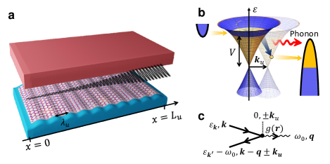
We describe the realization of the device in a TBG tuned close to the magic angle and weakly modulated in space by a periodic uniaxial strain or a periodic array of screening gates, see Fig. 1a. The periodicity of the modulation defines the resonant phonon mode of the phaser. Remarkably, for lasing in the THz range, the modulation wavelength should be in the mesoscopic scale. The electronic population inversion, necessary for the gain, is imposed by the external leads, in a structure similar to semiconductor laser diodes Amnon (1988).
Toy model.—
To develop an intuition for the lasing mechanism of the phaser, we begin by analyzing a toy model. Later, we numerically analyze the full band structure of the TBG, whose physics near the charge neutrality point can be described by this toy model. Yet, this model applies to more generic two-dimensional lattices in the slow-electron regime, with low-energy physics given by the Dirac Hamiltonian
| (1) |
where is the in-plane crystal momentum, is a vector of Pauli matrices acting in the pseudospin basis, and is the electronic group velocity. Eq. (1) is diagonalized by the Bloch states , where is periodic in the unit cell, corresponding to the eigenvalues , where and is the area of the system. The eigenstates are created by the operators . In the toy model, we assume no spin or pseudospin degrees other than (additional degrees of freedom such as valley, spin, and layer indices of the TBG would not qualitatively change the effect).
We consider a regime in which , where is the speed of sound in the material, assumed to be uniform and isotropic. The corresponding sound waves are described by the lattice displacement operator 111We do not consider the flexural modes of suspended graphene., which can be expanded in the eigenmodes . Here, , and is the unit vector denoting the direction of the displacement in the mode and crystal momentum . Focusing on the lowest energy acoustic mode with , we assume a dispersion , and coupling to electrons
| (2) |
Here, is a local electronic operator with and denotes the coupling strength assumed to be non-uniform in space. The spatial dependence of is specified below.
The system is connected to two external leads imposing population inversion for the electrons. The two leads are electron- and hole-doped semiconductors, with the bottom edge of the conduction band of the electron-doped semiconductor and the top edge of the valence band of the hole-doped semiconductor set at the energy . The chemical potential of the electron-doped semiconductor is set at , corresponding to the top of the upper band of the TBG [denoted by , see below Eq. (1)]. The chemical potential of the hole-doped semiconductor is set to the charge neutrality point of the TBG, . For simplicity, we assume that the tunneling rate of the electrons between the system and the leads is faster than the decay rate of the electrons in the system due to relaxation and phonon emission processes 222Otherwise one needs to compute the full electronic steady state in the presence of the tunneling from the leads and relaxation, which we leave for future investigation. With this assumption and for zero-temperature leads, the occupation probability of the electrons can be approximated by for , and otherwise, imposing an inverted population in the bottom of the upper band, see Fig. 1b.
Such an inverted population is virtually decoupled from the phonons to the leading order in the electron-phonon coupling when this coupling is spatially uniform. This is because, in the “slow-electron” regime, it is impossible to simultaneously conserve energy and crystal momentum in a single-phonon emission. Therefore, in this case, the incoherent phonon background field created by the non-equilibrium electronic state is suppressed compared to wide-band materials. This virtual decoupling between the electrons and the phonons provides an important baseline condition for lasing. However, the electrons should be coupled to at least one phonon mode, to generate a coherent beam.
Following the concept of free-electron lasers Madey (2003); Pellegrini et al. (2016); Friedman et al. (1988); Roberson and Sprangle (1998), emission in a selected mode can be induced by spatially modulated electron-phonon coupling coefficient, . In what follows, we consider a coupling modulated along the direction, with a wavelength , and uniform along , , see Fig. 1a for illustration. We denote the region of the system where , a nano-undulator, by analogy with a magnetic undulator in free-electron lasers. The physical realization of the nano-undulator in the TBG is discussed below.
In the nano-undulator, the conservation of crystal momentum in a phonon emission process obeys , where and are respectively the crystal momenta of the electron before and after the emission of a phonon with momentum , and [see Fig. 1c]. The additional momentum shift arises from the expansion of in its spatial Fourier components, , where . The phase shift of the electron-phonon components corresponds to a momentum shift in Eq. (2). In turn, the energy conservation is not affected by the static modulation of the coupling and reads . For phonons propagating in the -direction, the energy and crystal momentum conservation is satisfied by two resonant modes, with frequencies
| (3) |
This formula demonstrates that the resonant frequency of the laser can be controlled by tuning the modulation wavevector of the nano-undulator, .
Estimation of the gain.—
To estimate the gain of the device, we consider a coherent sound wave incident at with amplitude and frequency , propagating in the positive direction, see Fig. 1a. This sound wave can be generated i.e., by seeding from an external source or by spontaneous emission processes. We parametrize the amplification of the sound wave in the nano-undulator by an exponential factor with the gain coefficient Amnon (1988)
| (4) |
where . Such a sound wave, after propagating through the nano-undulator, carries a period-averaged power density of
| (5) |
where is the nano-undulator length along the direction, is the mass of the atoms comprising the lattice, and is the lattice constant.
This power is the result of the system steadily emitting acoustic phonons in the nano-undulator. In the low-gain limit, the period-averaged power density emitted by the electrons stimulated by the field , can be found using Fermi’s golden rule 333See supplemental material for derivation.,
| (6) |
Here, () and () respectively denote the electronic band and crystal momentum before and after the interaction with the acoustic wave and we defined , where the integration is over the area of the nano-undulator. We note that coherent phonon generation in a more generic case can be studied by analyzing electron-phonon instabilities of the equations of motion, as is outlined in the supplementary material. Given, that the sound wave is coherent, we can approximate the acoustic field operator in the expression for [Eq. (2)] by its expectation value , given in Eq. (4). Then we obtain , where , and is the -th component of the unit vector pointing in the direction of .
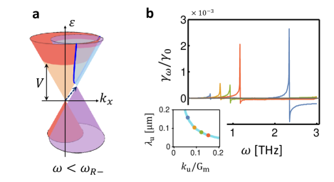
Assuming does not have a strong momentum dependence, and taking a small gain limit , is non-zero only when . In the thermodynamic limit (), the values of contributing to the sum in the expression for in Eq. (6), lie near the intersection line of two cones described by and , where , and , see Fig. 2a. The largest value of is obtained for , where [see Eq. (3)], where the two cones are tangent. The area in the momentum space where the two cones are nearly tangential diverges as , with , as approaches from below, giving rise to a resonance peak in . For the intersection line of the cone with and the cone with , contributes to a negative peak corresponding to the absorption of phonons.
The gain in the system, , can be found by setting and using the expressions of and as a function of [Eqs. (5) and (6)]. In the small gain limit (), we obtain
| (7) |
where . Estimating Eq. (6) in the limit and Note (3), we find
| (8) |
where and is the density of states of the Dirac dispersion. Fig. 2b shows as a function of for a few values of shown in the inset of this figure.
Realization of the phaser in the TBG.—
Having established the lasing mechanism for the toy model, we now discuss its realization in the TBG. The TBG consists of two graphene monolayers twisted by a relative angle , giving rise to a moiré supper lattice with the lattice constant Andrei and MacDonald (2020) . For small twist angles, the dispersion near the charge neutrality exhibits narrow bands, whose low-energy physics can be approximated by Eq. (1) with additional degenerate spin and valley quantum numbers Bistritzer and MacDonald (2011); Koshino et al. (2018). For concreteness, we focus on , where we found , which is below the speed of sound in the material, approximated here by . We consider two alternative realizations of a nano-undulator, through spatial mesoscopic modulation of the electron-phonon coupling [see Eq. (2)] 444A spatially modulated perturbation also modifies the electron and phonon dispersions, by opening minigaps at , which do not affect phase space region relevant for lasing..
The first realization is based on a spatially modulated uniaxial strain, as illustrated in Fig. 1a. Such a modulation can be realized by placing the TBG on an architected nanostructure or by applying temperature gradients Deng and Berry (2016); Frisenda et al. (2017); Ludacka et al. (2018); Banerjee et al. (2020); Hsu et al. (2020). Weak spatially periodic strain modulates the lattice geometry of each graphene monolayer, which in turn modulates the electron-phonon coupling Bi et al. (2019); Koshino and Nam (2020). For a strain applied along the -direction of the form , the spatially-modulated part of the electron-phonon coupling in each monolayer can be expressed by Eq. (2) with , and , where creates an electron in the sublattice A or B of the graphene monolayer at the unit cell located at Note (3). For strain, we estimate .
The second realization is based on a periodic array of metallic gates at distance from the TBG. The gates change the screening efficiency of the Coulomb interaction between the electronic charge density and the lattice ions Mariani and Von Oppen (2010); Hwang and Das Sarma (2007); Von Oppen et al. (2009); Suzuura and Ando (2002); Mañes (2007); Sohier et al. (2014); Park et al. (2014). For a phonon of momentum , we approximate the renormalized coupling term by , where is the distance from the gates, periodically changing between when above one of the gates and when is in the space between the gates; is the Thomas Fermi wavevector and the bare electron-phonon coupling. To approximate the electron-phonon coupling by Eq. (2), in the limit , we estimate and , where measures the density. For Kim et al. (2020) and , we estimate . For this value of , we obtain .
Numerical analysis of the gain.—
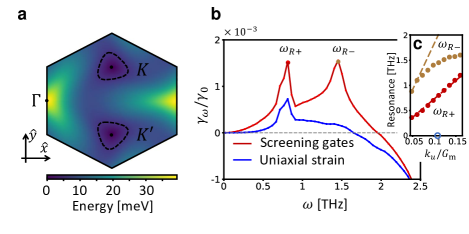
We numerically simulated the band structure of the TBG using the continuum model Bistritzer and MacDonald (2011); Koshino et al. (2018). Our goal was to verify that the full bandstructure of the TBG exhibits resonance peaks for phonon emission, as predicted by the toy model, and to compare their frequencies to Eq. (3). Fig. 3a shows the spectrum of the upper band of the TBG in a single valley in the mini-Brillouin zone centered around the Dirac points, see details in the supplementary material. The contours surrounding the and points indicate the equipotential curves .
We evaluated the gain in the full model of the TBG using Eq. (7), directly estimating by Eq. (6) in the two realizations of the nano-undulator, described above. Fig. 3b shows the numerically obtained gain as a function of the frequency for , where , for the two realizations of the nano-undulator. Both curves exhibit a peak near , corresponding to the analytical estimate of [defined in Eq. (3)]. The curve corresponding to an array of screening gates exhibits an additional peak near , which is missing in the curve of the uniaxial strain, due to the selection rules, suppressing the transitions for large phonon frequencies.
Fig. 3c shows the frequencies of the two resonances of the gain for the screening-gates realization of the nano-undulator as a function of . Dashed lines denote the analytical prediction of . The numerical curve of the low-frequency peak approximately coincides with the analytical curve corresponding to as a function of with [see Eq. (3)]. The position of the second peak does not show a linear dependence as a function of , as predicted by Eq. (3), due to deviations of the TBG band structure from the linear dispersion [Eq. (1)] for high phonon energies. We can fit its resonance frequency at , by with .
Lasing threshold.—
To lase, the device should reach the lasing threshold, i.e., the gain should exceed the loss. The loss of phonons mostly occurs due to electron-phonon, phonon-phonon, and impurity scattering. The lifetime of acoustic phonons in clean graphene can reach , for long-wavelength phonons Bonini et al. (2012), which results in . This value is below the gain of the system, estimated slightly above the resonance peak.
To have a sufficient gain, the system can be placed in an acoustic cavity. Such cavities were realized, e.g., in Ref. Maryam et al., 2013. The phonon-loss in a cavity is given by , where and are the reflectivities of the two mirrors. For and , we obtain . This results in a Q-factor of the cavity for the phonons of about .
Discussion.—
In this manuscript, we presented a model of a phonon laser device based on the “narrow-band” regime, dubbed a phaser. The phaser generates coherent phonon beams in the THz range. We demonstrated two realizations of the phaser in the TBG tuned near the magic angle, with a spatially modulated uniaxial strain and an array of screening gates [see Fig. 1a]. The periodicity of the structure can control the resonant frequency of the device. The phaser opens up new avenues in driving the TBG into a non-equilibrium regime through moiré Floquet engineering Katz et al. (2020); Rodriguez-Vega et al. (2021), extending the driving sources to THz frequencies and finite momenta Hübener et al. (2018).
The lattice oscillations caused by the phonon beam are coupled to plasmon modes through Coulomb interactions and the electron-phonon coupling. The resulting charged modes generate a THz electromagnetic field evanescent in the direction perpendicular to the TBG plane. We estimate the electric field amplitude near the surface Note (3) by . Here, denotes the relative charge fluctuation which we estimate as , and is the electronic density taken as . Assuming that the phaser in the saturation regime creates lattice waves of the order of , we estimate, . Such an electric field can be detected by placing a dipole antenna near the surface of the TBG. An oscillating evanescent electric field can be transformed into THz electromagnetic radiation, through a meta-material structure. We leave the analysis of this problem for future studies.
In our analysis, we focused on the single-particle electronic bands of the TBG. In the presence of the electron-electron interactions, the Fermi velocity may be renormalized, yet the slow-electron regime can be still achieved Goodwin et al. (2020). Furthermore, the Dirac dispersion near the charge neutrality point is protected by the symmetry (two-fold rotation times time-reversal) and will be preserved unless it is spontaneously broken Po et al. (2018).
The toy model of the phaser [Eq. (1)] can be realized in other experimental platforms. For example, a “slow-band” regime can be realized in cold atoms, using Bose-Fermi mixtures Illuminati and Albus (2004); Wang et al. (2005). We note, however, that the energy scales of cold atom setups are a few orders of magnitude smaller than in solids, giving rise to a different range of resonant frequencies.
Acknowledgements.
We thank Kenneth Burch, Jerome Faist, Mohammad Hafezi, Atac Imamoglu, Cyprian Lewandowski, Marios Michael, Leo Radzihovsky, and Christopher Yang for valuable discussions. G. Refael and I. Esin are grateful for support from the Simons Foundation and the Institute of Quantum Information and Matter, as well as support from the NSF DMR grant number 1839271. E. Demler and I. Esterlis acknowledge support from the ARO grant “Control of Many-Body States Using Strong Coherent Light-Matter Coupling in Terahertz Cavities”. This work is supported by ARO MURI Grant No. W911NF-16-1-0361, and was performed in part at Aspen Center for Physics, which is supported by National Science Foundation grant PHY-1607611.References
- Först et al. (2011) M. Först, C. Manzoni, S. Kaiser, Y. Tomioka, Y. Tokura, R. Merlin, and A. Cavalleri, “Nonlinear phononics as an ultrafast route to lattice control,” Nat. Phys. 7, 854–856 (2011).
- Li et al. (2012) Nianbei Li, Jie Ren, Lei Wang, Gang Zhang, Peter Hänggi, and Baowen Li, “Colloquium: Phononics: Manipulating heat flow with electronic analogs and beyond,” Rev. Mod. Phys. 84, 1045–1066 (2012).
- Balandin and Nika (2012) Alexander A. Balandin and Denis L. Nika, “Phononics in low-dimensional materials,” Mater. Today 15, 266–275 (2012).
- Maldovan (2013) Martin Maldovan, “Sound and heat revolutions in phononics,” Nature 503, 209–217 (2013).
- Balandin (2020) Alexander A. Balandin, “Phononics of Graphene and Related Materials,” ACS Nano 14, 5170–5178 (2020).
- Subedi et al. (2014) Alaska Subedi, Andrea Cavalleri, and Antoine Georges, “Theory of nonlinear phononics for coherent light control of solids,” Phys. Rev. B 89, 220301 (2014).
- Mankowsky et al. (2016) Roman Mankowsky, Michael Först, and Andrea Cavalleri, “Non-equilibrium control of complex solids by nonlinear phononics,” Reports Prog. Phys. 79, 064503 (2016).
- Juraschek et al. (2017a) D. M. Juraschek, M. Fechner, and N. A. Spaldin, “Ultrafast Structure Switching through Nonlinear Phononics,” Phys. Rev. Lett. 118, 054101 (2017a).
- Mankowsky et al. (2014) R. Mankowsky, A. Subedi, M. Först, S. O. Mariager, M. Chollet, H. T. Lemke, J. S. Robinson, J. M. Glownia, M. P. Minitti, A. Frano, M. Fechner, N. A. Spaldin, T. Loew, B. Keimer, A. Georges, and A. Cavalleri, “Nonlinear lattice dynamics as a basis for enhanced superconductivity in YBa2Cu3O6.5,” Nature 516, 71–73 (2014).
- Mitrano et al. (2016) M. Mitrano, A. Cantaluppi, D. Nicoletti, S. Kaiser, A. Perucchi, S. Lupi, P. Di Pietro, D. Pontiroli, M. Riccò, S. R. Clark, D. Jaksch, and A. Cavalleri, “Possible light-induced superconductivity in K3C60 at high temperature,” Nature 530, 461–464 (2016).
- Knap et al. (2016) Michael Knap, Mehrtash Babadi, Gil Refael, Ivar Martin, and Eugene Demler, “Dynamical Cooper pairing in nonequilibrium electron-phonon systems,” Phys. Rev. B 94, 214504 (2016).
- Komnik and Thorwart (2016) Andreas Komnik and Michael Thorwart, “BCS theory of driven superconductivity,” Eur. Phys. J. B 89, 1–5 (2016).
- Babadi et al. (2017) Mehrtash Babadi, Michael Knap, Ivar Martin, Gil Refael, and Eugene Demler, “Theory of parametrically amplified electron-phonon superconductivity,” Phys. Rev. B 96, 014512 (2017).
- Kennes et al. (2017) Dante M. Kennes, Eli Y. Wilner, David R. Reichman, and Andrew J. Millis, “Transient superconductivity from electronic squeezing of optically pumped phonons,” Nat. Phys. 13, 479–483 (2017).
- Cantaluppi et al. (2018) A. Cantaluppi, M. Buzzi, G. Jotzu, D. Nicoletti, M. Mitrano, D. Pontiroli, M. Riccò, A. Perucchi, P. Di Pietro, and A. Cavalleri, “Pressure tuning of light-induced superconductivity in K3C60,” Nat. Phys. 14, 837–841 (2018).
- Liu et al. (2020) B. Liu, M. Först, M. Fechner, D. Nicoletti, J. Porras, T. Loew, B. Keimer, and A. Cavalleri, “Pump frequency resonances for light-induced incipient superconductivity in YBa2Cu3 O6.5,” Phys. Rev. X 10, 011053 (2020).
- Mankowsky et al. (2017) R. Mankowsky, A. Von Hoegen, M. Först, and A. Cavalleri, “Ultrafast Reversal of the Ferroelectric Polarization,” Phys. Rev. Lett. 118, 197601 (2017).
- Nova et al. (2019) T. F. Nova, A. S. Disa, M. Fechner, and A. Cavalleri, “Metastable ferroelectricity in optically strained SrTiO3,” Science 364, 1075–1079 (2019).
- Li et al. (2019) Xian Li, Tian Qiu, Jiahao Zhang, Edoardo Baldini, Jian Lu, Andrew M. Rappe, and Keith A. Nelson, “Terahertz field–induced ferroelectricity in quantum paraelectric SrTiO3,” Science 364, 1079–1082 (2019).
- Shin et al. (2020) Dongbin Shin, Shunsuke A. Sato, Hannes Hübener, Umberto De Giovannini, Noejung Park, and Angel Rubio, “Dynamical amplification of electric polarization through nonlinear phononics in 2D SnTe,” npj Comput. Mater. 6, 1–8 (2020).
- Abalmasov (2020) Veniamin A. Abalmasov, “Ultrafast reversal of the ferroelectric polarization by a midinfrared pulse,” Phys. Rev. B 101, 014102 (2020).
- Nova et al. (2016) T. F. Nova, A. Cartella, A. Cantaluppi, M. Först, D. Bossini, R. V. Mikhaylovskiy, A. V. Kimel, R. Merlin, and A. Cavalleri, “An effective magnetic field from optically driven phonons,” Nat. Phys. 13, 132–136 (2016).
- Juraschek et al. (2017b) Dominik M. Juraschek, Michael Fechner, Alexander V. Balatsky, and Nicola A. Spaldin, “Dynamical multiferroicity,” Phys. Rev. Mater. 1, 014401 (2017b).
- Shin et al. (2018) Dongbin Shin, Hannes Hübener, Umberto De Giovannini, Hosub Jin, Angel Rubio, and Noejung Park, “Phonon-driven spin-Floquet magneto-valleytronics in MoS2,” Nat. Commun. 9, 1–8 (2018).
- Radaelli (2018) Paolo G. Radaelli, “Breaking symmetry with light: Ultrafast ferroelectricity and magnetism from three-phonon coupling,” Phys. Rev. B 97, 085145 (2018).
- Maehrlein et al. (2018) Sebastian F. Maehrlein, Ilie Radu, Pablo Maldonado, Alexander Paarmann, Michael Gensch, Alexandra M. Kalashnikova, Roman V. Pisarev, Martin Wolf, Peter M. Oppeneer, Joseph Barker, and Tobias Kampfrath, “Dissecting spin-phonon equilibration in ferrimagnetic insulators by ultrafast lattice excitation,” Sci. Adv. 4 (2018).
- Gu and Rondinelli (2018) Mingqiang Gu and James M. Rondinelli, “Nonlinear phononic control and emergent magnetism in Mott insulating titanates,” Phys. Rev. B 98, 024102 (2018).
- Khalsa and Benedek (2018) Guru Khalsa and Nicole A. Benedek, “Ultrafast optically induced ferromagnetic/anti-ferromagnetic phase transition in GdTiO3 from first principles,” npj Quantum Mater. 3, 1–8 (2018).
- Fechner et al. (2018) M. Fechner, A. Sukhov, L. Chotorlishvili, C. Kenel, J. Berakdar, and N. A. Spaldin, “Magnetophononics: Ultrafast spin control through the lattice,” Phys. Rev. Mater. 2, 064401 (2018).
- Juraschek and Spaldin (2019) Dominik M. Juraschek and Nicola A. Spaldin, “Orbital magnetic moments of phonons,” Phys. Rev. Mater. 3, 064405 (2019).
- Disa et al. (2020) Ankit S. Disa, Michael Fechner, Tobia F. Nova, Biaolong Liu, Michael Först, Dharmalingam Prabhakaran, Paolo G. Radaelli, and Andrea Cavalleri, “Polarizing an antiferromagnet by optical engineering of the crystal field,” Nat. Phys. 16, 937–941 (2020).
- Juraschek and Narang (2020) Dominik M. Juraschek and Prineha Narang, “Shaken not strained,” Nat. Phys. 16, 900–901 (2020).
- Rodriguez-Vega et al. (2020) M. Rodriguez-Vega, Ze Xun Lin, A. Leonardo, A. Ernst, G. Chaudhary, M. G. Vergniory, and Gregory A. Fiete, “Phonon-mediated dimensional crossover in bilayer Cr I3,” Phys. Rev. B 102, 081117 (2020).
- Juraschek et al. (2020) Dominik M. Juraschek, Prineha Narang, and Nicola A. Spaldin, “Phono-magnetic analogs to opto-magnetic effects,” Phys. Rev. Res. 2, 043035 (2020).
- Juraschek et al. (2021) Dominik M. Juraschek, Derek S. Wang, and Prineha Narang, “Sum-frequency excitation of coherent magnons,” Phys. Rev. B 103, 094407 (2021).
- Stupakiewicz et al. (2021) A. Stupakiewicz, C. S. Davies, K. Szerenos, D. Afanasiev, K. S. Rabinovich, A. V. Boris, A. Caviglia, A. V. Kimel, and A. Kirilyuk, “Ultrafast phononic switching of magnetization,” Nat. Phys. 17, 489–492 (2021).
- Afanasiev et al. (2021) D. Afanasiev, J. R. Hortensius, B. A. Ivanov, A. Sasani, E. Bousquet, Y. M. Blanter, R. V. Mikhaylovskiy, A. V. Kimel, and A. D. Caviglia, “Ultrafast control of magnetic interactions via light-driven phonons,” Nat. Mater. 20, 607–611 (2021).
- Miranda (1976) L. C.M. Miranda, “Phonon damping in the simultaneous presence of intense radiation and magnetic fields,” J. Phys. C 9, 2971 (1976).
- Nunes (1984a) O. A.C. Nunes, “Carrier-assisted laser pumping of optical phonons in semiconductors under strong magnetic fields,” Phys. Rev. B 29, 5679 (1984a).
- Nunes (1984b) O. A.C. Nunes, “Amplification of acoustic lattice vibrations by electrons in semiconductors under intense laser radiation,” J. Appl. Phys. 56, 2694 (1984b).
- Tronconi and Nunes (1986) A. L. Tronconi and O. A.C. Nunes, “Theory of the excitation and amplification of longitudinal-optical phonons in degenerate semiconductors under an intense laser field,” Phys. Rev. B 33, 4125 (1986).
- Kittlaus et al. (2016) Eric A. Kittlaus, Heedeuk Shin, and Peter T. Rakich, “Large Brillouin amplification in silicon,” Nat. Photonics 10, 463–467 (2016).
- Komirenko et al. (2000) S. M. Komirenko, K. W. Kim, A. A. Demidenko, V. A. Kochelap, and M. A. Stroscio, “Generation and amplification of sub-THz coherent acoustic phonons under the drift of two-dimensional electrons,” Phys. Rev. B 62, 7459 (2000).
- Spector (1962) Harold N. Spector, “Amplification of Acoustic Waves through Interaction with Conduction Electrons,” Phys. Rev. 127, 1084 (1962).
- Komirenko et al. (2003) M. Komirenko, W. Kim, A. Kochelap, V. Koroteev, and A. Stroscio, “Nonlinear regimes of coherent optical phonon generation in quantum wells under electric current pumping,” Phys. Rev. B 68, 155308 (2003).
- Shinokita et al. (2016) Keisuke Shinokita, Klaus Reimann, Michael Woerner, Thomas Elsaesser, Rudolf Hey, and Christos Flytzanis, “Strong Amplification of Coherent Acoustic Phonons by Intraminiband Currents in a Semiconductor Superlattice,” Phys. Rev. Lett. 116, 075504 (2016).
- Wallentowitz et al. (1996) S. Wallentowitz, W. Vogel, I. Siemers, and P. E. Toschek, “Vibrational amplification by stimulated emission of radiation,” Phys. Rev. A 54, 943 (1996).
- Vahala et al. (2009) K. Vahala, M. Herrmann, S. Knünz, V. Batteiger, G. Saathoff, T. W. Hänsch, and Th. Udem, “A phonon laser,” Nat. Phys. 5, 682–686 (2009).
- Ip et al. (2018) Michael Ip, Anthony Ransford, Andrew M. Jayich, Xueping Long, Conrad Roman, and Wesley C. Campbell, “Phonon Lasing from Optical Frequency Comb Illumination of Trapped Ions,” Phys. Rev. Lett. 121, 043201 (2018).
- Pettit et al. (2019) Robert M. Pettit, Wenchao Ge, P. Kumar, Danika R. Luntz-Martin, Justin T. Schultz, Levi P. Neukirch, M. Bhattacharya, and A. Nick Vamivakas, “An optical tweezer phonon laser,” Nat. Photonics 13, 402–405 (2019).
- Grudinin et al. (2010) Ivan S. Grudinin, Hansuek Lee, O. Painter, and Kerry J. Vahala, “Phonon laser action in a tunable two-level system,” Phys. Rev. Lett. 104, 083901 (2010).
- Jing et al. (2014) Hui Jing, S. K. Özdemir, Xin You Lü, Jing Zhang, Lan Yang, and Franco Nori, “PT -symmetric phonon laser,” Phys. Rev. Lett. 113, 053604 (2014).
- Chafatinos et al. (2020) D. L. Chafatinos, A. S. Kuznetsov, S. Anguiano, A. E. Bruchhausen, A. A. Reynoso, K. Biermann, P. V. Santos, and A. Fainstein, “Polariton-driven phonon laser,” Nat. Commun. 11, 1–8 (2020).
- Lü et al. (2017) H. Lü, S. K. Özdemir, L. M. Kuang, Franco Nori, and H. Jing, “Exceptional Points in Random-Defect Phonon Lasers,” Phys. Rev. Appl. 8, 044020 (2017).
- Wang et al. (2017) Guanzhong Wang, Min Xiao, Mingming Zhao, Xiaoshun Jiang, Yingchun Qin, and Zhangqi Yin, “Demonstration of an ultra-low-threshold phonon laser with coupled microtoroid resonators in vacuum,” Photonics Res. 5, 73–76 (2017).
- Zhang et al. (2018) Jing Zhang, Bo Peng, Şahin Kaya Özdemir, Kevin Pichler, Dmitry O. Krimer, Guangming Zhao, Franco Nori, Yu xi Liu, Stefan Rotter, and Lan Yang, “A phonon laser operating at an exceptional point,” Nat. Photonics 12, 479–484 (2018).
- Bargatin and Roukes (2003) Igor Bargatin and M. L. Roukes, “Nanomechanical analog of a laser: Amplification of mechanical oscillations by stimulated zeeman transitions,” Phys. Rev. Lett. 91, 138302 (2003).
- Ding et al. (2019) Ming Song Ding, Li Zheng, and Chong Li, “Phonon laser in a cavity magnomechanical system,” Sci. Rep. 9, 1–8 (2019).
- Beardsley et al. (2010) R. P. Beardsley, A. V. Akimov, M. Henini, and A. J. Kent, “Coherent terahertz sound amplification and spectral line narrowing in a stark ladder superlattice,” Phys. Rev. Lett. 104, 085501 (2010).
- Cartella et al. (2018) A. Cartella, T. F. Nova, M. Fechner, R. Merlin, and A. Cavalleri, “Parametric amplification of optical phonons,” Proc. Natl. Acad. Sci. 115, 12148–12151 (2018).
- Ghosh et al. (2008) S. Ghosh, I. Calizo, D. Teweldebrhan, E. P. Pokatilov, D. L. Nika, A. A. Balandin, W. Bao, F. Miao, and C. N. Lau, “Extremely high thermal conductivity of graphene: Prospects for thermal management applications in nanoelectronic circuits,” Appl. Phys. Lett. 92, 151911 (2008).
- Zavtrak and Volkov (1997) S. T. Zavtrak and I. V. Volkov, “Sasers (sound amplification by stimulated emission of radiation) in the nonlinear operating regime with various emitters,” Tech. Phys. 42, 793–796 (1997).
- Bistritzer and MacDonald (2011) Rafi Bistritzer and Allan H. MacDonald, “Moiré bands in twisted double-layer graphene,” Proc. Natl. Acad. Sci. 108, 12233–12237 (2011).
- Cao et al. (2018a) Yuan Cao, Valla Fatemi, Ahmet Demir, Shiang Fang, Spencer L. Tomarken, Jason Y. Luo, Javier D. Sanchez-Yamagishi, Kenji Watanabe, Takashi Taniguchi, Efthimios Kaxiras, Ray C. Ashoori, and Pablo Jarillo-Herrero, “Correlated insulator behaviour at half-filling in magic-angle graphene superlattices,” Nature 556, 80–84 (2018a).
- Cao et al. (2018b) Yuan Cao, Valla Fatemi, Shiang Fang, Kenji Watanabe, Takashi Taniguchi, Efthimios Kaxiras, and Pablo Jarillo-Herrero, “Unconventional superconductivity in magic-angle graphene superlattices,” Nature 556, 43–50 (2018b).
- Ajayan et al. (2016) Pulickel Ajayan, Philip Kim, and Kaustav Banerjee, “Two-dimensional van der Waals materials,” Phys. Today 69, 38 (2016).
- Balents et al. (2020) Leon Balents, Cory R. Dean, Dmitri K. Efetov, and Andrea F. Young, “Superconductivity and strong correlations in moiré flat bands,” Nat. Phys. 16, 725–733 (2020).
- Koshino and Son (2019) Mikito Koshino and Young-Woo Son, “Moiré phonons in twisted bilayer graphene,” Phys. Rev. B 100, 075416 (2019).
- Koshino and Nam (2020) Mikito Koshino and Nguyen N.T. Nam, “Effective continuum model for relaxed twisted bilayer graphene and moiré electron-phonon interaction,” Phys. Rev. B 101, 195425 (2020).
- Ishizuka et al. (2021) Hiroaki Ishizuka, Ali Fahimniya, Francisco Guinea, and Leonid Levitov, “Purcell-like Enhancement of Electron-Phonon Interactions in Long-Period Superlattices: Linear-Temperature Resistivity and Cooling Power,” Nano Lett. 21, 7465–7471 (2021).
- Sharma et al. (2021) Girish Sharma, Indra Yudhistira, Nilotpal Chakraborty, Derek Y.H. Ho, M. M.Al Ezzi, Michael S. Fuhrer, Giovanni Vignale, and Shaffique Adam, “Carrier transport theory for twisted bilayer graphene in the metallic regime,” Nat. Commun. 12, 1–11 (2021).
- Amnon (1988) Yariv Amnon, Quantim Electronics (JOHN WILET & SONS ,INC ., 1988).
- Note (1) We do not consider the flexural modes of suspended graphene.
- Note (2) Otherwise one needs to compute the full electronic steady state in the presence of the tunneling from the leads and relaxation, which we leave for future investigation.
- Madey (2003) John M.J. Madey, “Stimulated Emission of Bremsstrahlung in a Periodic Magnetic Field,” J. Appl. Phys. 42, 1906 (2003).
- Pellegrini et al. (2016) C. Pellegrini, A. Marinelli, and S. Reiche, “The physics of x-ray free-electron lasers,” Rev. Mod. Phys. 88, 015006 (2016).
- Friedman et al. (1988) A. Friedman, A. Gover, G. Kurizki, S. Ruschin, and A. Yariv, “Spontaneous and stimulated emission from quasifree electrons,” Rev. Mod. Phys. 60, 471 (1988).
- Roberson and Sprangle (1998) C. W. Roberson and P. Sprangle, “A review of free‐electron lasers,” Phys. Fluids B 1, 3 (1998).
- Note (3) See supplemental material for derivation.
- Andrei and MacDonald (2020) Eva Y. Andrei and Allan H. MacDonald, “Graphene bilayers with a twist,” Nat. Mater. 19, 1265–1275 (2020).
- Koshino et al. (2018) Mikito Koshino, Noah F.Q. Yuan, Takashi Koretsune, Masayuki Ochi, Kazuhiko Kuroki, and Liang Fu, “Maximally Localized Wannier Orbitals and the Extended Hubbard Model for Twisted Bilayer Graphene,” Phys. Rev. X 8, 031087 (2018).
- Note (4) A spatially modulated perturbation also modifies the electron and phonon dispersions, by opening minigaps at , which do not affect phase space region relevant for lasing.
- Deng and Berry (2016) Shikai Deng and Vikas Berry, “Wrinkled, rippled and crumpled graphene: An overview of formation mechanism, electronic properties, and applications,” Mater. Today 19, 197–212 (2016).
- Frisenda et al. (2017) Riccardo Frisenda, Matthias Drüppel, Robert Schmidt, Steffen Michaelis de Vasconcellos, David Perez de Lara, Rudolf Bratschitsch, Michael Rohlfing, and Andres Castellanos-Gomez, “Biaxial strain tuning of the optical properties of single-layer transition metal dichalcogenides,” npj 2D Mater. Appl. 1, 1–7 (2017).
- Ludacka et al. (2018) U. Ludacka, M. R.A. Monazam, C. Rentenberger, M. Friedrich, U. Stefanelli, J. C. Meyer, and J. Kotakoski, “In situ control of graphene ripples and strain in the electron microscope,” npj 2D Mater. Appl. 2, 1–6 (2018).
- Banerjee et al. (2020) Riju Banerjee, Viet Hung Nguyen, Tomotaroh Granzier-Nakajima, Lavish Pabbi, Aurelien Lherbier, Anna Ruth Binion, Jean Christophe Charlier, Mauricio Terrones, and Eric William Hudson, “Strain Modulated Superlattices in Graphene,” Nano Lett. 20, 3113–3121 (2020).
- Hsu et al. (2020) C. C. Hsu, M. L. Teague, J. Q. Wang, and N. C. Yeh, “Nanoscale strain engineering of giant pseudo-magnetic fields, valley polarization, and topological channels in graphene,” Sci. Adv. 6 (2020).
- Bi et al. (2019) Zhen Bi, Noah F.Q. Yuan, and Liang Fu, “Designing flat bands by strain,” Phys. Rev. B 100, 035448 (2019).
- Mariani and Von Oppen (2010) Eros Mariani and Felix Von Oppen, “Temperature-dependent resistivity of suspended graphene,” Phys. Rev. B 82, 195403 (2010).
- Hwang and Das Sarma (2007) E. H. Hwang and S. Das Sarma, “Dielectric function, screening, and plasmons in two-dimensional graphene,” Phys. Rev. B 75, 205418 (2007).
- Von Oppen et al. (2009) Felix Von Oppen, Francisco Guinea, and Eros Mariani, “Synthetic electric fields and phonon damping in carbon nanotubes and graphene,” Phys. Rev. B 80, 075420 (2009).
- Suzuura and Ando (2002) Hidekatsu Suzuura and Tsuneya Ando, “Phonons and electron-phonon scattering in carbon nanotubes,” Phys. Rev. B 65, 235412 (2002).
- Mañes (2007) J. L. Mañes, “Symmetry-based approach to electron-phonon interactions in graphene,” Phys. Rev. B 76, 045430 (2007).
- Sohier et al. (2014) Thibault Sohier, Matteo Calandra, Cheol Hwan Park, Nicola Bonini, Nicola Marzari, and Francesco Mauri, “Phonon-limited resistivity of graphene by first-principles calculations: Electron-phonon interactions, strain-induced gauge field, and Boltzmann equation,” Phys. Rev. B 90, 125414 (2014).
- Park et al. (2014) Cheol Hwan Park, Nicola Bonini, Thibault Sohier, Georgy Samsonidze, Boris Kozinsky, Matteo Calandra, Francesco Mauri, and Nicola Marzari, “Electron–Phonon Interactions and the Intrinsic Electrical Resistivity of Graphene,” Nano Lett. 14, 1113–1119 (2014).
- Kim et al. (2020) M. Kim, S. G. Xu, A. I. Berdyugin, A. Principi, S. Slizovskiy, N. Xin, P. Kumaravadivel, W. Kuang, M. Hamer, R. Krishna Kumar, R. V. Gorbachev, K. Watanabe, T. Taniguchi, I. V. Grigorieva, V. I. Fal’ko, M. Polini, and A. K. Geim, “Control of electron-electron interaction in graphene by proximity screening,” Nat. Commun. 11, 1–6 (2020).
- Bonini et al. (2012) Nicola Bonini, Jivtesh Garg, and Nicola Marzari, “Acoustic phonon lifetimes and thermal transport in free-standing and strained graphene,” Nano Lett. 12, 2673–2678 (2012).
- Maryam et al. (2013) W. Maryam, A. V. Akimov, R. P. Campion, and A. J. Kent, “Dynamics of a vertical cavity quantum cascade phonon laser structure,” Nat. Commun. 4, 1–6 (2013).
- Katz et al. (2020) Or Katz, Gil Refael, and Netanel H. Lindner, “Optically induced flat bands in twisted bilayer graphene,” Phys. Rev. B 102, 155123 (2020).
- Rodriguez-Vega et al. (2021) Martin Rodriguez-Vega, Michael Vogl, and Gregory A. Fiete, “Low-frequency and Moiré–Floquet engineering: A review,” Ann. Phys. (N. Y). 435, 168434 (2021).
- Hübener et al. (2018) Hannes Hübener, Umberto De Giovannini, and Angel Rubio, “Phonon Driven Floquet Matter,” Nano Lett. 18, 1535–1542 (2018).
- Goodwin et al. (2020) Zachary A.H. Goodwin, Valerio Vitale, Xia Liang, Arash A. Mostofi, and Johannes Lischner, “Hartree theory calculations of quasiparticle properties in twisted bilayer graphene,” Electron. Struct. 2, 034001 (2020).
- Po et al. (2018) Hoi Chun Po, Liujun Zou, Ashvin Vishwanath, and T. Senthil, “Origin of Mott Insulating Behavior and Superconductivity in Twisted Bilayer Graphene,” Phys. Rev. X 8, 031089 (2018).
- Illuminati and Albus (2004) Fabrizio Illuminati and Alexander Albus, “High-temperature atomic superfluidity in lattice Bose-Fermi mixtures,” Phys. Rev. Lett. 93, 090406 (2004).
- Wang et al. (2005) D. W. Wang, M. D. Lukin, and E. Demler, “Engineering superfluidity in Bose-Fermi mixtures of ultracold atoms,” Phys. Rev. A 72, 051604 (2005).