11email: Yue.Sun001@umb.edu22institutetext: The Department of Engineering, UMass Boston, USA
22email: Honggang.Zhang@umb.edu33institutetext: The Department of Engineering, UMass Boston, USA
33email: Zhuoming.Huang001@umb.edu44institutetext: The Department of Computer Science, UMass Lowell, USA
44email: bliu@cs.uml.edu
R2P: A Deep Learning Model from mmWave Radar to Point Cloud
Abstract
Recent research has shown the effectiveness of mmWave radar sensing for object detection in low visibility environments, which makes it an ideal technique in autonomous navigation systems. In this paper, we introduce Radar to Point Cloud (R2P), a deep learning model that generates smooth, dense, and highly accurate point cloud representation of a 3D object with fine geometry details, based on rough and sparse point clouds with incorrect points obtained from mmWave radar. These input point clouds are converted from the 2D depth images that are generated from raw mmWave radar sensor data, characterized by inconsistency, and orientation and shape errors. R2P utilizes an architecture of two sequential deep learning encoder-decoder blocks to extract the essential features of those radar-based input point clouds of an object when observed from multiple viewpoints, and to ensure the internal consistency of a generated output point cloud and its accurate and detailed shape reconstruction of the original object. We implement R2P to replace the Stage 2 of our recently proposed 3DRIMR (3D Reconstruction and Imaging via mmWave Radar) system. Our experiments demonstrate the significant performance improvement of R2P over the popular existing methods such as PointNet, PCN, and the original 3DRIMR design.
Keywords:
3D Reconstruction Point Cloud Deep Learning mmWave Radar.1 INTRODUCTION
Recently the advantage of Millimeter Wave (mmWave) radar in object sensing in low visibility environment has been actively studied and applied in autonomous vehicles [5] and search/rescue in high risk areas [10]. However, further application of mmWave radar in object imaging and reconstruction is quite difficult because of the characteristics of mmWave radar signals such as low resolution, sparsity, and large noise due to multi-path and specularity. Recent work [5, 3, 10] attempts to design deep learning systems to generate 2D depth images based on mmWave radar signals. 3DRIMR [20] further introduces an architecture that generates 3D object shapes based on mmWave radar, but there is still room for significant improvement in order to produce more satisfactory end results.
In this paper, we introduce Radar to Point Clouds (R2P), a deep learning model that generates 3D objects in the format of dense and smooth point clouds that accurately resemble the 3D shapes of original objects with fine details. The inputs to R2P are simply some rough and sparse point clouds with possibly many inaccurate points due to the imperfect conversion from raw mmWave radar data. For example, they can be directly converted from those 2D depth images generated from radar data, using systems such as [5] or the Stage 1 of 3DRIMR [20]. R2P can be used to replace the generator network in Stage 2 of 3DRIMR. Recall that 3DRIMR’s Stage 1 takes 3D radar intensity data as input and generates 2D depth images of an object, which are then combined and converted to a rough and sparse point cloud to be used as the input to Stage 2. The generator network of Stage 2 outputs the 3D shape of the object in the form of dense and smooth point cloud. Even though 3DRIMR can give some promising results, its Stage 2’s generator network design is still not quite satisfactory. Specifically, the edges of generated point clouds are still blurry and their points tend to be evenly distributed in space and thus do not give a clear sharp shape structure. We introduce R2P in this paper to replace the Stage 2 of the original 3DRIMR, and we find that R2P significantly outperforms 3DRIMR both quantitatively and visually.
Our major contributions are summarized as follows. We propose Radar to Point Cloud (R2P), a deep neural network model, to generate smooth, dense, and highly accurate point cloud representation of a 3D object with fine geometry details, based on rough and sparse point clouds with incorrect points. These input point clouds are directly converted from the 2D depth images of an object that are generated from raw mmWave radar sensor data, and thus characterized by mutual inconsistency and orientation/shape errors, due to the imperfect process to generate them. R2P utilizes an architecture of two sequential deep learning encoder-decoder blocks to extract the essential features of those input point clouds of an object when observed from various viewpoints, and to ensure the internal consistency of a generated output point cloud and its detailed shape reconstruction of the original object. We further demonstrate with extensive experiments the importance of loss function design in the training of models for reconstructing point clouds. We also show the limitations of Chamfer Distance (CD) and Earth Mover’s Distance (EMD), the two state-of-the-art point clouds evaluation metrics, in the evaluation of the shape similarity of two point clouds.
2 RELATED WORK
Frequency Modulated Continuous Wave (FMCW) Millimeter Wave (mmWave) radar sensing has been an active research area in recent years, especially in applications such as person/gesture identification [25, 29], car detection/imaging [5], and environment sensing [10, 3]. Usually Synthetic Aperture Radar (SAR) is used in data collection for high resolution, e.g., [11, 15, 4, 17]. This paper is built on our recent work [20] on applying mmWave radar for 3D object reconstruction, in which we proposed 3DRIMR. The deep neural network model proposed in this paper can replace the model in the Stage 2 of 3DRIMR, and this new model significantly outperforms the original 3DRIMR. There have been a few recent work on mmWave radar based imaging, mapping, and 3D object reconstruction [5, 3, 10, 30, 13]. Our work is inspired by their promising research results, especially PointNet [13, 14] and PCN [30]. Due to the low cost and small form factor of commodity mmWave radar sensors, we plan to develop a simple 3D reconstruction system with fast data collection to be attached in our UAV SLAM system [21] for search and rescue in dangerous environment. Besides radar signals, vision community has also been working on learning-based 3D object shape reconstruction [28, 1, 16, 18], most of which use voxels to represent 3D objects. Our proposed neural network model uses point cloud as a format for 3D objects to capture detailed geometric information with efficient memory and computation performance. Our proposed R2P significantly outperforms the existing methods such as PointNet [13], PointNet++ [14], PCN[30], and 3DRIMR [20].
3 PRELIMINARIES
3.1 FMCW Millimeter Wave Radar Sensing and Imaging
Similar to [20], we use FMCW mmWave radar sensor [23] signals to reconstruct 3D object shapes. Fast Fourier Transform (FFT) along three directions are conducted on received waveforms to generate 3D intensity maps of a space that represent the energy or radar intensity per voxel in the space, written as . Note that , , and represent azimuth angle, elevation angle, and range respectively. We use IWR6843ISK [24] operating at GHz frequency, and for high resolution radar signals, we adopt SAR operation. Unlike data from LiDAR and camera sensor, mmWave radar sensors can only give us sparse, low resolution, and highly noisy data. Incorrect ghost points in radar signals can be generated due to multi-path effect. References [5, 3, 10] give more detailed discussion on FMCW mmWave radar sensing.
3.2 Representation of 3D Objects
We adopt point cloud format to represent 3D objects. Even though point cloud is a standard representation of 3D objects and it is used in learning-based 3D reconstruction, e.g., [2, 13, 14], the convolutional operation of Convolutional Neural Network (CNN) cannot be directly applied to a point cloud set as it is essentially an unordered point set. Furthermore, the point cloud of an object that is directly generated by raw radar signals is not a good choice to represent the shape of an object because of radar signal’s low resolution, sparsity, and incorrect ghost points due to multi-path effect. Besides point clouds, voxel-based representations can also be used in 3D reconstruction [8, 12, 7, 27], and the advantage of such representation is that 3D CNN convolutional operations can be applied. In addition, mesh representations of 3D objects are also used in existing work [9, 26]. However these two representation formats are limited by memory and computation cost.
3.3 Review of 3DRIMR Architecture
This paper introduces R2P as a generator network to replace the Stage 2 of 3DRIMR in order to generate smooth and dense point clouds. For completeness, we now briefly review 3DRIMR’s architecture. 3DRIMR consists of two back-to-back generator networks and . In Stage 1, receives a 3D radar energy intensity map of an object and outputs a 2D depth image of the object. We let a mmWave radar sensor scans an object from multiple viewpoints to get multiple 3D energy maps. Then generates the corresponding 2D depth images of the object. The Stage 2 of 3DRIMR first pre-processes these images to get multiple coarse point clouds of the object, which are used as the input to to generate a single point cloud of the object. A conditional generative adversarial network (GAN) architecture is designed for 3DRIMR’s training. That is, two discriminator networks and that are jointly trained together with their corresponding generator networks. Let denotes a 3D radar intensity map of an object captured from a viewpoint, and let be a ground truth 2D depth image of the same object captured from the same viewpoint. generates that predicts or estimates given . If there are different viewpoints , generator predicts their corresponding 2D depth images . Each can be directly converted to a coarse and sparse 3D point cloud. Then we can have coarse point clouds of the object. The Stage 2 of 3DRIMR unions the coarse point clouds to form an initial estimated coarse point cloud of the object, denoted as , which is a set of 3D points . Generator takes as input, and outputs a dense and smooth point cloud . Note that since the generation process of is not perfect, a coarse may likely contain many missing or even incorrect points. Next we will discuss our proposed R2P.
4 R2P Design
4.1 Overview
R2P is a generative model that generates a smooth and dense 3D point cloud of an object from the union of multiple coarse point clouds, which are directly converted from the 2D depth images of the object observed from different viewpoints. Since those 2D depth images are generated from raw radar energy maps, the union of their converted point clouds may contain many inconsistent and incorrect points due to the imperfect image generation process. R2P network model is able to extract the essential features of those input point clouds, and to ensure the internal consistency of a generated output point cloud and its detailed, accurate shape reconstruction of the original object. R2P can be used to replace the generator network of the Stage 2 of 3DRIMR, and it can also be used as an independent network that works on any rough and sparse input point clouds that contain incorrect points. The architecture of R2P is shown in Fig. 1. Let denote a union of separate coarse point clouds observed from viewpoints of the object . R2P aims at generating a point cloud of an object with continuous and smooth contour from . In our design we also include a discriminator network to train the generator under GAN framework. Due to space limitations, we do not discuss the discriminator here.
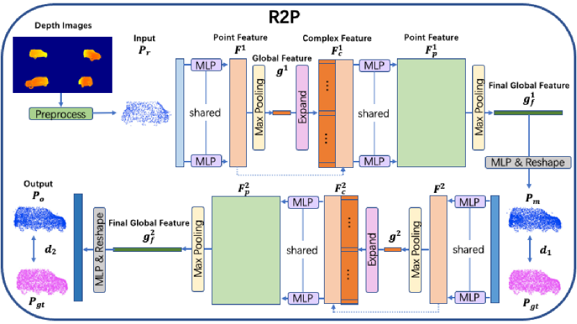
4.2 R2P Architecture
R2P’s input and output are 3D point clouds represented as matrices, where is the number of points in the point cloud, and each row represents the 3D Cartesian coordinate of a point. Note that the output point cloud generated from our network has a larger number of points than the input point cloud, i.e., our network can reconstruct a dense and smooth point cloud from a sparse one. R2P consists of two sequential processing blocks, and both blocks share the same encoder-decoder network design. The first block takes the raw input point cloud to produce an intermediate point cloud , and then the second block processes to generate the final output . In each block, the encoder takes its input point cloud and converts it to a high dimensional feature vector, and the decoder takes this feature vector and converts it to an intermediate or a final output point cloud.
Encoder. As shown in Fig. 1, in the first block, the encoder gets as input, and passes it to a shared multilayer perceptron (MLP) to extend every point in to a high dimensional feature vector and form the point feature matrix . This shared MLP is a network with two linear layers with BatchNorm and ReLU in between. Then, the encoder applies a point-wise maxpooling on and extracts a global feature vector . To produce a complete point cloud for an object, we need both local and global features, therefore, the encoder concatenates the global feature with each of the point features (of ) and form the complex feature matrix . Then another shared MLP is used to produce point feature matrix . Then, another point-wise maxpooling will perform on to extract the final global feature .
Decoder. Decoder takes the final global feature as input, and then passes it to a MLP, which consists of three fully-connected layers with ReLU in between. After this MLP, the final global feature is converted to vector (where is the number of points in ), and then reshaped to matrix which represents the point cloud .
As shown in Fig. 1, the second block’s design is similar to the first block. The encoder of the second block takes as input to produce a final global feature , and then the decoder generates the final output point cloud .
4.3 Loss Function
Due to the irregularity of point clouds, it is quite difficult to choose an effective loss function to indicate the difference between a generated point cloud and its corresponding ground truth point cloud. There are two popular metrics to evaluate the difference between two point clouds: Chamfer Distance (CD) [30] and Earth Mover’s Distance (EMD) [30]. CD calculates the average closest distance between two point clouds and . The symmetric version of CD is defined as:
| (1) |
EMD can find a bijection , which can minimize the average distance between each pair of corresponding points in two point clouds and . EMD is calculated as:
| (2) |
In our system, R2P generates the intermediate point cloud after its first encoder-decoder block, and then generates the final output point cloud after the second block. Hence, we design our loss function to evaluate both generated point clouds. That is, R2P’s loss function is defined as a weighted sum of the loss of the first block and the loss of the second block .
| (3) |
Both and can be either CD or EMD, or some weighted combination of them. is a hand-tuned parameter, and in our experiments, we find it performs well when set to 0.1. Note that unlike CD, EMD needs to find a bijection relationship between two point clouds, which is a optimization problem and hence computationally expensive, especially when the point clouds have large amounts of points. Moreover, this bijection also requires these two evaluated point clouds have the same number of points.
5 IMPLEMENTATION AND EXPERIMENTS
We implement our proposed R2P network and use it as the generator network of 3DRIMR system’s Stage 2. The system first generates 2D depth images from 3D radar intensity maps from multiple views of an object, and then passes these output depth images to R2P to produce a 3D point cloud of the object.
5.1 Datasets
We conduct experiments on a dataset including 5 different categories of objects, namely industrial robot arms, cars, chairs, desks, and L-shape boxes. This dataset consists of both synthesized data and real data collected from experiments. The input point clouds to R2P are the output depth images produced by 3DRIMR’s Stage 1. We follow a procedure that is similar to [20] to generate ground truth point clouds. In order to obtain enough amount of data required to train our deep neural network models, we modified HawkEye’s data synthesizer [6] to synthesize 3D radar intensity maps and 2D depth images from 3D CAD point-cloud models, with configurations matching TI’s mmWave radar sensor IWR6843ISK with DCA1000EVM [22], and Stereolabs’ ZED mini camera [19]. In our experiments and when generating synthesized data, we determine the space setup to capture the views of various objects in a 3D environment. Four pairs of mmWave radar sensors and depth camera sensors are placed at the centers of the four edges of a square area, pointing towards the center of the square area where objects are randomly placed.
5.2 Model Training and Testing
We use the 2D depth images generated in the Stage 1 of 3DRIMR to form a dataset of coarse and sparse input point clouds for the different categories of objects. Each input point cloud has points and an intermediate/final output point cloud has points. We train our proposed network model for each category independently. For each object category, we train the model based on pairs of point clouds for epochs with batch size . The learning rate for the first 100 epochs is and linearly decreases to 0 in the rest 100 epochs. Then we test the model using the remaining point clouds.
5.3 Evaluation Results
To the best of our knowledge, except for our previous work 3DRIMR, there are no other point cloud-based networks to reconstruct smooth, dense, and accurate point clouds from point clouds with many incorrect and inconsistent points, e.g., the union of multiple coarse point clouds which are converted from various 2D depth images of an object that are possibly inaccurate and inconsistent between themselves in terms of orientation and shape structure details. For example, a generated 2D depth image from radar data [5, 20] can possibly have a car’s left and right sides switched, or it can be shaped like a similar but different car with different shape details. Note that the existing works (e.g., [30]) on this subject usually do not have such strong inaccuracy assumption on their inputs except missing points. Nevertheless we compare our proposed architecture against five related baseline methods. They are popular point cloud-based generative models, mainly designed for the purposes of classification, segmentation, and point clouds completion, assuming input data is either sparse or there are missing points. To ensure fair comparison, we train all six models (including baselines and ours) based on the same training and testing datasets. These baseline methods include: (1) PointNet. It is introduced in [13]. We choose as the dimension of global feature of PointNet. The loss function is a combination of CD and EMD. (2) PointNet++. We use the same encoder architecture of PointNet++ [14] for classification with three Set Abstraction (SA) modules to get a 1024-dimension global feature, followed by a decoder consists of 3 fully-connected layers. The loss function is also a combination of CD and EMD. (3) PCN_CD. We use the same architecture of PCN[30], and set the grid size as 2. The number of points in the coarse and detailed output point clouds are 1024 and 4096 respectively. Note that in this method, both and are CD. (4) PCN_EMD. In this method, the architecture of the network is same as PCN_CD, but is EMD. (5) 3DRIMR. This is the only architecture designed for point clouds reconstruction from inaccurate input point clouds among the baselines. To ensure fair comparison, we use the combination of CD and EMD as its loss function.
Figure 2: Quantitative comparison on datasets of different objects using baseline methods and our method. Top: Chamfer Distance of the output point cloud and the ground truth. Bottom: Earth Mover’s Distance of the output point cloud and the ground truth.
We compare the performance of the two variants of our proposed R2P, labeled as R2P_CD (both and use CD) and R2P_EMD (both and use EMD), with the five baseline methods mentioned above in terms of CD and EMD. The results are shown in Fig. 2. We can see that except the case of robot arms, our methods always have the smallest CD or EMD loss among all the methods. Even for the robot arms, the performance of our methods are similar to the other five methods.
We further compare the results of all six methods by visually examining their output points clouds, and some of them are shown in Fig. 3. We can see that all the output point clouds are coarser than the ground truth point clouds and some of them lose many detailed shape characteristics. However, R2P_EMD can give the best shape reconstruction among all the methods, keeping most geometry characteristics. Especially for some small objects with fine shape details like chairs, only our method R2P_EMD can reconstruct an object with accurate shape.
| Input |
![[Uncaptioned image]](/html/2207.10690/assets/x2.png)
|
![[Uncaptioned image]](/html/2207.10690/assets/x3.png)
|
![[Uncaptioned image]](/html/2207.10690/assets/x4.png)
|
![[Uncaptioned image]](/html/2207.10690/assets/x5.png)
|
![[Uncaptioned image]](/html/2207.10690/assets/x6.png)
|
| PointNet++ |
![[Uncaptioned image]](/html/2207.10690/assets/x7.png)
|
![[Uncaptioned image]](/html/2207.10690/assets/x8.png)
|
![[Uncaptioned image]](/html/2207.10690/assets/x9.png)
|
![[Uncaptioned image]](/html/2207.10690/assets/x10.png)
|
![[Uncaptioned image]](/html/2207.10690/assets/x11.png)
|
| PCN_EMD |
![[Uncaptioned image]](/html/2207.10690/assets/x12.png)
|
![[Uncaptioned image]](/html/2207.10690/assets/x13.png)
|
![[Uncaptioned image]](/html/2207.10690/assets/x14.png)
|
![[Uncaptioned image]](/html/2207.10690/assets/x15.png)
|
![[Uncaptioned image]](/html/2207.10690/assets/x16.png)
|
| 3DRIMR |
![[Uncaptioned image]](/html/2207.10690/assets/x17.png)
|
![[Uncaptioned image]](/html/2207.10690/assets/x18.png)
|
![[Uncaptioned image]](/html/2207.10690/assets/x19.png)
|
![[Uncaptioned image]](/html/2207.10690/assets/x20.png)
|
![[Uncaptioned image]](/html/2207.10690/assets/x21.png)
|
| R2P_EMD |
![[Uncaptioned image]](/html/2207.10690/assets/x22.png)
|
![[Uncaptioned image]](/html/2207.10690/assets/x23.png)
|
![[Uncaptioned image]](/html/2207.10690/assets/x24.png)
|
![[Uncaptioned image]](/html/2207.10690/assets/x25.png)
|
![[Uncaptioned image]](/html/2207.10690/assets/x26.png)
|
| Ground Truth |
![[Uncaptioned image]](/html/2207.10690/assets/x27.png)
|
![[Uncaptioned image]](/html/2207.10690/assets/x28.png)
|
![[Uncaptioned image]](/html/2207.10690/assets/x29.png)
|
![[Uncaptioned image]](/html/2207.10690/assets/x30.png)
|
![[Uncaptioned image]](/html/2207.10690/assets/x31.png)
|
5.4 Performance of Different Loss Functions
Loss function plays a quite important role in model training. A well-designed loss function can not only speed up the training process, but also affect the performance of a deep learning model. On the other hand, a bad loss function may not converge even with a well-designed network model. Hence, we need to carefully design our loss function used when training our model. However, existing popular evaluation metrics to compare point clouds are CD and EMD, which can only evaluate the overall distance between a pair of point clouds but cannot effectively capture the similarity of their shapes.
To search for a good loss function for R2P, we conduct a series of experiments with different combinations of these two metrics. Except the loss functions used in training are different, all other settings are all the same for these experiments. The quantitative results are shown in Fig. 4. We can see that if we only use EMD in the loss function, which is L2 in the figure, the CD between output and ground truth point clouds will be large; and except in the box experiment, if we only use CD in the loss function, which is L1 in the figure, the EMD between output and ground truth point clouds will also be large. Hence, it makes sense to use the combination of CD and EMD, which is L3 in the figure, which gives both small CD and EMD. However, since calculating EMD is very expensive and time-consuming, using CD to evaluate intermediate output and EMD to evaluate final output , which is L4 in the figure, is also a good choice for the sake of efficiency.
Figure 4: Comparison of Different Loss Functions. L1: both and are CD; L2: both and are EMD; L3: both and are CD+EMD; L4: is CD and is EMD; L5: is EMD and is CD.
Remarks. (1) CD and EMD are important metrics to evaluate the difference between two point clouds. Generally speaking, small CD/EMD value means better reconstruction performance, and vice versa. However, due to the irregular format and lack-of-order information of point clouds, these two metrics are quite limited in terms of accurately indicating the shape difference between two point clouds, and hence cannot accurately describe the performance of a point cloud reconstruction method. Sometimes, a reconstructed point cloud may have larger CD or EMD though its shape is more similar to the ground truth point cloud. For example, as we can see in Fig. 2, the EMD of chair using 3DRIMR is smaller than R2P_EMD, but from Fig. 3, we can see that the output of R2P_EMD has more accurate shape of a chair. Hence, we should not focus only on the values of CD or EMD when evaluating a method’s reconstruction performance. (2) We have also conducted a series of experiments to explore different designs of our network architecture, e.g., using different pooling methods to extract global features, applying discriminators during the training process, and deeper network architecture with more layers. Nevertheless we find that the architecture shown in Fig. 1 performs the best and is efficient.
6 CONCLUSIONS AND FUTURE WORK
We have proposed R2P, a deep learning model that generates 3D objects in the form of smooth, dense, and highly accurate point clouds with fine geometry details. The inputs to R2P are directly converted from the 2D depth images that are generated from raw mmWave radar sensor data, and thus characterized by mutual inconsistency or errors in terms of orientation and shape. We have demonstrated with extensive experiments that R2P significantly outperforms existing methods such as PointNet/PointNet++, PCN, and 3DRIMR. In addition, we have shown the importance of loss function design in the training of models for reconstructing point clouds. For future work, we will further improve our design and test it with large scale experiments in more practical environments and with more object categories.
References
- [1] Dai, A., Ruizhongtai Qi, C., Nießner, M.: Shape completion using 3d-encoder-predictor cnns and shape synthesis. In: IEEE CVPR 2017
- [2] Fan, H., Su, H., Guibas, L.J.: A point set generation network for 3d object reconstruction from a single image. In: IEEE CVPR 2017
- [3] Fang, S., Nirjon, S.: Superrf: Enhanced 3d rf representation using stationary low-cost mmwave radar. In: Proc. of 2020 Intl Conf on EWSN
- [4] Ghasr, M.T., Horst, M.J., Dvorsky, M.R., Zoughi, R.: Wideband microwave camera for real-time 3-d imaging. IEEE Transactions on Antennas and Propagation 65(1), 258–268 (2016)
- [5] Guan, J., Madani, S., Jog, S., Gupta, S., Hassanieh, H.: Through fog high-resolution imaging using millimeter wave radar. In: IEEE CVPR 2020
- [6] Guan, J., Madani, S., Jog, S., Gupta, S., Hassanieh, H.: Hawkeye dataset and radar data synthesizer (2020), https://github.com/JaydenG1019/HawkEye-Data-Code
- [7] Ji, M., Gall, J., Zheng, H., Liu, Y., Fang, L.: Surfacenet: An end-to-end 3d neural network for multiview stereopsis. In: Proc. of the IEEE ICCV (2017)
- [8] Kar, A., Häne, C., Malik, J.: Learning a multi-view stereo machine. In: Proc. of the 31st Intl Conf on NeurIPS. pp. 364–375 (2017)
- [9] Kong, C., Lin, C.H., Lucey, S.: Using locally corresponding cad models for dense 3d reconstructions from a single image. In: IEEE CVPR 2017
- [10] Lu, C.X., Rosa, S., Zhao, P., Wang, B., Chen, C., Stankovic, J.A., Trigoni, N., Markham, A.: See through smoke: robust indoor mapping with low-cost mmwave radar. In: ACM MobiSys 2020
- [11] Mamandipoor, B., Malysa, G., Arbabian, A., Madhow, U., Noujeim, K.: 60 ghz synthetic aperture radar for short-range imaging: Theory and experiments. In: The 48th Asilomar Conf on Signals, Systems and Computers. IEEE (2014)
- [12] Paschalidou, D., Ulusoy, O., Schmitt, C., Van Gool, L., Geiger, A.: Raynet: Learning volumetric 3d reconstruction with ray potentials. In: IEEE CVPR 2018
- [13] Qi, C.R., Su, H., Mo, K., Guibas, L.J.: Pointnet: Deep learning on point sets for 3d classification and segmentation. arXiv preprint arXiv:1612.00593 (2016)
- [14] Qi, C.R., Yi, L., Su, H., Guibas, L.J.: Pointnet++: Deep hierarchical feature learning on point sets in a metric space. arXiv preprint arXiv:1706.02413 (2017)
- [15] National Academies of Sciences, E., Medicine, et al.: Airport Passenger Screening Using Millimeter Wave Machines: Compliance with Guidelines. National Academies Press (2018)
- [16] Sharma, A., Grau, O., Fritz, M.: Vconv-dae: Deep volumetric shape learning without object labels. In: ECCV. pp. 236–250. Springer (2016)
- [17] Sheen, D.M., McMakin, D.L., Hall, T.E.: Near field imaging at microwave and millimeter wave frequencies. In: 2007 IEEE/MTT-S International Microwave Symposium. pp. 1693–1696. IEEE (2007)
- [18] Smith, E.J., Meger, D.: Improved adversarial systems for 3d object generation and reconstruction. In: Conference on Robot Learning. pp. 87–96. PMLR (2017)
- [19] STEREOLABS: Zed mini datasheet 2019 rev1. https://cdn.stereolabs.com/assets/datasheets/zed-mini-camera-datasheet.pdf
- [20] Sun, Y., Huang, Z., Zhang, H., Cao, Z., Xu, D.: 3drimr: 3d reconstruction and imaging via mmwave radar based on deep learning. In: IEEE IPCCC (2021)
- [21] Sun, Y., Xu, D., Huang, Z., Zhang, H., Liang, X.: Lidaus: Localization of iot device via anchor uav slam. In: IEEE IPCCC 2020
- [22] Texas-Instruments: Dca1000evm. https://www.ti.com/tool/DCA1000EVM
- [23] Texas-Instruments: Introduction to mmwave radar sensing: Fmcw radars. https://training.ti.com/node/1139153
- [24] Texas-Instruments: Iwr6843isk, 2021. https://www.ti.com/tool/IWR6843ISK
- [25] Vandersmissen, B., Knudde, N., Jalalvand, A., Couckuyt, I., Bourdoux, A., De Neve, W., Dhaene, T.: Indoor person identification using a low-power fmcw radar. IEEE Transactions on GRSS 56(7), 3941–3952 (2018)
- [26] Wang, N., Zhang, Y., Li, Z., Fu, Y., Liu, W., Jiang, Y.G.: Pixel2mesh: Generating 3d mesh models from single rgb images. In: Proc. of the ECCV. pp. 52–67 (2018)
- [27] Wu, J., Zhang, C., Xue, T., Freeman, W.T., Tenenbaum, J.B.: Learning a probabilistic latent space of object shapes via 3d generative-adversarial modeling. arXiv preprint arXiv:1610.07584 (2016)
- [28] Yang, B., Wen, H., Wang, S., Clark, R., Markham, A., Trigoni, N.: 3d object reconstruction from a single depth view with adversarial learning. In: IEEE ICCV Workshops (2017)
- [29] Yang, X., Liu, J., Chen, Y., Guo, X., Xie, Y.: Mu-id: Multi-user identification through gaits using millimeter wave radios. In: IEEE INFOCOM 2020
- [30] Yuan, W., Khot, T., Held, D., Mertz, C., Hebert, M.: Pcn: Point completion network. In: 2018 Intl Conf on 3D Vision (3DV). pp. 728–737. IEEE (2018)