Downwash-aware Control Allocation for Over-actuated UAV Platforms
Abstract
Tracking position and orientation independently affords more agile maneuver for over-actuated multirotor Unmanned Aerial Vehicles while introducing undesired downwash effects; downwash flows generated by thrust generators may counteract others due to close proximity, which significantly threatens the stability of the platform. The complexity of modeling aerodynamic airflow challenges control algorithms from properly compensating for such a side effect. Leveraging the input redundancies in over-actuated UAVs, we tackle this issue with a novel control allocation framework that considers downwash effects and explores the entire allocation space for an optimal solution. This optimal solution avoids downwash effects while providing high thrust efficiency within the hardware constraints. To the best of our knowledge, ours is the first formal derivation to investigate the downwash effects on over-actuated UAVs. We verify our framework on different hardware configurations in both simulation and experiment.
I Introduction
Over-actuated UAV platforms with independent position and orientation tracking provide more agile maneuver compared with traditional multirotors. A straightforward realization is to tilt propellers [1, 2, 3, 4] and generate thrust forces in non-collinear directions. As a result, many platforms employ actively tiltable thrust generators [5, 6, 7], achieving higher thrust efficiency and enabling omnidirectional flights [3, 7].
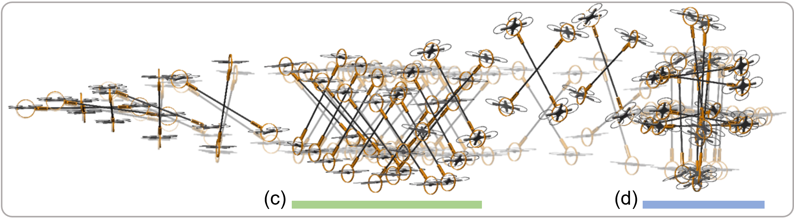
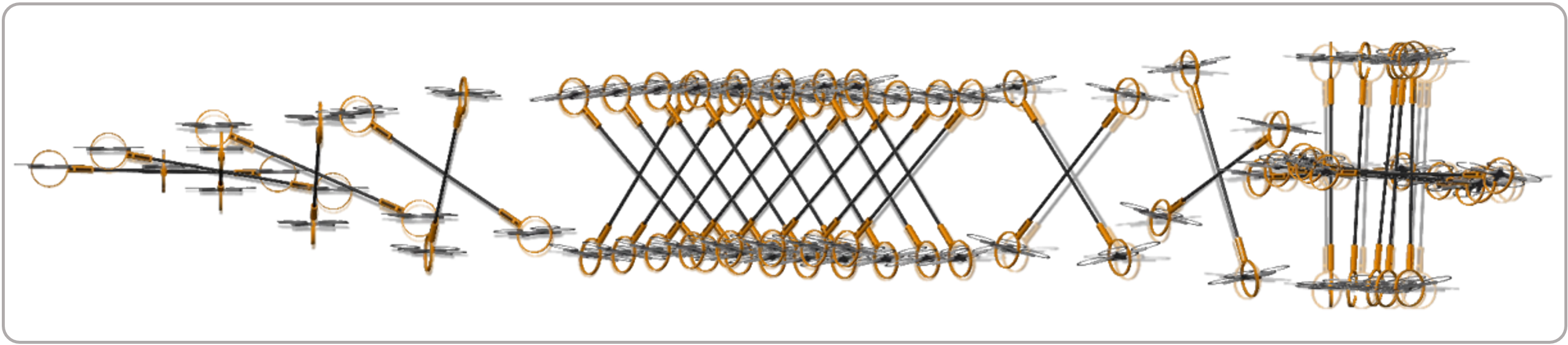
Adopting tiltable thrust generators unfortunately also introduces a common side effect—the downwash effect [8], which has been rarely studied in the context of over-actuated UAVs. This effect occurs when the airflow generated by one thrust generator/propeller passes through and interacts with the other(s), resulting in deteriorated trajectory tracking performance and lower trust efficiency; see Fig. 1 for an illustration. In the literature, the downwash effects are primarily treated by compensation [9, 10, 11, 12, 13] or as disturbances to be slowly attenuated by adding integrators into trajectory tracking controller [14, 7]. However, the former approach needs numerous experimental data to learn the platform-specific compensator, which cannot be generalized to other platforms. The latter solution is slow in response and hence has undesirable transitional behavior (e.g., obvious drop in the flow direction). Critically, both approaches only handle the downwash effect after it occurs and are inefficient in terms of energy, requiring extra thrusts to compensate.


In this paper, we tackle the downwash effects from a novel control allocation perspective for over-actuated UAVs with actively tiltable thrust generators. Due to input redundancy, there exists an infinite number of solutions to allocate desired force and torque commands to the low-level commands of thrust generators. This observation makes it possible to find a proper allocation such that no air flows would counteract with other thrust generators through a flight, thus reducing or even eliminating downwash effects beforehand.
We first incorporate the aerodynamics model for downwash effect analysis and investigate the relationship between downwash effect avoidance and thrust efficiency. Next, we extend our nullspace-based control allocation framework [14] by adding downwash avoidance constraints and a thrust efficiency index in the objective function. In simulation, we verify the proposed downwash-aware control allocation framework on different over-actuated UAV platforms. In experiment, we build physical platforms that combine commercial quadcopters with passive gimbal joints as 3- Degree of Freedom (DoF) thrust generators and verify the proposed framework. Collectively, we demonstrate that the proposed framework can fully explore the entire allocation space and find the optimal allocation solution that avoids downwash effects and maintains a high thrust efficiency.
I-A Related Work
Downwash effects have recently drawn an increasing attention, primarily on computational models of two UAVs [15, 16, 17] to achieve better motion cooperation [18, 19]. Downwash effects for multi-UAV systems are more challenging to handle. The most straightforward solution is to keep enough safety distance among UAVs to avoid the interference introduced by downwash effects [20]. Learning-based method has also been proposed to compensate for the downwash effects among multirobot swarm [21, 22]. Different from the above work in multi-agent scenarios, we study over-actuated UAV platforms, wherein several thrust generators are physically connected to a common frame. By developing a centralized control allocation framework, our framework avoids the downwash effects by exploiting input redundancy when generating low-level control commands of thrust generators.
Commanding each actuator given the desired total wrench of the platform, the control allocation of over-actuated UAV platforms is a constrained nonlinear optimization problem and is generally difficult to solve with high efficiency. Prior work leverages gradient-descent [23], force decomposition [24], iterative approach [25], separation method [26], and linear approximation [27] to reduce the computational complexity. However, none can incorporate input constraints while providing exact solutions with satisfactory efficiency. This limitation was first solved by Su et al. [14], who devised a nullspace-based control allocation framework; henceforth, we referred to this framework as the conventional allocation framework. This paper extends this framework by incorporating a downwash effect avoidance constraint and adding a thrust efficiency index to the objective function. As a result, various UAV platforms with 3-DoF thrust generators [3, 7, 1, 2, 28, 4] can achieve any arbitrary attitude without downwash effects while maintaining high thrust efficiency along the entire possible configuration space.
I-B Overview
We organize the remainder of the paper as follows. Section II presents the dynamics model of the UAV system with downwash effect modeling. We analyze downwash effects and study the relation between downwash effect avoidance and thrust efficiency in Section III. Section IV describes the hierarchical control structure and the proposed downwash-aware allocation framework. Section V and Section VI show the simulation and experiment results with comprehensive evaluations. Finally, we conclude the paper in Section VII.
II Platform Model with Aerodynamics
The over-actuated UAV system discussed in this paper adopts regular quadcopters with 2-DoF passive gimbal mechanism, serving as 3-DoF thrust generators [7]. This system has demonstrated various configurations depending on the number of thrust generators and mainframe design [29], and its dynamics is mathematically equivalent to some seminal platforms [3, 4, 7, 2].
II-A System Frames and Configuration
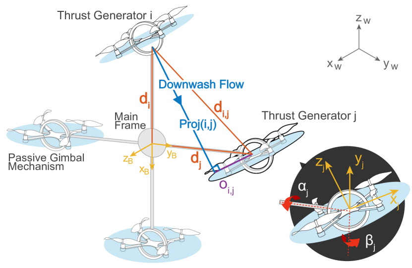
Fig. 2 outlines the system frames and configurations. Let denote the world coordinate frame and attach the platform frame to the geometric center of the UAV platform. We define the central position of the main frame as , the attitude in the roll-pitch-yaw convention as , and the platform angular velocity in as . Actuator frames s are attached to the geometric center of the th 3-DoF thrust generator.
II-B Platform Dynamics
The dynamics model of this over-actuated UAV platform can be described as in Yu et al. [7].
| (1) |
where the translational dynamics are expressed in the world frame , whereas the rotational dynamics are described in body-fix frame . and are the total mass and inertia matrix of the platform, respectively. and are the linear and angular acceleration of the central frame, respectively. is the acceleration due to gravity, is the gravity torque due to the displacement of its center of mass (CoM) from the geometric center [3], , and
| (2) |
where , , and denote the magnitude of thrust, tilting, and twisting angles of the th thrust generator. is the number of thrust generators, the distance vector from ’s center to each , and the external force/torque input, assumed to be caused by downwash effects.
II-C Downwash Effect Modeling
As elaborated by Khan et al. [15], for the zone of flow establishment (ZFE), the velocity field of a quadcopter follows a Gaussian distribution,
| (3) |
with
| (4) |
where and are the vertical and radial separations, respectively. is the viscosity constant. , , and are the position, contracted radius, and induced velocity of the efflux plane, respectively. is the radial location of the maximum velocity at each cross-section. and are two parameters, which can be experimentally determined.
With the model introduced in Jain et al. [17], the thrust change caused by oncoming flows for every propeller is estimated:
| (5) |
where is the thrust generated by the th propeller of th quadcopter module, defined by:
| (6) |
where is the rotational speed, and are the vertical and radial separations between th quadcopter’s th propeller and th quadcopter’s downwash flow, and is the thrust decay coefficient, obtained experimentally.
We calculate the th quadcopter’s thrust and torque disturbance caused by the downwash effects as in Ruan et al. [30]:
| (7) |
where affects the low-level attitude control of th quadcopter. are the torque outputs in . is a constant defined as , where is the distance of each propeller to the quadcopter center. is a constant defined as , where is the propeller drag constant, and the standard propeller thrust constant. mainly influences the high-level control as external force, and we can have
| (8) |
Section VI adopts this downwash effect model for simulation with the parameters acquired from experimental data.
III Downwash Effect Analysis
III-A Downwash Constraint Derivation
As shown in Fig. 2, the radial distance between th quadcopter’s downwash flow and th quadcopter’s center is defined as , which be calculated by
| (9) | ||||
| (10) | ||||
| (11) |
where dot refers to the dot product of two vectors. By having , is a function of and . If we build a vector by stacking , we can calculate a minimum distance vector to constraint . As a result, the downwash effect avoidance can be achieved by requiring
| (12) |
Of note, as shown in Algorithm 1, we need only this constraint when the downwash flows go through other quadcopters in the positive direction. As this inequality constraint is highly nonlinear, we approximately include this constraint into the nullspace-based allocation framework by first-order linearization, to be detailed in Section IV-B.
III-B Downwash Effect Avoidance and Thrust Efficiency
The “thrust efficiency index” was defined by Ryll et al. [31] to quantify wasted internal forces in over-actuated multirotor systems. Formally, it is defined as
| (13) | ||||
where is a configuration-dependent ratio between the sum of vectored thrusts and the sum of total thrust magnitudes.
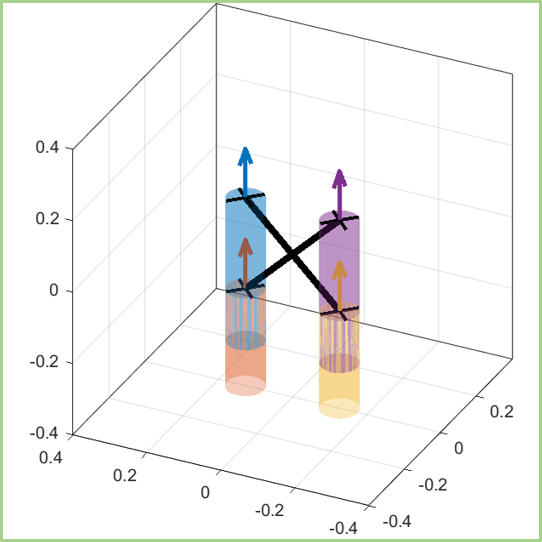
We study the relation between downwash avoidance and thrust efficiency for three different over-actuated UAV platforms with four, five, and six 3-DoF thrust generators; Fig. 3 summarizes the results. When the platforms fly vertically (see Figs. 3(a), 3(d) and 3(g)), downwash effects still appear as most prior allocation frameworks [14, 7] if we only try to maintain maximum thrust efficiency (). By exploring the entire configuration space, other feasible configurations might both avoid downwash effects and maintain high thrust efficiency (see Figs. 3(c), 3(f) and 3(i)). This finding motivates us to propose a new allocation framework that efficiently finds such a configuration for the over-actuated UAV platforms.
In Eq. 13, the numerator of is provided by wrench command of tracking controller, which can be treated as a constant value in allocation. To include thrust efficiency index into the objective function of the nullspace-based allocation framework, we choose to minimize the denominator of Eq. 13 (); please refer to Section IV-B for details.
IV Downwash-aware Controller Design
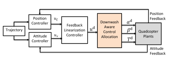
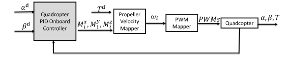
The overall controller has a hierarchical architecture, shown in Fig. 4. The high-level trajectory tracking controller (see Fig. 4(a)) (i) calculates the desired force/torque command (6-DoF wrench command) for the entire platform, and (ii) allocates the force/torque command to tilting angle , twisting angle , and thrust of each 3-DoF thrust generator. The low-level controller (see Fig. 4(b)) of each quadcopter (i) regulates the individual attitude to the desired values and (ii) provides the required thrust force.
IV-A High-level Control
Without downwash effects, the dynamics equation (i.e., Eq. 1) can be rewritten following Su et al. [32]
| (14) |
We design the feedback-linearization controller as
| (15) |
where the superscript indicates the desired values. Our above controller design transfers platform dynamics expressed by Eq. 14 into a simple double integrator [33],
| (16) |
Two virtual inputs and can be designed with translational and rotational errors to track predefined reference position and attitude trajectory. We close this control loop by an LQR controller that considers communication delay and improves system robustness [33, 34].
IV-B Downwash-aware Control Allocation
The nullspace-based control allocation framework of over-actuated UAVs has been proposed in Su et al. [14] to solve , , and from while maintaining defined input constraints. To avoid downwash effects and maintain high thrust efficiency, we modify the framework and reformulate the Quadratic Programming (QP) problem as described below.
An intermediate variable is defined as
| (17) |
where
| (18) |
With , we can transform the nonlinear allocation problem to a linear one,
| (19) |
where is a constant allocation matrix with full row rank. Therefore, can be solved from with a general solution form,
| (20) |
where is the nullspace of , and is an arbitrary vector.
As discussed in Su et al. [14], Eq. 20 is linearized with the first-order Taylor expansion and relaxed with slack variable ,
| (21) |
where is defined as , is the value of a variable at last time step, and is the difference w.r.t. the previous time step of a variable.
Similarly, the downwash avoidance constraint (see Eq. 12) can be approximated by another linear equation as a linear inequality constraint,
| (22) |
The physical constraints of the platform are designed as
| (23) |
| (24) |
The objective function is designed as
| (25) |
where are three positive semi-definite weighting matrices. As introduced in Section III-B, the thrust efficiency index is included as , with
| (26) |
Then we have
| (27) |
where is the scaling factor. Of note, is a constant, thus removed from the objective function.
After solving this optimization problem Eqs. 21, 22, 23, 24 and 25, we can approximately calculate the desired for next step with discrete integration,
| (28) |
To eliminate the approximation errors, we utilize nullspace projection with
| (29) | ||||
| (30) |
Finally, with exact solution , low-level commands , , and can be recovered with inverse kinematics:
| (31) | ||||
| (32) | ||||
| (33) |
IV-C Low-level Control
The joint angles of each quadcopter module are controlled by separate PID controllers based on the error dynamics:
| (34) |
where and are constant PID gains, and
| (35) |
are error terms with joint angle feedback , from onboard IMU. The related torque commands are determined by
| (36) |
For each quadcopter module, with Eqs. 7 and 6, the angular velocity of each propeller can be calculated, later converted to the PWM signal to drive the motor.
V Simulation and Experiment Setups
V-A Simulation Setup
Before conducting physical experiments, we develop a simulation platform in Matlab Simulink/Simscape to evaluate and characterize the proposed downwash-aware control allocation framework. In addition to the UAV’s physical parameters obtained from system identification, the dynamics of propeller motors and saturation, control frequencies, measurement noise, and communication noise and delays, the simulator also incorporates the downwash aerodynamics model introduced in Section II-C based on experimental data.
The proposed allocation framework was verified on two over-actuated platforms with four and six 3-DoF thrust generators, respectively. Table I summarizes the physical and software properties acquired from the physical system used in simulation, where and refer to the mass and inertia matrix of the mainframe, and and refer to the mass and inertia matrix of each 3-DoF thrust generator.
| Parameter | Four | Six |
| Communication delay/sec | ||
| Remote PC control rate/ | ||
| Onboard control rate/ |
V-B Experiment Setup
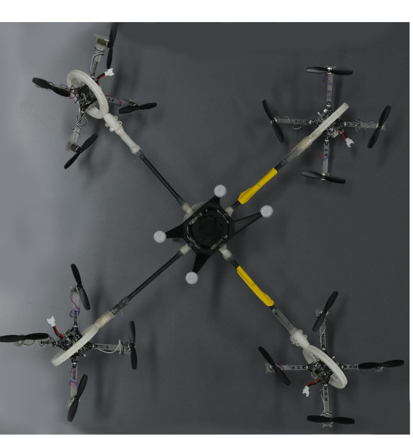
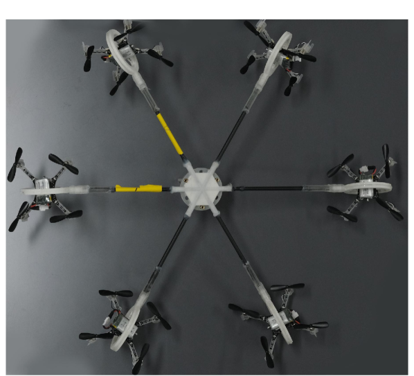
As shown in Fig. 5, the quadcopters are connected to the central frame by 2-DoF passive gimbal mechanism, which have no rotation-angle limitations, thus can be utilized as 3-DoF thrust generators. We use Crazyflie 2.1 as the quadcopter module. The weight of Crazyflie 2.1 is with a maximum total payload. For the platform with four 3-DoF thrust generators, we upgraded the motors, propellers, and batteries of the Crazyflie for larger thrust force.
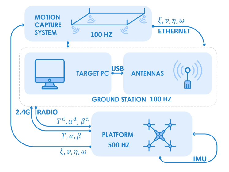
In the experiment, we use the Noitom motion capture system to measure the position and attitude of the central frame. The main controller runs on a remote PC, which communicates with the motion capture system through Ethernet. The main controller calculates the desired thrust , tilting angles , and twisting angles for all quadcopter modules. The communication between the remote PC and each quadcopter is achieved by Crazy Radio PA antennas (2.4G ). Each quadcopter is embedded with an onboard IMU module, estimating the rotation angle given the attitude of central frame . Meanwhile, the onboard controller regulates the tilting and twisting angles to desired values and provides the required thrust. The measurement rate of the motion capture system, the remote PC controller, and the data communication with each quadcopter are all set to 100 . The quadcopter’s onboard controller is set to 500 for fast low-level response. Fig. 6 shows the software architecture.
VI Simulation and Experiment Results
VI-A Simulation Results
Fig. 7 summarizes the simulation results of two over-actuated UAV platforms with the proposed downwash effect model introduced in Section II-C. For the platform that has four 3-DoF thrust generators, a reference attitude trajectory is designed where the downwash effects occur twice (Fig. 7(a)). As we can see, the downwash effect first appears at about 9s, when the platform is rotated at 90 degree along the axis ; and , as well as and , aligned vertically (two pairs of downwash effect). With conventional allocation framework, the downwash flows significantly influence the control of the platform; we noticed a drop in Z axis with about , and the control performance of other 5-DoF is also deteriorated (Fig. 7(b)). Later, another downwash effect appears at about ( and aligned vertically), which finally makes the platform unstable. Using the proposed the downwash-aware allocation framework, the platform tracks the reference trajectory stably (Figs. 7(f) and 7(g)) and maintain a high thrust efficiency (Fig. 7(h)). Please see also Fig. 1 for better visualization.
For the platform that has six 3-DoF thrust generators, a 90 degree pitch reference trajectory (Fig. 7(k)) is utilized, and three pairs of downwash effects happen at the final attitude. With the conventional allocation framework, although the platform is still stable, we noticed a drop in Z-axis with more than to compensate for position control (Fig. 7(l)). Further, as we can see in Fig. 7(m), this framework needs more thrusts to compensate for the downwash aerodynamics, inefficient in terms of energy. With our proposed downwash-aware allocation framework, the control in the Z-axis is maintained, and the thrust is not increased by much for downwash avoidance. In summary, by exploring the entire allocation space, the downwash effects are avoided, and the high thrust efficiency is maintained.
VI-B Experiment Results

We conducted experiments on the over-actuated UAV platform that has four 3-DoF thrust generators to compare the conventional allocation framework and our proposed downwash-aware allocation framework; see Fig. 8. Using the conventional allocation framework, the platform is controlled to track a 90 degree pitch reference trajectory (Fig. 8(a)), where a pair of downwash effects appear, and an obvious drop in the Z-axis is noticed (Fig. 8(b)). Although the uniformly high thrust efficiency is maintained by deploying all the thrusts in the same direction, this framework requires more thrust forces to slowly compensate downwash effects with the integrator of position controller (Fig. 8(c)). Moreover, the stability of the platform is influenced by more oscillations.
Using the proposed downwash-aware allocation framework, the platform avoids the downwash effects by deploying the proper thrust forces and maintains a high thrust efficiency (Figs. 8(i), 8(j) and 8(h)). Therefore, the position and attitude tracking control performance is guaranteed along whole trajectory (Figs. 8(g) and 8(f)). Fig. 8(k) shows keyframes of the experiment.
VI-C Discussion
The minimum downwash avoid distance in Algorithm 1 has to be experimentally decided for different platforms. means the downwash avoidance is not activated. Large may result in no feasible solution to the downwash-aware allocation problem. Despite that small cannot fully avoid downwash flow, it can still improve the control performance to some extent. We chose in the experiment.
VII Conclusion
We presented the downwash-aware control allocation framework of over-actuated UAVs, which makes synergy of downwash effect avoidance and thrust efficiency maintenance. The downwash avoidance constraint and thrust efficiency index were derived and incorporated into the nullspace-based allocation framework. In simulation, the proposed downwash-aware and original nullspace-based allocation frameworks were studied and compared on two different over-actuated platforms. These frameworks were further implemented on our customized UAV platforms in experiment for demonstration. Both simulation and experiment verified that our proposed framework fully explores the allocation space and finds the desired allocation solution that could both avoid downwash effect and maintain high thrust efficiency, significantly improving the control performance.
Acknowledgement
The authors thank Dr. Tengyu Liu, Nan Jiang, Zihang Zhao, Hao Liang, Zeyu Zhang, Zhen Chen, Yifei Dong at BIGAI for discussions and help on hardware design, motion capture system, and figures; Dr. Pengkang Yu at UCLA for his help on control framework of Crazyflie. In particular, Yao Su wants to thank the love, patience, and care from his girlfriend Mengmeng, and wishes the best of her surgery.
References
- [1] T. Anzai, M. Zhao, X. Chen, F. Shi, K. Kawasaki, K. Okada, and M. Inaba, “Multilinked multirotor with internal communication system for multiple objects transportation based on form optimization method,” in International Conference on Intelligent Robots and Systems (IROS), 2017.
- [2] B. Li, L. Ma, D. Huang, and Y. Sun, “A flexibly assembled and maneuverable reconfigurable modular multi-rotor aerial vehicle,” IEEE/ASME Transactions on Mechatronics (TMECH), 2021.
- [3] M. J. Gerber and T.-C. Tsao, “Twisting and tilting rotors for high-efficiency, thrust-vectored quadrotors,” Journal of Mechanisms and Robotics, vol. 10, no. 6, p. 061013, 2018.
- [4] A. F. Şenkul and E. Altuğ, “System design of a novel tilt-roll rotor quadrotor uav,” Journal of Intelligent & Robotic Systems, vol. 84, no. 1, pp. 575–599, 2016.
- [5] H.-N. Nguyen, S. Park, J. Park, and D. Lee, “A novel robotic platform for aerial manipulation using quadrotors as rotating thrust generators,” Transactions on Robotics (T-RO), vol. 34, no. 2, pp. 353–369, 2018.
- [6] C. Pi, L. Ruan, P. Yu, Y. Su, S. Cheng, and T. Tsao, “A simple six degree-of-freedom aerial vehicle built on quadcopters,” in Proceedings of IEEE Conference on Control Technology Applications (CCTA), 2021.
- [7] P. Yu, Y. Su, M. J. Gerber, L. Ruan, and T.-C. Tsao, “An over-actuated multi-rotor aerial vehicle with unconstrained attitude angles and high thrust efficiencies,” IEEE Robotics and Automation Letters (RA-L), vol. 6, no. 4, pp. 6828–6835, 2021.
- [8] N. Michael, D. Mellinger, Q. Lindsey, and V. Kumar, “The grasp multiple micro-uav testbed,” IEEE Robotics and Automation Magazine (RA-M), vol. 17, no. 3, pp. 56–65, 2010.
- [9] Y. Su, L. Ruan, P. Yu, C.-H. Pi, M. J. Gerber, and T.-C. Tsao, “A fast and efficient attitude control algorithm of a tilt-rotor aerial platform using inputs redundancies,” IEEE Robotics and Automation Letters (RA-L), vol. 7, no. 2, pp. 1214–1221, 2021.
- [10] H. Lee, M. Jeong, C. Kim, H. Lim, C. Park, S. Hwang, and H. Myung, “Low-level pose control of tilting multirotor for wall perching tasks using reinforcement learning,” in International Conference on Intelligent Robots and Systems (IROS), 2021.
- [11] W. Zhang, M. Brunner, L. Ott, M. Kamel, R. Siegwart, and J. Nieto, “Learning dynamics for improving control of overactuated flying systems,” IEEE Robotics and Automation Letters (RA-L), vol. 5, no. 4, pp. 5283–5290, 2020.
- [12] R. Yang, L. Zheng, J. Pan, and H. Cheng, “Learning-based predictive path following control for nonlinear systems under uncertain disturbances,” IEEE Robotics and Automation Letters (RA-L), vol. 6, no. 2, pp. 2854–2861, 2021.
- [13] P. Yu, An Over-Actuated Multi-Rotor Aerial Platform and Iterative Learning Control Applications. PhD thesis, University of California, Los Angeles, 2022.
- [14] Y. Su, P. Yu, M. Gerber, L. Ruan, and T.-C. Tsao, “Nullspace-based control allocation of overactuated uav platforms,” IEEE Robotics and Automation Letters (RA-L), vol. 6, no. 4, pp. 8094–8101, 2021.
- [15] W. Khan, M. Nahon, and R. Caverly, “Propeller slipstream model for small unmanned aerial vehicles,” in AIAA modeling and simulation technologies (MST) conference, 2013.
- [16] Y. Zheng, S. Yang, X. Liu, J. Wang, T. Norton, J. Chen, and Y. Tan, “The computational fluid dynamic modeling of downwash flow field for a six-rotor uav,” Frontiers of Agricultural Science and Engineering, vol. 5, no. 2, pp. 159–167, 2018.
- [17] K. P. Jain, T. Fortmuller, J. Byun, S. A. Mäkiharju, and M. W. Mueller, “Modeling of aerodynamic disturbances for proximity flight of multirotors,” in International Conference on Unmanned Aircraft Systems (ICUAS), 2019.
- [18] R. Miyazaki, R. Jiang, H. Paul, K. Ono, and K. Shimonomura, “Airborne docking for multi-rotor aerial manipulations,” in International Conference on Intelligent Robots and Systems (IROS), 2018.
- [19] J. L. Brinkman, B. Davis, and C. E. Johnson, “Post-movement stabilization time for the downwash region of a 6-rotor uav for remote gas monitoring,” Heliyon, vol. 6, no. 9, p. e04994, 2020.
- [20] J. A. Preiss, W. Hönig, N. Ayanian, and G. S. Sukhatme, “Downwash-aware trajectory planning for large quadrotor teams,” in International Conference on Intelligent Robots and Systems (IROS), 2017.
- [21] G. Shi, W. Hönig, Y. Yue, and S.-J. Chung, “Neural-swarm: Decentralized close-proximity multirotor control using learned interactions,” in International Conference on Robotics and Automation (ICRA), 2020.
- [22] G. Shi, W. Hönig, X. Shi, Y. Yue, and S.-J. Chung, “Neural-swarm2: Planning and control of heterogeneous multirotor swarms using learned interactions,” Transactions on Robotics (T-RO), 2021.
- [23] M. Ryll, H. H. Bülthoff, and P. R. Giordano, “A novel overactuated quadrotor unmanned aerial vehicle: Modeling, control, and experimental validation,” IEEE Transactions on Control Systems Technology, vol. 23, no. 2, pp. 540–556, 2014.
- [24] M. Kamel, S. Verling, O. Elkhatib, C. Sprecher, P. Wulkop, Z. Taylor, R. Siegwart, and I. Gilitschenski, “The voliro omniorientational hexacopter: An agile and maneuverable tiltable-rotor aerial vehicle,” IEEE Robotics and Automation Magazine (RA-M), vol. 25, no. 4, pp. 34–44, 2018.
- [25] M. Zhao, K. Okada, and M. Inaba, “Enhanced modeling and control for multilinked aerial robot with two dof force vectoring apparatus,” IEEE Robotics and Automation Letters (RA-L), vol. 6, no. 1, pp. 135–142, 2020.
- [26] M. Santos, L. Honório, A. Moreira, M. Silva, and V. Vidal, “Fast real-time control allocation applied to over-actuated quadrotor tilt-rotor,” Journal of Intelligent & Robotic Systems, vol. 102, no. 3, pp. 1–20, 2021.
- [27] T. A. Johansen, T. I. Fossen, and S. P. Berge, “Constrained nonlinear control allocation with singularity avoidance using sequential quadratic programming,” IEEE Transactions on Control Systems Technology, vol. 12, no. 1, pp. 211–216, 2004.
- [28] M. A. da Silva Ferreira, M. F. T. Begazo, G. C. Lopes, A. F. de Oliveira, E. L. Colombini, and A. da Silva Simões, “Drone reconfigurable architecture (dra): A multipurpose modular architecture for unmanned aerial vehicles (uavs),” Journal of Intelligent & Robotic Systems, vol. 99, pp. 517–534, 2020.
- [29] M. Wang, Y. Su, H. Liu, and Y. Xu, “Walkingbot: Modular interactive legged robot with automated structure sensing and motion planning,” in International Symposium on Robot and Human Interactive Communication (RO-MAN), 2020.
- [30] L. Ruan, Independent position and attitude control on multirotor aerial platforms. PhD thesis, University of California, Los Angeles, 2020.
- [31] M. Ryll, D. Bicego, and A. Franchi, “Modeling and control of fast-hex: A fully-actuated by synchronized-tilting hexarotor,” in International Conference on Intelligent Robots and Systems (IROS), 2016.
- [32] Y. Su, Compensation and Control Allocation with Input Saturation Limits and Rotor Faults for Multi-Rotor Copters with Redundant Actuations. PhD thesis, University of California, Los Angeles, 2021.
- [33] L. Ruan, C. Pi, Y. Su, P. Yu, S. Cheng, and T. Tsao, “Control and experiments of a novel tiltable-rotor aerial platform comprising quadcopters and passive hinges,” Mechatronics (submitted), 2022.
- [34] Y. Su, P. Yu, M. Gerber, L. Ruan, and T. Tsao, “Fault-tolerant control of overactuated multirotor uav platform under propeller failure,” IEEE Transactions on Control Systems Technology (submitted), 2022.