Boosting thermal conductivity by surface plasmon polaritons propagating along a thin Ti film
Abstract
We experimentally demonstrate a boosted in-plane thermal conduction by surface plasmon polaritons (SPPs) propagating along a thin Ti film on a glass substrate. Owing to a lossy nature of metal, SPPs can propagate over centimeter-scale distance even with a supported metal film, and resulting ballistic heat conduction can be quantitatively validated. Further, for a 100-nm-thick Ti film on glass substrate, a significant enhancement of in-plane thermal conductivity compared to bulk value () is experimentally shown. This study will provide a new avenue to employ SPPs for heat dissipation along a supported thin film, which can be readily applied to mitigate hot-spot issues in microelectronics.
I
Nanoscale thin films cause a classical size effect on thermal conductivity as their thicknesses become smaller than the mean free paths of phonons or electrons [1, 2].Decreased thermal conductivity impedes heat spreading from hot spots within the devices, deteriorating their performance. As a solution, surface electromagnetic waves have been spotlighted as auxiliary heat carriers due to their orders longer propagation length than primary heat carriers (i.e., phonons and electrons) [3, 4, 5, 6, 7, 8, 9], which can compensate for the size effect of film thermal conductivity.
Surface phonon polaritons (SPhPs), surface electromagnetic waves coupled with optical phonons, can carry heat and thus enhance the dielectric film thermal conductivity [10, 11, 12]. Over the past few decades, thermal transport via SPhPs has been thoroughly studied for suspended dielectric membranes [5, 6, 9, 13]. Chen et al. proposed first that SPhPs can enhance the in-plane thermal conductivity of a 40-nm-thick-SiO2-suspended-membrane by more than 100% of its bulk value [5]. SPhPs have an orders of magnitude longer propagation length () than acoustic phonons in a SiO2 membrane [14, 7]. Subsequently, the SPhP thermal conductivity of a suspended dielectric membrane was experimentally demonstrated [9, 13]. Tranchant et al. measured the in-plane thermal conductivity of the suspended SiO2 membrane with respect to its thickness and width by using the 3 method [9]. Due to relatively large measurement errors, their results could not conclusively reveal the significant enhancement of SiO2 membrane thermal conductivity. Later, Wu et al. used the micro time-domain thermoreflectance method to observe the SPhP thermal conductivity of suspended SiN membranes depending on their temperature [13]. However, their results could not reveal a strong link between the propagation lengths of the SPhPs and the resulting thermal conductivity. Such limitations in early measurements are mainly due to the limitations of the fabrication of nanoscale suspended membranes with large surface area. Although a supported thin film structure is preferred in terms of both experimental validation and real-world application, for a polar dielectric thin film on a substrate, a surface electromagnetic wave can only be supported when a film thickness is greater than the cutoff thickness [6, 15], which causes significantly reduced thermal conduction by surface waves [6, 16]. Consequently, there has been no experimental demonstration of surface-wave-enhanced thermal conductivity on a supported structure so far.
Surface plasmon polartions (SPPs) are other forms of surface electromagnetic waves coupled to free electrons in metals, which can be thermally excited and function as heat carriers. Thermally excited SPPs in lossy metals or heavily-doped semiconductors exist in broad spectral regions and have been successfully employed to tune the near-field thermal radiation [17, 18, 19, 20, 21, 22, 23]. In fact, SPPs supported at a lossy metal/dielectric interface can have propagation lengths of several millimeters or more in the mid-infrared regime [8]. Furthermore, long-range SPPs can propagate over centimeter-scale distances in a ‘thin’ metal film [24]. Therefore, SPPs supported in the thin lossy metal film can lead to a significant enhancement of its thermal conductivity. In this work, we experimentally demonstrate for the first time that SPPs on a thin lossy metallic film can also be exploited to enhance its in-plane thermal conductivity even in a supported configuration. We deposit a thin Ti film on a glass substrate with circular patterns, varying its radius. The size effect of SPP-enhanced thermal conductivity is clearly demonstrated by limiting the long propagation of SPPs (a few centimeters) to a smaller radius. Also, the effect of Ti-film thickness is quantitatively analyzed by varying its thickness (e.g., 100 nm, 300 nm, or 1000 nm). The measured in-plane thermal conductivity of Ti films is compared with a theoretical prediction based on the Boltzmann transport equation to reveal the relationship between the SPP propagation length and thermal conductivity.
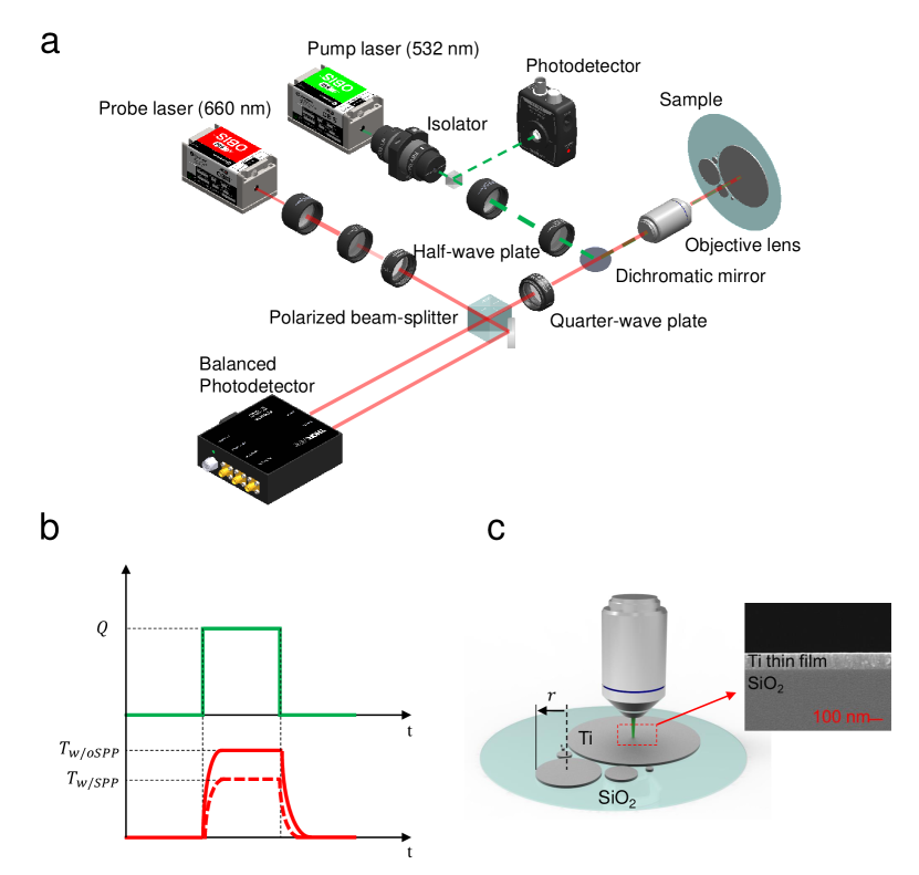
We employed a steady-state thermoreflectance method (SSTR) [25] to measure the in-plane thermal conductivity of Ti films, as shown in Fig. 1a. Section 1 of Supplemental Material describes our SSTR setup and validation. The SSTR is a variation of the frequency-domain thermoreflectance method (FDTR), which heats the sample near steady-state by reducing the modulation frequency of the pump laser. Due to its long thermal penetration depth, the SSTR has good measurement sensitivity on the in-plane thermal conductivity of thin films (Fig. S2). The in-plane thermal conductivity of thin films can then be obtained by fitting the measured surface temperature of the heated spot with the theoretical prediction derived from the two-dimensional (2-D) heat diffusion model [26](Section 3 of Supplemental Material). We used the Ti film as a transducer considering its optical property [27]; that is, there is no additional metal layer deposited for the measurement. Because the thermal conductivity of a glass substrate (i.e., W/mK; Table S2) is much lower than that of Ti (10 W/mK), heat is mainly transferred through the Ti film like a suspended structure, increasing the measurement sensitivity of the in-plane thermal conductivity of the Ti film. Since the SSTR cannot distinguish the SPP-enhanced thermal conductivity from the diffusive electronic counterpart of Ti film, we experimentally investigated the thermal conductivity via SPPs with the SPP-induced temperature drop of the Ti film by comparing the temperature rise of the Ti film surface with and without SPP excitations under the same amount of laser irradiation, as illustrated in Fig. 1b.
For measurements, a thin Ti film was first e-beam deposited on a glass substrate with various thicknesses and then circularly patterned by lift-off process. The Ti films were patterned with radius ranging from 200 m to 28 mm. As shown in the inset of Fig. 1c, the Ti films were uniformly deposited. Due to boundary scattering effect resulting from the radius of Ti-film patterns, the effective propagation length () of SPPs was determined by Matthiessen’s rule (i.e., , where is the radius of the Ti-film pattern). Also, the spectral reflectance of the Ti film at wavelengths from 500 nm to 700 nm, which includes the pumping wavelength (i.e., nm) and the probing wavelength (i.e., nm), was measured with a UV-VIS spectrometer (UV-3600 Plus, Shimadzu) and agreed excellently with the theoretical prediction derived from the optical property of Ti using the Drude model [28](see Fig. S3). Thus, the Drude model is used when calculating the dispersion of SPPs for a thin Ti film deposited on a glass substrate.
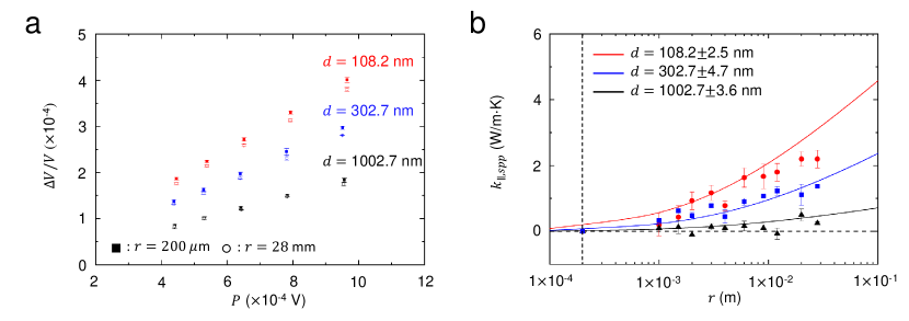
Figure 2a shows the probe reflectance response () measured by the balanced photodetector for Ti films with different thicknesses and radii. The probe reflectance response of the Ti film with mm is noticeably lower than that of the Ti film with m at a given thickness . For example, for 108.2-nm-Ti film is 6.5% lower when mm than m. We believe that this difference in normalized probe reflectance with respect to the sample radius is caused by SPPs propagating along the Ti film for several millimeters.
Considering that the probe reflectance response is proportional to the surface temperature change , and the absorbed heat is proportional to the pump laser photodetector signal , the proportionality constant can be defined as [25]
| (1) |
The thermal conductivity can be fitted to experimental data (i.e., ) for a given by calculating based on the 2-D heat diffusion model [26]. To determine the value of , one needs a calibration sample with known thermal conductivity (i.e., ), i.e.,
| (2) |
where subscript ‘cal’ implies calibration sample. In this work, the Ti film with the smallest radius (i.e., m) is used as the calibration sample because it has negligible SPP thermal conductivity (to be discussed in Fig. 2b). To obtain from Eq.
eqrefEq:2, the ‘intrinsic’ thermal conductivity of the Ti film and glass substrate must be known. For the Ti film, one needs to consider the anisotropic nature of ‘intrinsic’ thermal conductivity due to its nanoscale thickness. To the in-plane direction, electronic contribution to the in-plane thermal conductivity () was obtained by using the four-probe measurement and Wiedemann_Franz Law [29](Section 5 of Supplemental Material). Notice that values in Table S3 are nearly independent of radius because the sample size is already several orders of magnitude larger than the mean free path of an electron ( nm [30]). Therefore, the radius-dependence observed in Fig. 2a must be originated from other reasons than . The cross-plane thermal conductivity () of Ti film was separately measured by using the 3 method (Fig. S5). The fitting procedures are described in Section 7 of Supplemental Material.
With the obtained value, the in-plane thermal conductivity can be extracted from the measured values. The SSTR measures the in-plane thermal conductivity () containing both contributions of electrons and SPPs, i.e., . Therefore, a a priori knowledge of leads to from the SSTR measurements. Figure 2b plots the extracted from the SSTR measurements with respect to the sample radius for three selected thicknesses of 108.2 nm, 302.7 nm, and 1002.7 nm. The thicknesses of the samples were measured with a stylus profiler (Alpha-step 500, KLA TENCOR CORP), as shown in Table S5. First of all, in Fig. 2b exhibits strong radius-dependence except for the case of the thickest sample. For example, the 108.2-nm-thick Ti film can lead to considerable enhancement () in with mm, as compared to the case of the minimum of 200 m. Such a high enhancement cannot be explained by the electronic contribution as electrical conductivity is nearly constant (Table S3). The theoretical prediction of by the Boltzmann transport equation is also plotted in Fig. 2b for comparison purposes. The predicted agrees well with SSTR measurements, indicating an SPP contribution to the in-plane thermal conductivity. Due to long propagation length of SPPs, has a strong radius dependence. Fig. 2a provides the first quantitative evidence for the ballistic nature of surface-polariton-enhanced in-plane thermal conductivity.
When Ti film thickness is 302.7 nm, is smaller than that with nm. For example, the 302.7-nm-thick Ti film has nearly half the of the 108.2-nm-thick Ti film at nm. If increases further to 1002.7 nm, there exists no noticeable . Considering that the SPP thermal conductivity becomes significant only for nanoscale Ti films ( nm), the supported structure proposed in this work is clearly advantageous over the freestanding membrane structure for practical applications.
Enhancement of the in-plane thermal conductivity of the Ti film can be explained by thermal transport via SPPs along a thin Ti film [5, 6], which leads to
| (3) |
where is Planck constant divided by 2, is the angular frequency, is the real part of the in-plane wavevector (i.e., ), and is the Bose-Einstein distribution function. Because the propagation length of SPPs is defined by the imaginary part of the in-plane wavevector, i.e., [5, 6], which in turn leads to , one need to solve the dispersion relation of SPPs supported by a thin Ti film deposited on a glass substrate [31, 16]:
| (4) |
where ‘’ and ‘’ implies the air and substrate, respectively, and is the cross-plane wavevector of the medium (i.e., with being the dielectric function of the medium ). The dielectric function of glass (i.e., amorphous SiO2) is taken from tabulated data [32]. For simple calculation, the real part of the dielectric function was used for calculation of SPP dispersion [3].
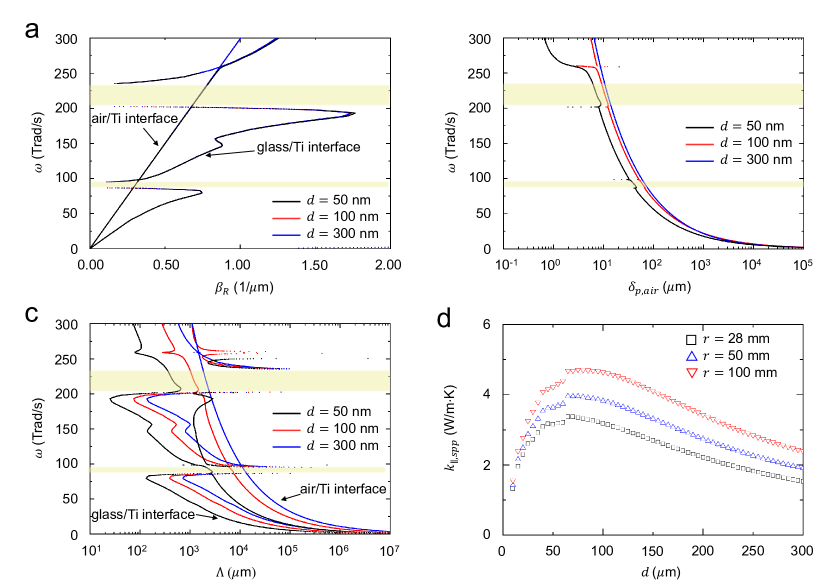
The real part of in-plane wavevector of Ti films deposited on glass substrates with nm, 100 nm, and 300 nm is plotted in Fig. 3a. The dispersion curves are drawn for a frequency range from 0 to 300 Trad/s because the calculated spectral thermal conductivity of the Ti film on the glass substrate (i.e., ) has considerable value at frequency lower than 300 Trad/s when maximum propagation length, is set to be 28 mm (see Fig. S8). In Fig. 3a, it is clearly seen that there exist two branches of SPP dispersion, which are originated from the SPPs at two interfaces of Ti film. For metal film with asymmetric surrounding dielectrics, symmetric mode which has longer propagation length is supported at the interface between metal and dielectric with lower refractive index (i.e., lower at a given frequency) [8]. In other words, the symmetric mode of SPPs is supported at the air/Ti interface and has longer propagation length than that supported at the glass/Ti interface (see Fig. 3c). Because much longer propagation can be obtained for SPPs from air/Ti interface, following discussion will be mainly focused on the SPPs at the air/Ti interface.
At the interface between a semi-infinite air and a semi-infinite Ti, a SPP dispersion follows the light line of air (i.e., photon-like behavior) in the sufficiently low frequency region before reaching an asymptote at high frequency ( with being the plasma frequency of Ti) [3]. Although all of the dispersion curves at the air/Ti interface look similar and coincide with the air light line regardless of the thickness of the Ti film in Fig. 3a, there exists a slight difference near the air light line for different thicknesses of Ti films (Fig. S9). As decreases, the dispersion deviates from the air light line due to the coupling of the SPPs supported at the air/Ti interface and those at the glass/Ti interface. Importantly, the deviation of from the light line leads to the confinement of SPPs at the interface. Fig. 3b depicts the skin depth of SPPs from the air/Ti interface (i.e., the penetration depth into air) with respect to film thickness, where . As the separation between and the light line becomes smaller, the field can penetrate deeper into surrounding air, resulting in a longer propagation length, as in Fig. 3c. Thus, SPPs with a long propagation length exist for thick Ti films where the SPPs at the air/Ti interface are located close to the light line. Although not shown here, with nm is essentially overlapped with that with nm, suggesting that 300-nm-thick Ti film is already too thick for coupling of SPPs at both interfaces.
For a freestanding SiO2 membrane, surface waves propagate longer when the membrane is thinner [9]. Such discrepancies result from the different optical properties of a lossy metal and a polar dielectric. For a SiO2 membrane, the Zenneck surface modes ( and , where and represent real and imaginary parts of the permittivity of the thin film) dominate thermal conductivity by surface waves, while metal thin films can support SPPs (i.e., ) in a broad frequency range. Thus, the energy loss of surface waves decreases as film thickness decreases for SiO2 membrane, leading to a longer propagation length. Also, for a metal film surrounded by same dielectrics, a symmetric SPP mode approaches the light line as the thickness of the metal film decreases and the coupling of SPPs at each metal/dielectric interface becomes significant [8, 15], resulting in longer propagation length of SPPs.
Contrarily, for a thin metal film on a dielectric substrate, SPPs can propagate longer along the interface when the film thickness is greater than the penetration depth of the metal film, so SPPs at the air/Ti interface can approach the air light line. In fact, when the analytic solution for the SPP dispersion at the single interface of semi-infinite metal/dielectric [8]is applied, the resulting dispersion is almost equal to that of a metal film with nm (Section 11 of Supplemental Material), which implies that the SPPs of each interface are nearly decoupled and shows the characteristics of a semi-infinite metal/dielectric interface.
At low frequencies below 100 Trad/s, the SPP propagation lengths can be longer than 1 cm, causing the radius-dependence of in Fig. 2b. Considering that the effective propagation length of SPP is given by , the radius of samples mostly limits low-frequency SPPs under 100 Trad/s if cm. Equation (3) also suggests that also determines the SPP thermal conductivity. This is the reason why the 302.7-nm-thick Ti film has lower than the 108.2-nm-thick Ti film even though it has longer . In other words, the contribution of thermal conduction via SPPs can be substantial in thin films, although the SPPs can propagate longer for thicker films, implying the existence of an optimum thickness for SPP-enhanced thermal conductivity.
Figure 3d shows the calculated with respect to Ti film thickness when mm (i.e., maximum sample size), 50 mm, and 100 mm. Because of the interplay between the factor of and in Eq. (3), the optimal thickness exists at a given radius . For the considered Ti film deposited on a glass substrate, the optimal thickness is approximately 70 nm. As decreases below 70 nm, the reduction of SPP propagation length (due to coupling of SPPs at both interfaces) results in decreased . On the other hand, as increases beyond 70 nm, the factor of will eventually lead to decreased . Because the radiation penetration depth of Ti is approximately 40 nm in the infrared spectral region ( Trad/s), the coupling of SPPs may occur up to nm (i.e., three times the radiation penetration depth).
In conclusion, the SSTR measurements for the supported Ti film on glass substrate clearly demonstrate the thickness- and size-dependence of the surface-polariton-enhanced in-plane thermal conductivity. For the 108.2-nm-thick Ti film, the corresponding is nearly 40% of its intrinsic value (i.e., ) when mm. Due to broadband SPPs supported at an air/lossy metal interface, it is found that there exists an optimal thickness for the maximum . This study provides a practical approach for exploiting surface polariton to enhance in-plane thermal conductivity by introducing a supported metal thin film configuration, where the enhancement of thermal conductivity is almost impossible for polar-dielectric counterparts.
Acknowledgements.
Supplemental Material
See Supplemental Material at [URL will be inserted by publisher] for (1) Validation of experimental setup, (2) Sensitivity analysis of SSTR, (3) Summary of thermal properties used in 2-D heat diffusion model, (4) Optical property of Ti film, (5) Electron contribution of in-plane thermal conductivity of Ti film () measured by 4-probe measurement, (6) Measurement of cross-plane thermal conductivity of Ti film by using 3 method, (7) Fitting procedure and uncertainty of obtained by SSTR method, (8) Measurement of Ti film thickness with stylus profiler, (9) Spectral thermal conductivity of SPP, (10) Dispersion curve near the light line of air, (11) Analytic solution of SPP, (12) Beam diameter of probe and pump laser, and (13) Thermal conductivity of glass substrate. All files related to a published paper are stored as a single deposit and assigned a Supplemental Material URL. This URL appears in the article’s reference list.
Funding Sources
This research is supported by the Basic Science Research Program (NRF-2020R1A4 A4078930) through the National Research Foundation of Korea (NRF) funded by Ministry of Science and ICT.
References
- Qiu and Tien [1993] T. Qiu and C. Tien, Journal of heat transfer 115 (1993).
- Zhang [2007] Z. M. Zhang, Nano/microscale heat transfer, Vol. 410 (Springer, 2007).
- Raether [1988] H. Raether, Surface plasmons on smooth and rough surfaces and on gratings , 91 (1988).
- Mulet et al. [2001] J.-P. Mulet, K. Joulain, R. Carminati, and J.-J. Greffet, Applied Physics Letters 78, 2931 (2001).
- Chen et al. [2005] D.-Z. A. Chen, A. Narayanaswamy, and G. Chen, Physical Review B 72, 155435 (2005).
- Ordonez-Miranda et al. [2013] J. Ordonez-Miranda, L. Tranchant, T. Tokunaga, B. Kim, B. Palpant, Y. Chalopin, T. Antoni, and S. Volz, Journal of Applied Physics 113, 084311 (2013).
- Gluchko et al. [2017] S. Gluchko, B. Palpant, S. Volz, R. Braive, and T. Antoni, Applied Physics Letters 110, 263108 (2017).
- Burke et al. [1986] J. Burke, G. Stegeman, and T. Tamir, Physical Review B 33, 5186 (1986).
- Tranchant et al. [2019] L. Tranchant, S. Hamamura, J. Ordonez-Miranda, T. Yabuki, A. Vega-Flick, F. Cervantes-Alvarez, J. J. Alvarado-Gil, S. Volz, and K. Miyazaki, Nano letters 19, 6924 (2019).
- Joulain et al. [2005] K. Joulain, J.-P. Mulet, F. Marquier, R. Carminati, and J.-J. Greffet, Surface Science Reports 57, 59 (2005).
- Chen and Chen [2010] D.-Z. A. Chen and G. Chen, Frontiers in heat and mass transfer 1 (2010).
- Baffou et al. [2010] G. Baffou, C. Girard, and R. Quidant, Physical review letters 104, 136805 (2010).
- Wu et al. [2020] Y. Wu, J. Ordonez-Miranda, S. Gluchko, R. Anufriev, D. D. S. Meneses, L. Del Campo, S. Volz, and M. Nomura, Science advances 6, eabb4461 (2020).
- Chen and Chen [2007] D.-Z. A. Chen and G. Chen, Applied Physics Letters 91, 121906 (2007).
- Yang et al. [1991] F. Yang, J. Sambles, and G. Bradberry, Physical Review B 44, 5855 (1991).
- Lim et al. [2019] M. Lim, J. Ordonez-Miranda, S. S. Lee, B. J. Lee, and S. Volz, Physical Review Applied 12, 034044 (2019).
- Basu and Francoeur [2011] S. Basu and M. Francoeur, Applied Physics Letters 98, 113106 (2011).
- Biehs et al. [2012] S.-A. Biehs, M. Tschikin, and P. Ben-Abdallah, Physical review letters 109, 104301 (2012).
- Messina and Ben-Abdallah [2013] R. Messina and P. Ben-Abdallah, Scientific reports 3, 1 (2013).
- Liu et al. [2014] X. Liu, R. Zhang, and Z. Zhang, International Journal of Heat and Mass Transfer 73, 389 (2014).
- Jin et al. [2016] S. Jin, M. Lim, S. S. Lee, and B. J. Lee, Optics express 24, A635 (2016).
- Lim et al. [2018a] M. Lim, J. Song, J. Kim, S. S. Lee, I. Lee, and B. J. Lee, Journal of Quantitative Spectroscopy and Radiative Transfer 210, 35 (2018a).
- Lim et al. [2018b] M. Lim, J. Song, S. S. Lee, and B. J. Lee, Nature communications 9, 1 (2018b).
- Berini [2009] P. Berini, Advances in optics and photonics 1, 484 (2009).
- Braun et al. [2019] J. L. Braun, D. H. Olson, J. T. Gaskins, and P. E. Hopkins, Review of Scientific Instruments 90, 024905 (2019).
- Braun and Hopkins [2017] J. L. Braun and P. E. Hopkins, Journal of Applied Physics 121, 175107 (2017).
- Abad et al. [2017] B. Abad, D.-A. Borca-Tasciuc, and M. Martin-Gonzalez, Renewable and Sustainable Energy Reviews 76, 1348 (2017).
- Ordal et al. [1988] M. A. Ordal, R. J. Bell, R. W. Alexander, L. A. Newquist, and M. R. Querry, Applied optics 27, 1203 (1988).
- Ashcroft and Mermin [1976] N. W. Ashcroft and N. D. Mermin, Solid state physics (Harcourt college, 1976).
- Day et al. [1995] M. Day, M. Delfino, J. Fair, and W. Tsai, Thin Solid Films 254, 285 (1995).
- Ordonez-Miranda et al. [2014] J. Ordonez-Miranda, L. Tranchant, Y. Chalopin, T. Antoni, and S. Volz, Journal of Applied Physics 115, 054311 (2014).
- Palik [1998] E. D. Palik, Handbook of optical constants of solids, Vol. 3 (Academic press, 1998).