First design of a superconducting qubit for the QUB-IT experiment
Abstract
Quantum sensing is a rapidly growing field of research which is already improving sensitivity in fundamental physics experiments. The ability to control quantum devices to measure physical quantities received a major boost from superconducting qubits and the improved capacity in engineering and fabricating this type of devices. The goal of the QUB-IT project is to realize an itinerant single-photon counter exploiting Quantum Non Demolition (QND) measurements and entangled qubits, in order to surpass current devices in terms of efficiency and low dark-count rates. Such a detector has direct applications in Axion dark-matter experiments (such as QUAX[1]), which require the photon to travel along a transmission line before being measured. In this contribution we present the design and simulation of the first superconducting device consisting of a transmon qubit coupled to a resonator using the Qiskit-Metal software developed by IBM. Exploiting the Energy Participation Ratio (EPR) simulation we were able to extract the circuit Hamiltonian parameters, such as resonant frequencies, anharmonicity and qubit-resonator couplings.
1 Design
The design and simulation phase is fundamental in order to address the best circuit parameters for the superconducting qubit device before moving to manufacturing stage. The aim of our first design is to build a superconducting qubit that can be controlled and read through a resonator coupled to a feedline. For this chip we considered a substrate consisting of of silicon oxide on top of of silicon.
The design of our circuit was developed exploiting Qiskit-Metal [2] toolkit and it is shown in Fig. 1. The circuit consists of an Xmon-type qubit capacitively coupled to a quarter wave readout resonator. Each electrode of the Xmon cross is wide and long. The gap between the cross and the ground plane is wide. The readout resonator is long, with trace width and gap, matching a characteristic impedance . The coupling element is a long claw, with gap to the ground plane. The resonator is capacitively coupled to the feedline by a long coupling leg. The lumped element circuit equivalent to our design is shown in Fig. 2.
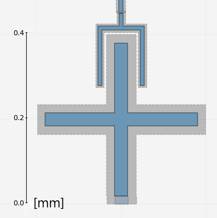
(a)
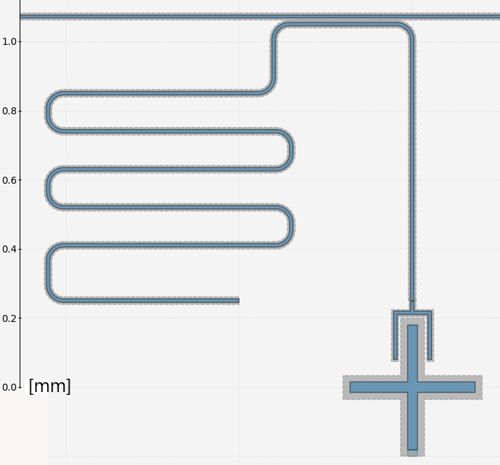
(b)

2 Simulations
The simulations are performed exploiting Ansys Q3D and Ansys HFSS111ANSYS Electronics Desktop 2021 R2. The former is used to extract the capacitance values for circuit elements. The simulated capacitances are , for the qubit shunt capacitance, and for the qubit-resonator and resonator-feedline coupling capacitances respectively. The lumped element equivalent inductance and capacitance for a quarter wave resonator can be calculated as:
| (1) | ||||
| (2) |
from [3].
The chosen value for the Josephson junction inductance is , matching a critical current of . With these circuit parameters we expect a Josephson energy and a capacitve energy , resulting in a ratio in the transmon regime. The qubit and readout resonator resonant frequencies are and respectively, leading to a detuning of .
The qubit-resonator coupling strength can be calculated as ([4]):
| (3) |
with , and elementary charge, leading to . We can then calculate the total dispersive shift as ([4]):
| (4) |
where .
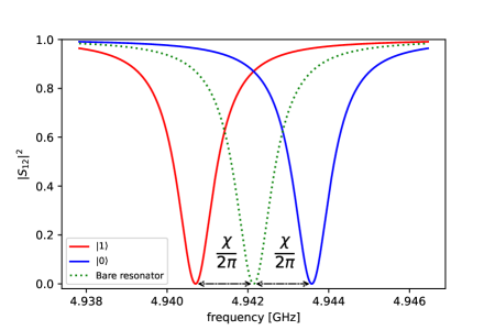
The total dispersive shift value is , being larger than the resonator resonance width allows the qubit state readout. Fig. 3 shows the expected transmission on the feedline as a function of frequency for the qubit in the ground or excited state.
An estimate of the qubit relaxation time can be calculated as follows ([5]):
| (5) |
where (calculated as in [6]) is the resonator quality factor.
Ansys HFSS is used to perform the eigenmode simulation in order to compute the resonant frequencies of the circuit and exploit the Energy Participation Ratio (EPR) simulation [7, 8]. From the EPR analysis we can extract the qubit and resonator frequencies, anharmonicities and the total dispersive shift. The simulated qubit and resonator frequencies are and respectively. These values match the expected frequencies within and respectively. The qubit anharmonicity extracted from the EPR simulation is and matches the expected within . The simulated value for the total dispersive shift is , within the expected value.
3 Conclusions
We were able to simulate one possible design for the first chip fabrication, comparing the results with the expected circuit features. The simulations agree with the calculated values within a few percents. It should be noted that longer and more accurate simulations could further reduce these gaps.
Before moving to the manufacturing stage, a similar design with inductive resonator-feedline coupling will be evaluated, as well as different qubit and Josephson junction parameters. Higher values for the anharmonicity and longer qubit relaxation time will be pursued by accurately tuning couplings and frequencies. Further parameter tuning is ongoing to optimize the qubit readout.
A simulation-data comparison will be performed as soon as the first chip is produced in order to validate the design procedure.
References
- [1] D. Alesini, et al., Search for invisible axion dark matter of mass meV with the QUAX– experiment, Phys. Rev. D 103 (10) (2021) 102004. arXiv:2012.09498, doi:10.1103/PhysRevD.103.102004.
- [2] Z. K. Minev, et al., Qiskit Metal: An Open-Source Framework for Quantum Device Design & Analysis (2021). doi:10.5281/zenodo.4618153.
- [3] D. Pozar, Microwave Engineering, 4th Edition, Wiley, 2011.
- [4] J. Koch, et al., Charge-insensitive qubit design derived from the cooper pair box, Physical Review A 76 (4). doi:10.1103/physreva.76.042319.
- [5] A. Blais, et al., Cavity quantum electrodynamics for superconducting electrical circuits: An architecture for quantum computation, Phys. Rev. A 69 (2004) 062320. doi:10.1103/PhysRevA.69.062320.
- [6] M. Göppl, et al., Coplanar waveguide resonators for circuit quantum electrodynamics, Journal of Applied Physics 104 (11) (2008) 113904. doi:10.1063/1.3010859.
- [7] Z. K. Minev, et al., Energy-participation quantization of josephson circuits (2020). doi:10.48550/arxiv.2010.00620.
- [8] Z. K. Minev, et al., pyEPR: The energy-participation-ratio (EPR) open-source framework for quantum device design (May 2021). doi:10.5281/zenodo.4744447.