Resonantly-driven nanopores can serve as nanopumps
Abstract
Inducing transport in electrolyte-filled nanopores with dc fields has led to influential applications ranging from nanosensors to DNA sequencing. Here we use the Poisson-Nernst-Planck and Navier-Stokes equations to show that unbiased ac fields can induce comparable directional flows in gated conical nanopores. This flow exclusively occurs at intermediate driving frequencies and hinges on the resonance of two competing timescales, representing space charge development at the ends and in the interior of the pore. We summarize the physics of resonant nanopumping in an analytical model that reproduces the results of numerical simulations. Our findings provide a generic route towards real-time controllable flow patterns, which might find applications in controlling the translocation of particles such as small molecules or nanocolloids.
Introduction –
In the past few years, nanochannels and nanopores have been the subject of rapidly intensifying research activities. They have found applications as nanosensors [1, 2], in DNA sequencing [3, 4], for liquid and gas-phase separation processes [5], for water desalination by reverse osmosis [6], or for power generation from salinity gradients [7].
For many applications of electrolyte-filled nanochannels and nanopores, it is desirable to control the transport processes inside the channels or pores. For such purposes, control schemes based on a gate voltage, often applied via a gate electrode, have been developed. By tuning the gate voltage, the electrostatic potential at the channel or pore walls can be modulated. In turn, the charge in the diffuse part of the electric double layer (EDL) can be controlled, which is especially interesting in the case of overlapping EDLs. In experiments it was demonstrated that corresponding schemes enable controlling the transport properties of nanopores. Examples include the control of water permeation [8] and DNA translocation [9, 10, 11], and more generally, the control of electromigration and diffusion fluxes through nanopores [12, 13, 14, 15, 16, 17] which can even be rectified [18, 19, 20, 21]. As for the latter, employing nanopores with conical or converging geometries has proven particularly useful [22, 23]. For example, when filled with an electrolyte solution, their electric resistance can become direction-dependent, giving such pores current-rectifying properties [24, 25, 26]. This results in asymmetric current-voltage I(V) curves, such that the magnitude of the resulting current depends on the sign of the applied dc voltage [27].
Notably, to date, most existing transport control and rectification schemes in nanopores employ a dc driving (or a slow ac-driving), based on a constant applied voltage, such that the transport properties are essentially controlled by the equilibrium or steady-state properties of the system. Compared to that, dynamic aspects have received little attention.
In the present work, we explore the transport properties of conical nanopores under the influence of ac driving, i.e. for gate-electrodes energized with frequencies high enough to keep the ion cloud in the pore persistently away from its equilibrium configuration. By combining simulations of the Poisson-Nernst-Planck (PNP) and Navier-Stokes (NS) equations and analytical modeling, we show that an ac driving induces a novel and subtle transport mechanism in which the pore serves as a nanopump creating a net fluid flow – even in the absence of a direction-dependent flow resistance. Remarkably, the pumping neither occurs for very slow or very fast driving, but the maximum flow rate is reached at a characteristic resonance frequency which can be determined by the intrinsic relaxation rate of the system in response to a step change in voltage. We call this mechanism resonant nanopumping. We explain the mechanism using an analytical model which predicts the multi-dimensional parametric dependency of the flow rate, in quantitative agreement with our detailed simulations.
Our results unveil a novel nanopumping principle which offers the ac driving frequency as a parameter to control the transport through a pore.
In addition, we note that the present work links the physics of nanopores to Brownian ratchets [28, 29, 30] and could induce a transfer of ideas between these research fields.
Setup –
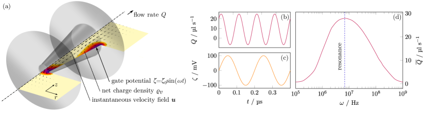
We consider a conical nanopore with length nm, a radius at the narrow end nm and an opening angle of , which connects two reservoirs filled with an aqueous, monovalent, binary electrolyte solution (Fig. 1). To avoid singularities, the corners at the two ends of the pore are blunted with a radius of 1 nm. Both reservoirs feature the same prescribed pressure and ion concentrations , and their boundaries far from the pore (cropped in Fig. 1a) are grounded. Ion concentrations such that the Debye length is smaller than are chosen. The pore wall is assumed to exhibit no native zeta potential and the gate potential at the wall can be varied. The pore and reservoir walls (grey in Fig. 1a) are considered non-slipping and impermeable for ions.
Flow field –
Let us now explore the flow through the pore when applying an ac gate potential of angular frequency . To do this, we numerically solve the fully coupled set of PNP and NS equations on this axisymmetric two-dimensional geometry using the finite-element method (see Supplemental Material (SM) for details). We monitor the flow rate (Fig. 1b and d), where is the axial velocity and is any cross-sectional plane within the pore.
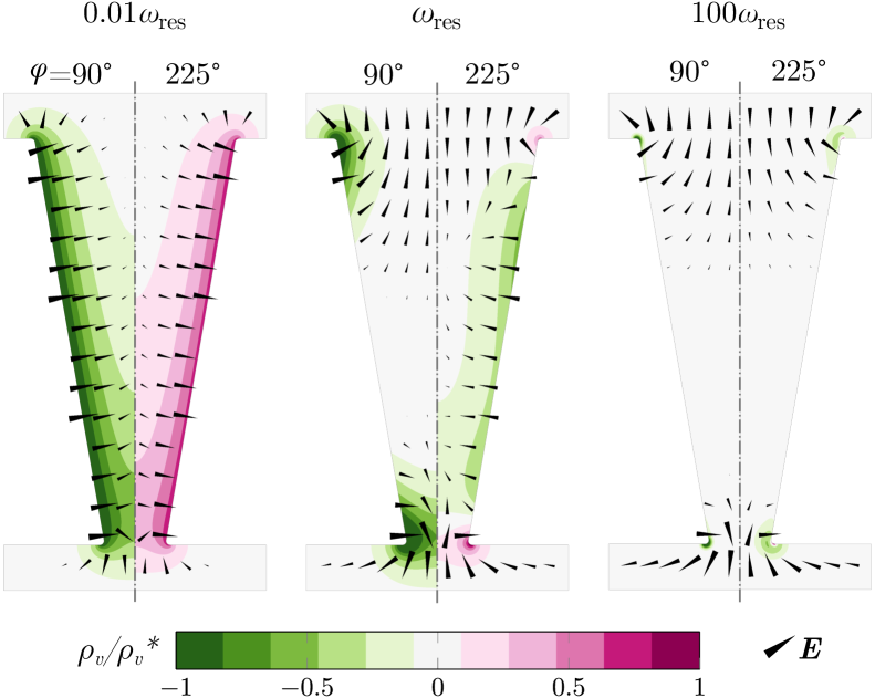
When tends towards zero, we observe that the time-averaged flow vanishes (Fig. 1d). This is plausible, as for slow driving anions and cations alternately enter and leave the pore via both openings and form fully developed EDLs along the entire pore wall over the full driving cycle (Fig. 2, left panel).
Consequently, the electric body force within the equilibrium EDLs is counteracted by the electrohydrostatic (osmotic) pressure gradient and the net force on the fluid vanishes at all times [31].
Similarly, when tends towards infinity, we observe a rapidly oscillating but very weak flow , and again tends towards zero (Fig. 1d).
Reason is that
for very fast driving, ions are alternately driven towards and away from the pore wall to screen the gate potential, but do not have enough time to migrate into the pore. Accordingly, we observe small () charged regions at the corners, whereas the liquid around the pore center remains uncharged (Fig. 2, right panel). In this case, charged regions are virtually absent and the flow is very weak.
Remarkably, however, for
intermediate , we observe
a significant flow. It oscillates with twice the driving frequency and shows a strong bias, such that the net flow points from the narrow to the wide end of the pore (Fig. 1c).
The emergence of such a flow might surprise, since there are no apparent driving gradients, especially pressure gradients, induced by the boundary conditions.
To understand how this flow comes about, note that after each sign change of the gate potential, new EDLs start to form at both pore ends and spread towards the pore center. This process gets interrupted by the subsequent sign change of the gate potential such that the EDLs follow the gate potential with a delay, causing charge density gradients along the pore that result in significant axial electric fields at the pore ends. The middle panel of Fig. 2 even shows the simultaneous presence of oppositely charged regions.
These axial electric fields exert a body force on the charged liquid at the corners, that oscillates with twice the driving frequency , since both the charge density and the electric field oscillate with . Because of the conical pore shape, these body forces push fluid into the pore with different strength at the two ends, leading to the observed bias which we will further discuss and quantify below.
Step response and characteristic timescales –
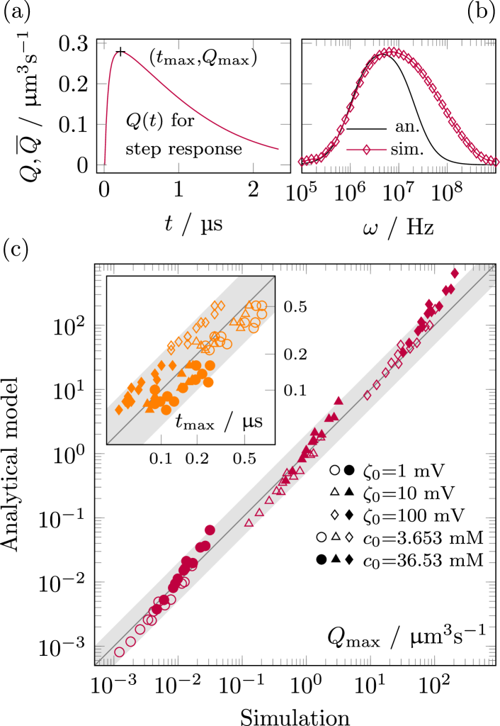
To understand the complex interplay of space charge and electric field, we explore the response of the system ( assumed to be in equilibrium at ) to a step-like gate potential where for and zero elsewise (method of step response [32]). Such a gate potential causes a fast increase of the flow rate towards a distinct maximum, which is followed by a comparatively slow relaxation towards the new equilibrium state (see Fig. 4a). That is, the system possesses two competing inherent timescales: a short one corresponding to the time needed for developing EDLs at the corners, and a long timescale corresponding to the time needed for the ions to migrate into the pore and develop an EDL throughout. Within the latter timescale, the axial electric field vanishes, ultimately leading to an electric field that points in wall-normal direction in all space-charge regions (Fig. 3, left splits).
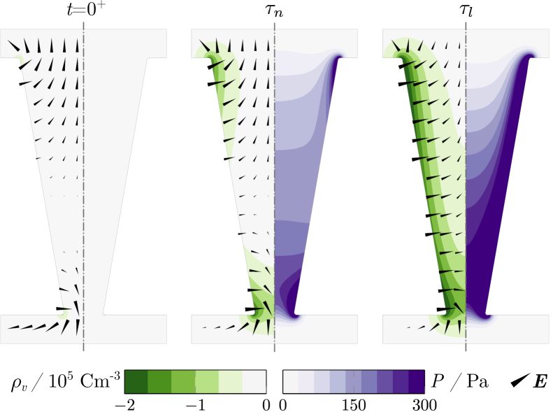
When one pore end is viewed independently, the only lengthscale that the electric field can depend on is the pore diameter. Thus, after switching on the gate potential at , there is a significant axial electric field which essentially persists over that lengthscale (Fig. 3, left and middle panels). Since the interaction of charges with this field drives the flow, we identify the short timescale as the time of diffusive transport of counterions into the pore over a length of one pore diameter to form EDLs at the corners of the pore (Fig. 3, middle panel). The transport of co-ions in the opposite direction proceeds in a similar manner. Notably, although can be in this work, we find that the charging timescale for a pore end largely follows the simple expression
| (1) |
obtained from the transmission line model (TLM) for (see [33] and SM). Here is the ion diffusivity and the subscripts and denote the narrow and wide ends, respectively.
The long timescale is associated with the filling of the complete pore with counterions, leading to fully evolved EDLs and to a cancellation of the axial electric field. It is the timescale of diffusive transport of ions from both pore ends over a distance of roughly , which is again derived from the TLM as (see SM)
| (2) |
where is the mean-radius of the conical pore.
Delay effects drive the nanopump –
We now further resolve the crucial role of delay effects for the operation of the nanopump. To this end, note first that for the step response the axial electric body force only acts in the time window when has already developed and has not yet vanished, i.e. roughly for .
Within this time window, the body force pushes liquid into the pore from both ends, irrespective of the sign of . The conical pore shape breaks the reflection symmetry with respect to , making the force contributions from both ends unequal. As a result of these localized forces, an axial pressure gradient develops (Fig. 3, right split) and liquid flows from the narrow to the wide end.
Accordingly, when driving the pore with an ac voltage with a frequency large enough to cause significant delay effects, but small enough to allow EDLs to partially propagate into the pore, we observe unequal oscillating axial body forces at both ends of the pore that drive liquid through it.
Analytical model –
To quantitatively predict the flow through the nanopore, we translate the localized axial body force contributions into effective pressures at both pore ends, matching the pressure field emerging in reaction to these forces (see Fig. 3, middle panel). We then solve Reynolds’ lubrication equation to predict the resulting flow.
The effective local pressure at either pore end can be estimated by area-averaging the axial electric body force, assuming it is fully present only in an annular region of width – corresponding to the EDL – with an axial extension comparable to the pore radius. For the step potential, this yields a time dependent pressure at a pore end of
| (3) |
where we use tildes to denote characteristic scales and assume exponential decay on each timescale, due to the capacitor-like charging of the EDL [34]. Clearly, this pressure is higher at the narrow end of the pore. We estimate the characteristic volume charge via the Debye-Hückel approximation as , with temperature and the Faraday and gas constants and , respectively. (See SM for details). Assuming, again, that the electric field at both pore ends first emerges on a lengthscale comparable to the pore diameter (Fig. 3) yields . The pressures in eqn. 3 are proportional to the product of the step responses of volume charge and axial electric field. Thus, we find the time-dependent pressures in response to an ac gate potential from the step responses [35] and again area-average their product (see SM):
| (4) |
| (5) |
The first term in braces is a frequency-dependent constant offset and the second term describes a harmonic oscillation with twice the driving frequency and a frequency-dependent phase shift. To translate the effective pressures at the pore ends into a flow rate, we analytically solve Reynolds’ lubrication equation for a pressure-driven flow in a conical pore, yielding (SM)
| (6) |
where is the dynamic viscosity of the liquid. The resonance frequency readily follows from this expression by (numerically) solving for . Overall, eqns. 4-6 (or 3 and 6) represent a full analytical model of the flow rate through the conical nanopore for a harmonic (or step-like) gate potential, which does not contain any free parameters. The model is expected to make valid predictions if and .
Comparison between model and numerical simulations –
Let us now systematically test the model by comparing it to our numerical simulations.
To do this, we compare the maximum flow rate and the time where this maximum occurs for the
step response simulations (Fig. 4a) in a 5-dimensional parameter space with mV, mol m-3, nm, nm, and .
The result shows a good agreement over the entire domain of the parameter space (Fig. 4c), even for , which is beyond the regime where our assumptions are justified.
Note that due to the linearity of the underlying charging processes, the comparison for the step response is largely representative also for the harmonic gate potential.
As exemplarily shown in Fig. 4b, the model correctly predicts the mean flow rate up to the resonance frequency.
Noticeable deviations at larger frequencies can be attributed to the fact that the model assumes driving axial fields at the pore ends only governed by the delay of screening charge at the pore center (timescale ).
However, at high frequencies, the pore center remains uncharged at all times and otherwise negligible variations due to the local dynamics of charge generation at the corners (timescale ) become dominant. This introduces nonlinearities that are not accounted for in the model.
Experimental feasibility –
Several studies have proven manufacturability of gated nanopores [12, 36] including conical shapes of similar dimensions as previously discussed [18, 37]. The proposed mode of resonant ac driving is thus practically realizable. Moreover, it is not limited to the pore dimensions considered above, since the fundamental physical mechanism applies more broadly.
Conclusions and outlook –
To conclude, we have demonstrated that electrolyte-filled conical nanopores with gate electrodes create a net flow when an ac voltage is applied to the gate. We have explained the emergence of a net flow as a resonance phenomenon that is based on two competing timescales. Achievable flow velocities range from millimeters to centimeters per second, which is comparable to electroosmotic flow in nanochannels and other nanopumping principles [26-32]. Resonant nanopumping could allow real-time flow regulation in individually addressable nanopores, where the voltage amplitude and driving frequency serve as parameters to control the magnitude and temporal structure of the flow field. Generally, gated transport through nanopores under ac driving could open up superior possibilities for selective mass transfer, like in the case of macromolecules or nanoparticles. As an example, the principle could prove beneficial for controlling DNA translocation in sequencing applications. Last but not least, the physical mechanisms related to flow induced by transient electric double layers uncovered in this work could find applications with a number of different electrode structures beyond conical shapes.
Acknowledgements.
We wish to acknowledge the help provided by Maximilian T. Schür in preparation of the figures.S. H. and B. L. proposed the work, A. D. R. and D. P. carried out the simulations, A. D. R. developed the theoretical framework and the analytical model, A. D. R., B. L. and S. H. contributed to the interpretation of the results, A. D. R., B. L. and S. H. prepared the manuscript, and S. H. and S. B. supervised the work.
References
- Zhang and Zhang [2021] D. Zhang and X. Zhang, Small (Weinheim an der Bergstrasse, Germany) 17, e2100495 (2021).
- Rahman et al. [2021] M. Rahman, M. J. N. Sampad, A. Hawkins, and H. Schmidt, Lab on a Chip 21, 3030 (2021).
- Wanunu [2012] M. Wanunu, Physics of Life Reviews 9, 125 (2012).
- Feng et al. [2015] Y. Feng, Y. Zhang, C. Ying, D. Wang, and C. Du, Genomics, Proteomics & Bioinformatics 13, 4 (2015).
- Wang et al. [2020] S. Wang, L. Yang, G. He, B. Shi, Y. Li, H. Wu, R. Zhang, S. Nunes, and Z. Jiang, Chemical Society Reviews 49, 1071 (2020).
- Liu et al. [2021] Y. Liu, Z. Zhang, and S. Wang, ACS ES&T Water 1, 34 (2021).
- Macha et al. [2019] M. Macha, S. Marion, V. V. R. Nandigana, and A. Radenovic, Nature Reviews Materials 4, 588 (2019).
- Zhou et al. [2018] K.-G. Zhou, K. S. Vasu, C. T. Cherian, M. Neek-Amal, J. C. Zhang, H. Ghorbanfekr-Kalashami, K. Huang, O. P. Marshall, V. G. Kravets, J. Abraham, Y. Su, A. N. Grigorenko, A. Pratt, A. K. Geim, F. M. Peeters, K. S. Novoselov, and R. R. Nair, Nature 559, 236 (2018).
- Yen et al. [2012] P.-c. Yen, C.-h. Wang, G.-J. Hwang, and Y. C. Chou, The Review of Scientific Instruments 83, 034301 (2012).
- Liu and Yobas [2016] Y. Liu and L. Yobas, ACS Nano 10, 3985 (2016).
- Xue et al. [2018] L. Xue, P. Cadinu, B. Paulose Nadappuram, M. Kang, Y. Ma, Y. Korchev, A. P. Ivanov, and J. B. Edel, ACS Applied Materials & Interfaces 10, 38621 (2018).
- Karnik et al. [2005] R. Karnik, R. Fan, M. Yue, D. Li, P. Yang, and A. Majumdar, Nano Letters 5, 943 (2005).
- Fuest et al. [2015] M. Fuest, C. Boone, K. K. Rangharajan, A. T. Conlisk, and S. Prakash, Nano Letters 15, 2365 (2015).
- Fuest et al. [2017] M. Fuest, K. K. Rangharajan, C. Boone, A. T. Conlisk, and S. Prakash, Analytical Chemistry 89, 1593 (2017).
- Cheng et al. [2018] C. Cheng, G. Jiang, G. P. Simon, J. Z. Liu, and D. Li, Nature Nanotechnology 13, 685 (2018).
- Ren et al. [2018] C. E. Ren, M. Alhabeb, B. W. Byles, M.-Q. Zhao, B. Anasori, E. Pomerantseva, K. A. Mahmoud, and Y. Gogotsi, ACS Applied Nano Materials 1, 3644 (2018).
- Xue et al. [2021] Y. Xue, Y. Xia, S. Yang, Y. Alsaid, K. Y. Fong, Y. Wang, and X. Zhang, Science (New York, N.Y.) 372, 501 (2021).
- Kalman et al. [2009] E. B. Kalman, O. Sudre, I. Vlassiouk, and Z. S. Siwy, Analytical and Bioanalytical Chemistry 394, 413 (2009).
- Guan et al. [2011] W. Guan, R. Fan, and M. A. Reed, Nature Communications 2, 506 (2011).
- Laucirica et al. [2019] G. Laucirica, W. A. Marmisollé, M. E. Toimil-Molares, C. Trautmann, and O. Azzaroni, ACS Applied Materials & Interfaces 11, 30001 (2019).
- Li and Li [2021] J. Li and D. Li, Journal of Colloid and Interface Science 596, 54 (2021).
- Apel et al. [2001] P. Apel, Y. Korchev, Z. Siwy, R. Spohr, and M. Yoshida, Nuclear Instruments and Methods in Physics Research Section B: Beam Interactions with Materials and Atoms 184, 337 (2001).
- Poggioli et al. [2019] A. R. Poggioli, A. Siria, and L. Bocquet, The Journal of Physical Chemistry. B 123, 1171 (2019).
- Wei et al. [1997] C. Wei, A. J. Bard, and S. W. Feldberg, Analytical Chemistry 69, 4627 (1997).
- Siwy et al. [2002] Z. Siwy, Y. Gu, H. A. Spohr, D. Baur, A. Wolf-Reber, R. Spohr, P. Apel, and Y. E. Korchev, Europhysics Letters (EPL) 60, 349 (2002).
- Siwy and Fuliński [2002] Z. Siwy and A. Fuliński, Physical Review Letters 89, 198103 (2002).
- Jin et al. [2010] P. Jin, H. Mukaibo, L. P. Horne, G. W. Bishop, and C. R. Martin, Journal of the American Chemical Society 132, 2118 (2010).
- Reimann [2002] P. Reimann, Physics Reports 361, 57 (2002).
- Hänggi and Marchesoni [2009] P. Hänggi and F. Marchesoni, Reviews of Modern Physics 81, 387 (2009).
- Denisov et al. [2014] S. Denisov, S. Flach, and P. Hänggi, Physics Reports 538, 77 (2014).
- Levich [1962] V. G. Levich, Physiochemical hydrodynamics, Prentice-hall international series in the physical and chemical engineering science (Prentice-Hall, Englewood Cliffs, N.J., 1962).
- Leigh [2012] J. R. Leigh, Control theory, 3rd ed., IEE control engineering series, Vol. 72 (Inst. of Electrical Engineers, London, 2012).
- Mirzadeh et al. [2014] M. Mirzadeh, F. Gibou, and T. M. Squires, Physical Review Letters 113, 097701 (2014).
- Janssen [2021] M. Janssen, Physical review letters 126, 136002 (2021).
- Berns et al. [2021] K. Berns, A. Köpper, and B. Schürmann, Technical Foundations of Embedded Systems, Vol. 732 (Springer International Publishing, Cham, 2021).
- Joshi et al. [2010] P. Joshi, A. Smolyanitsky, L. Petrossian, M. Goryll, M. Saraniti, and T. J. Thornton, Journal of Applied Physics 107, 054701 (2010).
- Nam et al. [2009] S.-W. Nam, M. J. Rooks, K.-B. Kim, and S. M. Rossnagel, Nano Letters 9, 2044 (2009).
See pages 1 of Sup_Mat.pdf See pages 2 of Sup_Mat.pdf See pages 3 of Sup_Mat.pdf See pages 4 of Sup_Mat.pdf See pages 5 of Sup_Mat.pdf See pages 6 of Sup_Mat.pdf