Controlling polarization of spintronic THz emitter by remanent magnetization texture
Abstract
Terahertz (THz) sciences and technologies have contributed to a rapid development of a wide range of applications and expanded the frontiers in fundamental science. Spintronic terahertz emitters offer conceptual advantages since the spin orientation in the magnetic layer can be easily controlled either by the externally applied magnetic field or by the internal magnetic field distribution determined by the specific shape of the magnetic elements. Here, we report a switchable terahertz source based on micropatterned magnetic heterostructures driven by femtosecond laser pulses. We show that the precise tunability of the polarization state is facilitated by the underlying magnetization texture of the magnetic layer that is dictated by the shape of the microstructure. These results also reveal the underlying physical mechanisms of a nonuniform magnetization state on the generation of ultrafast spin currents in the magnetic heterostructures. Our findings indicate that the emission of the linearly polarized THz waves can be switched on and off by saturating the sample using a biasing magnetic field, opening fascinating perspectives for integrated on-chip THz devices with wide-ranging potential applications.
Terahertz (THz) devices, which operate in the frequency range from 0.1 THz to 30 THz in the electromagnetic spectrum, have significantly impacted various fields such as spectroscopy, sensing, and imaging Peiponen et al. (2013). Many applications in modern life, such as medical diagnosis, security, non-destructive industrial inspection, and non-ionizing imaging, are based on THz radiation. Functional THz components could further advance these technologies. While there has been significant progress in the past decades, THz components that allow for an effective control of THz functionalities such as the precise polarization state are still scarce Khusyainov et al. (2021); Yang et al. (2016). The manipulation of the polarization of THz radiation is a crucial aspect in creating versatile integrated THz devices and circuits. However, the development of such components is hampered by the lack of the required functionalities traditional THz sources can provide: typically, high-intensity THz sources capable of manipulating the polarization are narrow-band, limiting possible applications Kong et al. (2019). These traditional emitters exploit the electron’s charge degree of freedom and rely either on semiconductor based photoconductive antennas or nonlinear crystals Wu et al. (2021).
However, the additional spin-degree of freedom of electrons enables functionalities that could further advance THz technologies, e.g., biomedicine, materials science, physics, and chemistry. These spintronic THz emitters are based on magnetic heterostructures that comprise ferromagnetic metal/heavy metal layers Wu et al. (2021); Seifert et al. (2021). Upon excitation with a femtosecond laser pulse they emit THz radiation that is both highly efficient and broadband Kampfrath et al. (2013); Seifert et al. (2016); Yang et al. (2016); Huisman et al. (2016); Seifert et al. (2017); Jungfleisch et al. (2018); Walowski and Münzenberg (2016); Zhou et al. (2018); Torosyan et al. (2018); Nenno et al. (2019); Wu et al. (2020); Sharma et al. (2021), which enables the realization of functional THz components with emergent properties based on the spin orientation in the ferromagnetic layer. The THz generation process in spintronic emitters Wu et al. (2021) can be understood as a laser-driven ultrafast demagnetization of the ferromagnetic layer Beaurepaire et al. (1996), leading to the formation of a spin-polarized current that diffuses in the adjacent heavy metal layer Battiato et al. (2012); Rudolf et al. (2012); Nenno et al. (2018), where it is converted into a charge current due to the inverse spin Hall effect Dyakonov and Perel (1971); Hirsch (1999); Hoffmann (2013):
| (1) |
where is the spin-polarization vector, is the spin Hall angle of the heavy metal layer, and , are the charge and spin currents, respectively. See supplemental material (SM) for a schematic illustration of the inverse spin Hall effect. The time-varying charge current burst then emits THz electromagnetic waves, described by Maxwell’s equations. An additional advantage of spintronic THz sources is that micro- and nanofabrication of magnetic thin films are readily available, which opens up the possibility to tailor THz properties by design.
Previously, microstructured stripes made of magnetic heterostructures were discussed as a means to modify the THz emission characteristics Wu et al. (2020) and it was shown that thin film magnetic heterostructures exposed to an inhomogeneous magnetic field distribution can be utilized to create elliptical THz waves Kong et al. (2019). Another approach to control the THz radiation in spintronic emitters is to utilize the remanent magnetization texture such as magnetic vortices and antivortices or magnetic skyrmions Shinjo et al. (2000); Cowburn et al. (1999).
Here, we report a broadband magnetic-field controllable THz source based on the magnetization texture facilitated by micropatterned magnetic heterostructures with broken mirror symmetry. For this purpose, we use lithographically-defined arrays of a W/Fe/Pt trilayer grown on sapphire. We show that the precise tunability of the polarization state is facilitated by the underlying magnetization texture of the Fe layer that is determined by the exact shape of the elements and the direction of the applied field with respect to the microstructure. This interpretation is further supported by micromagnetic simulations. Our results further reveal how a nonuniform magnetization state affects the generation process of ultrafast spin currents in the microstructure and hence the properties of the emitted THz waves. Our findings indicate that a magnetic switch of linearly polarized THz source can be realized in microstructured geometries opening fascinating perspectives for integrated on-chip THz devices.
In the following, we describe the experimental methods including time-domain THz spectroscopy, sample fabrication, and micromagnetic modeling.
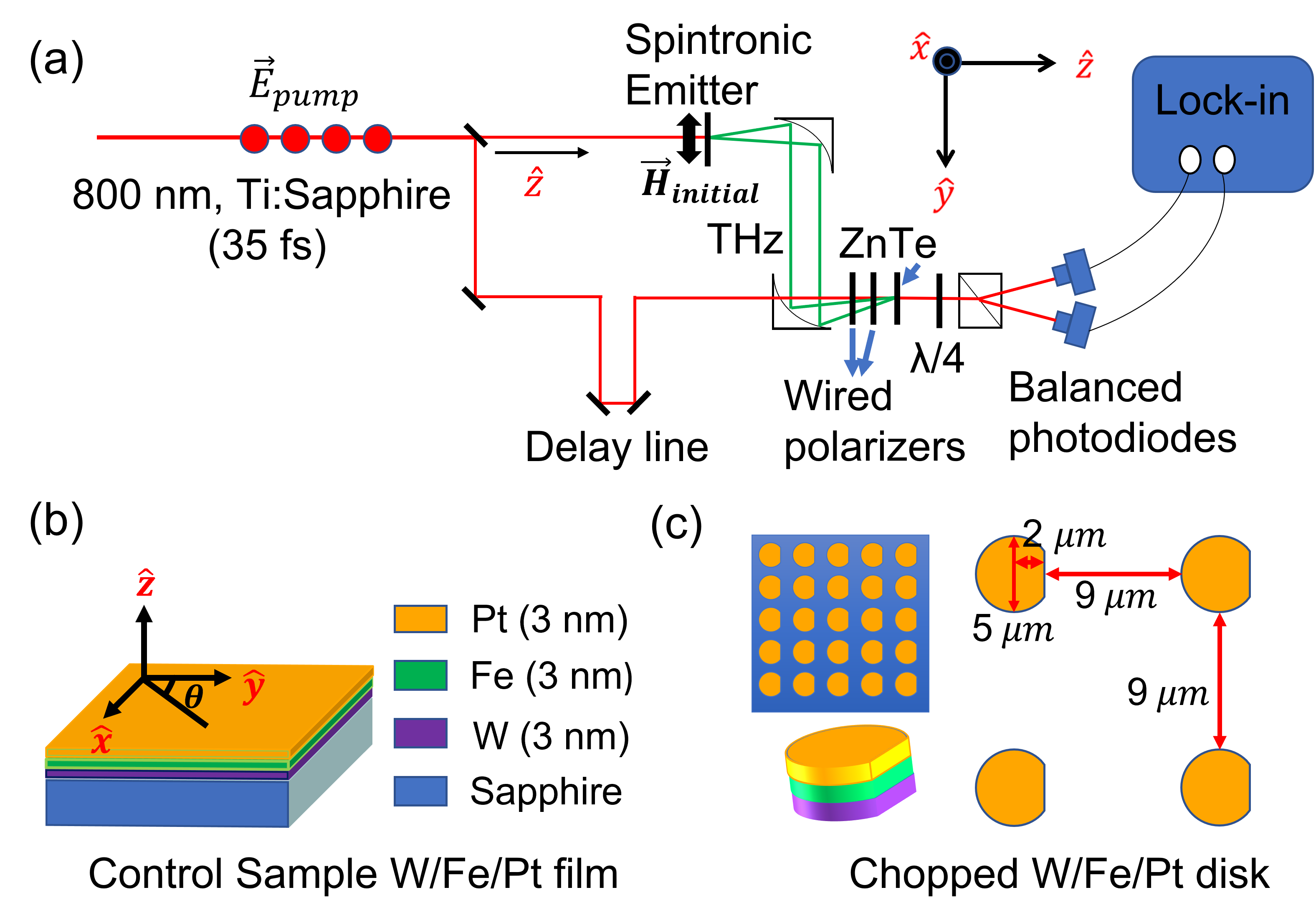
The experimental THz emission measurements are conducted using a standard time-domain THz spectroscopy (TDTS) system using electro-optical sampling with a 300 m-thick (110) ZnTe crystal, see Fig. 1(a). The laser system is a 800 nm Ti:Sapphire regenerative amplifier with a pulse width of 35 fs at a 2 kHz repetition rate and incident laser fluence below mJ/cm2. The THz traces are measured with a time resolution of 50 fs while the pumping laser beam is aligned perpendicular to the sample plane and faces the substrate material, see Fig. 1. An in-plane magnetic field (in -direction) is used to magnetize the sample to initially align the Fe magnetization (perpendicular or parallel to the direction of symmetry as discussed below).
To increase the intensity of the emitted THz radiation we sandwich the ferromagnetic layer (Fe) between two heavy metals with opposite spin Hall angles (W and Pt), see Fig. 1(b). Since the thickness of the used materials is small (nanometers), the THz radiation originating from the two heavy metal layers will have negligible phase difference. The samples were fabricated in the following fashion: we use optical lithography by a laser writer (Heidelberg MLA 100, minimum feature size: 1 m) to pattern an array of chopped disks (diameter: 5 m, asymmetric cut of the disk from its center: 2 m) with a separation of 9 m between inner edges on top of sapphire substrate. The sapphire substrate is with 0.5 mm thickness in the C-plane (0001). The cut of the disks is patterned parallel to one side of the substrate to easily align the external magnetic field with respect to the microstructured disk array. The detailed configuration is shown in Fig. 1(c). The metal layers W (thickness: 3 nm), Fe (thickness: 3 nm), and Pt (thickness: 3 nm) are grown using dc magnetron sputtering in an Ar atmosphere at 3 mTorr and 20 sccm gas flow (base pressure Torr) on double-side-polished sapphire substrates, followed by a lift-off process. Microscope and atomic force microscopy images of the measured samples are shown in the SM. A control W/Fe/Pt trilayer film was grown at the same time in the same deposition step.
We perform micromagnetic simulations using the graphic processing unit (GPU) accelerated software mumax3 Vansteenkiste et al. (2014) to determine the magnetization state of the microstructured disks. We simulated a primitive cell of lattice sites with periodic boundary conditions in the plane, and considering 3 repeated cells along each direction for the initial calculation of the dipolar field. Each disk with 5 m diameter and 3 nm thickness is cut 500 nm from one side to replicate the experimental conditions. The lattice is discretized in square-based elemental cells of nm3 and the whole structure consists of cells. 111The cell size is chosen larger than the exchange length of iron (2.4 nm) to reduce the computation time because our structure is fairly large. The magnetic parameters used for Fe are as follows: saturation magnetization kA/m and exchange stiffness J/m. For each applied magnetic field direction (parallel or perpendicular to the cut, respectively) we started with disks with random magnetization in each cell that were exposed to an external magnetic field with a magnitude of 8 mT, and then removed the field to obtain the final magnetization equilibrium state of the lattice. However, a field of 50 mT was used to initialize the samples in the experiments and all measurements were done in the remanent state.
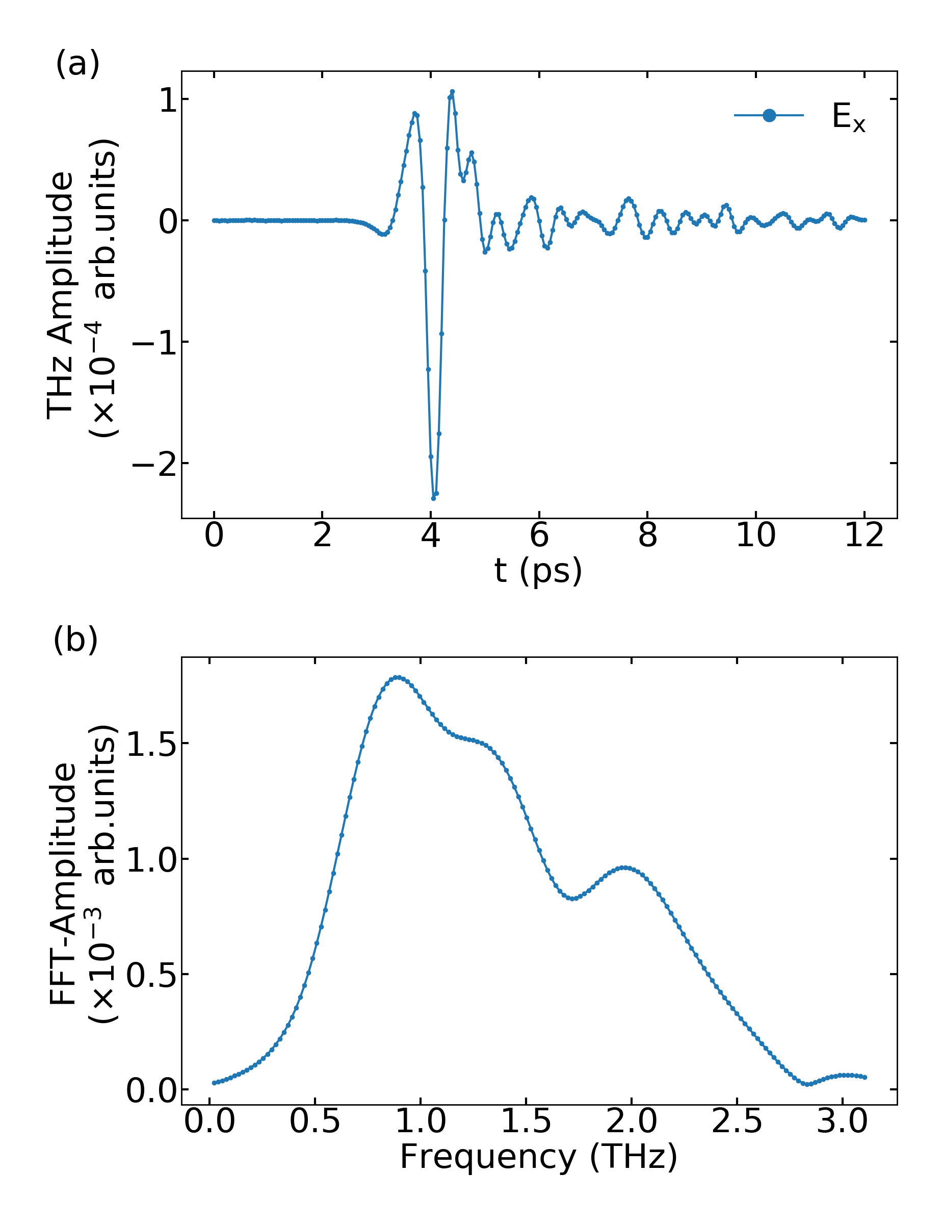
Figure 2(a) shows the time-domain trace of the THz signal (in -direction) generated by the W/Fe/Pt trilayer control film. In-plane angular dependent measurements agree with a spin-to-charge current conversion process by means of the inverse spin Hall effect, see SM. Moreover, we observe that the THz emission is independent from the helicity of the pump light, shown in Fig. S3 in the SM implying that inverse spin orbit torque Nemec et al. (2012), inverse Faraday effect Kimel et al. (2005), or inverse Rashba Edelstein effect Huisman et al. (2016); Jungfleisch et al. (2018) can be ruled out as possible sources of the observed THz emission 222Please note that when the sample is firstly magnetized and the field is then removed before the TDTS measurement, we also observe a contribution of the THz signal in -direction which likely stems from a not perfectly magnetized sample in -direction and/or an applied magnetizing field that is not large enough to saturate the Fe layer. The corresponding Fourier spectrum of this reference signal [shown in Fig. 2(b)] demonstrates that a broadband THz beam is generated.
In the following, we discuss the main observation of our work – the manipulation of the ultrafast spin current generation driven by femtosecond laser pulses facilitated by the underlying magnetization texture in the micropatterned magnetic heterostructure. As will be shown below, this control is robust and is enabled solely by the effective magnetic field distribution of the microstructure. Once the magnetic texture is initialized by an external biasing field, no additional external magnetic field is required; this is particularly useful for applications since the THz device itself does not require to be powered.
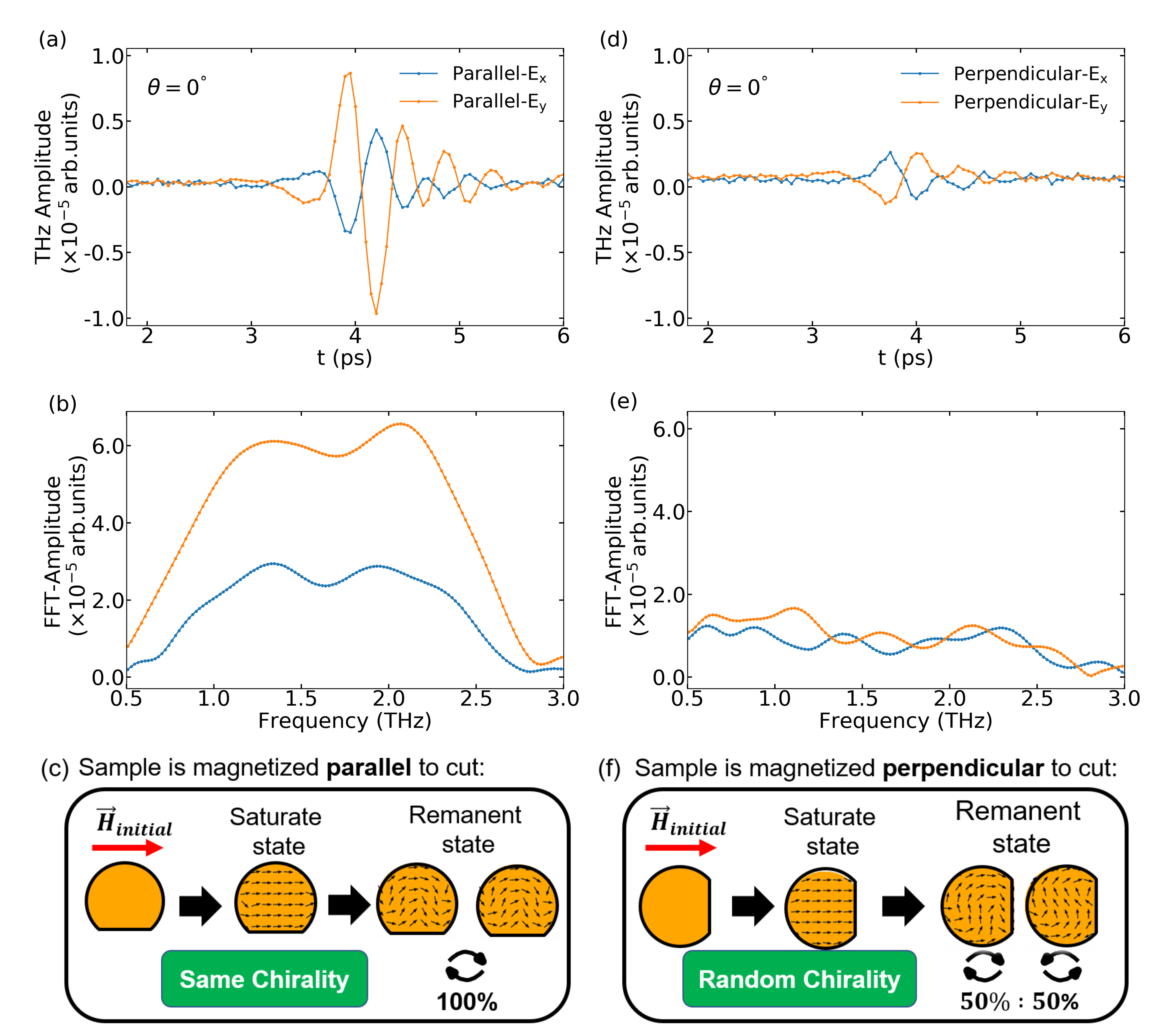
Our results show that it is possible to switch on or off linearly polarized THz waves by initializing the sample in either of two orthogonal directions, in the following called “parallel” and “perpendicular” to the cut. The peak amplitude of the THz signal of the chopped disks samples is about 1/20 of that of Fe/Pt bilayer film of the same thickness. This ratio is of the same order as the ratio of the two-dimensional hybrid metal halides with respect to the control sample (1/15) Cong et al. (2021). Two-dimensional hybrid metal halides are chiral magnetic materials for the generation of THz waves with asymmetric magnetic field dependence. For the initialization process a constant magnetic field is applied in the two directions, subsequently removed, and the measurements are performed without a magnetic field being applied. Since we expect a curled magnetization texture with magnetic moments lying in any direction in the -plane, we record the THz electric field amplitude in -direction, and in -direction, . Figure 3 shows the THz signals in the time domain and the corresponding fast-Fourier transform (FFT) spectra in the frequency domain in - and -direction when the sample is magnetized parallel and perpendicular to the cut, respectively. As is apparent from the figure, a negligibly small THz signal is observed when the sample is initially magnetized perpendicular to the cut. On the other hand, a clear signal is observed in both - and -direction when the sample is magnetized parallel to the cut. The ability to switch between the two states is reproducible and robust evidencing that this effect must originate from the magnetization configuration in the microstructured disks with broken mirror symmetry.
To further support our interpretation and to provide guidance on the exact underlying magnetization texture of the disks, we use micromagnetic modeling based on mumax3 (SM) Vansteenkiste et al. (2014). A schematic illustration explaining our observations is shown in the lower panel of Fig. 3; actual simulation results can be found in the SM. When the sample is firstly magnetized parallel to the cut, due to the broken mirror symmetry, only one of two possible magnetization configurations (either clockwise or counterclockwise depending on whether the initial field is applied in positive or negative -direction) predominantly exists in the remanent state, see schematic in Fig. 3(c). In other words, all magnetic microelements in the array feature the same chirality with magnetic moments identically distributed in the -plane (please note that the laser spot size is sufficiently large to excite a multitude of disks). This in turn leads to a THz emission with fixed linear polarization, and we can observe both and components, see Fig. 3(a). However, the situation drastically changes when the sample is magnetized perpendicular to the cut – the direction of mirror symmetry of the disks: now two configurations emerge in the remanent state with equal probabilities, resulting in a random distribution of chirality in each of the disks in the array, see schematic shown in Fig. 3(f). If both chiralities coexist in the sample, an overall cancellation of THz emission due to the near-zero net magnetization occurs. This is the reason why we observe a negligibly small signal when the sample is initialized perpendicular to the cut, see Figs. 3(d,e). Please note that we cannot rule out patterning imperfections in the actual samples, which may lead to a deviation from the theoretically expected 100% or 50% of the circularity probability distribution in the disks when initialized parallel or perpendicular to the cut, respectively.
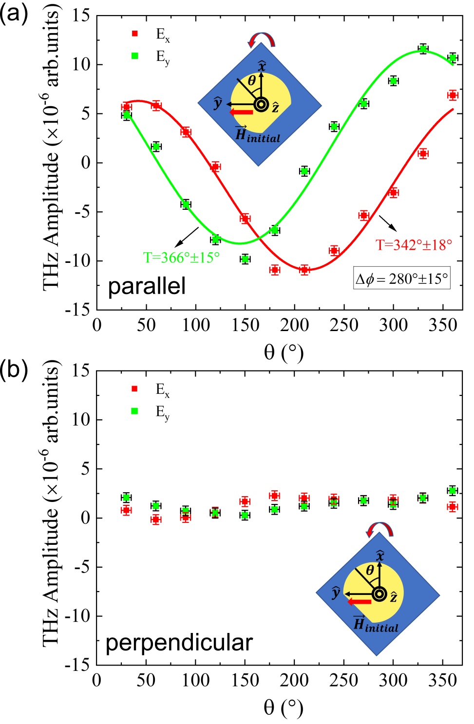
To further confirm our interpretation, we measure the dependence of the THz emission on the in-plane sample rotation angle [see Fig. 1(b)] around the -axis for initial magnetizing directions parallel and perpendicular to the cut, see Figs. 4(a,b). Figures 4(a,b) show the amplitude of the two orthogonal components of THz radiation and taken at identical delay times when the signal peaks in the time domain. As we would expect, the -component is maximum when the -component is minimum, and vice versa. The experimental data in Fig. 4(a) (symbols) are fitted with sinusoidal functions (solid lines) that confirm the periodic behavior: fits to the two components give a periodicity that is close to 360∘– a characteristic of ferromagnetic spintronic emitters relying on the inverse spin Hall effect Wu et al. (2021). As outlined in the detailed analysis presented in the SM, there may be an elliptical contribution to the THz signal. However, this effect is small. In contrast to the angular dependence when the disks are magnetized along the cut, negligible THz signal and angular variation are detected when the disks are initialized perpendicular to the cut, Fig. 4(b).
Finally, we note that an additional tuning variable could be a spatial variation of the thickness of the layers or their conductivities that would enable the control of the exact phase difference as well as the relative strength of the two orthogonal components. This approach may lead to a reliable generation of elliptically polarized THz waves with tunable ellipticity and polarization direction from spintronic emitters Kong et al. (2019).
We demonstrated an effective way to control and switch the linearly polarized THz radiation from femtosecond laser pulse driven spintronic microstructure emitters. We showed that the magnetic texture in the ferromagnetic layer controlled with the shape of the microstructure dictates the emitted THz waves. Our findings indicate that the emission of a polarized THz radiation can be controlled without an external magnetic field applied during the THz generation process with carefully designed microstructures. This goes beyond a recent proposal to harness permanently applied inhomogeneous magnetic fields Kong et al. (2019), opening fascinating perspectives for integrated on-chip THz devices with wide-ranging potential applications. Our results also reveal the underlying physical mechanisms of a nonuniform magnetization state on the generation process of ultrafast spin currents and the subsequent conversion in THz charge transients by the inverse spin Hall effect in the magnetic heterostructures. The proposed approach could potentially be used in spintronic emitters for the generation of elliptically polarized THz waves with tunable polarization, chirality, and ellipticity.
See the supplementary material for details on the inverse spin Hall effect, results of micromagnetic simulations, helicity-dependent THz emission, angular dependence of the control sample, microscope and atomic force microscopy images of the samples under investigation, and angular dependence of the total THz electric field.
Acknowledgements.
This work was supported by the National Science Foundation under Grant No. 1833000 and the University of Delaware Research Foundation (UDRF). Additional support received from the National Science Foundation through the University of Delaware Materials Research Science and Engineering Center, DMR-2011824. Work performed at the Center for Nanoscale Materials, a U.S. Department of Energy Office of Science User Facility, was supported by the U.S. DOE, Office of Basic Energy Sciences, under Contract No. DE-AC02-06CH11357. H. W. acknowledges support from the Department of Energy, Office of Science, Office of Basic Energy Sciences, Materials Sciences and Engineering Division..The authors have no conflicts to disclose.
References
- Peiponen et al. (2013) K.-E. Peiponen, A. Zeitler, and M. Kuwata-Gonokami, eds., Terahertz Spectroscopy and Imaging (Springer Berlin Heidelberg, 2013).
- Khusyainov et al. (2021) D. Khusyainov, S. Ovcharenko, M. Gaponov, A. Buryakov, A. Klimov, N. Tiercelin, P. Pernod, V. Nozdrin, E. Mishina, A. Sigov, and V. Preobrazhensky, Scientific Reports 11, 697 (2021).
- Yang et al. (2016) D. Yang, J. Liang, C. Zhou, L. Sun, R. Zheng, S. Luo, Y. Wu, and J. Qi, Advanced Optical Materials 4, 1944 (2016).
- Kong et al. (2019) D. Kong, X. Wu, B. Wang, T. Nie, M. Xiao, C. Pandey, Y. Gao, L. Wen, W. Zhao, C. Ruan, J. Miao, Y. Li, and L. Wang, Advanced Optical Materials 7, 1900487 (2019).
- Wu et al. (2021) W. Wu, C. Yaw Ameyaw, M. F. Doty, and M. B. Jungfleisch, Journal of Applied Physics 130, 091101 (2021), https://doi.org/10.1063/5.0057536 .
- Seifert et al. (2021) T. S. Seifert, L. Chen, Z. Wei, T. Kampfrath, and J. Qi, “Spintronic sources of ultrashort terahertz pulses,” (2021).
- Kampfrath et al. (2013) T. Kampfrath, M. Battiato, P. Maldonado, G. Eilers, J. Nötzold, S. Mährlein, V. Zbarsky, F. Freimuth, Y. Mokrousov, S. Blügel, M. Wolf, I. Radu, P. M. Oppeneer, and M. Münzenberg, Nature Nanotechnology 8, 256 (2013).
- Seifert et al. (2016) T. Seifert, S. Jaiswal, U. Martens, J. Hannegan, L. Braun, P. Maldonado, F. Freimuth, A. Kronenberg, J. Henrizi, I. Radu, E. Beaurepaire, Y. Mokrousov, P. M. Oppeneer, M. Jourdan, G. Jakob, D. Turchinovich, L. M. Hayden, M. Wolf, M. Münzenberg, M. Kläui, and T. Kampfrath, Nature Photonics 10, 483 (2016).
- Huisman et al. (2016) T. J. Huisman, R. V. Mikhaylovskiy, J. D. Costa, F. Freimuth, E. Paz, J. Ventura, P. P. Freitas, S. Blügel, Y. Mokrousov, T. Rasing, and A. V. Kimel, Nature Nanotechnology 11, 455 (2016).
- Seifert et al. (2017) T. Seifert, S. Jaiswal, M. Sajadi, G. Jakob, S. Winnerl, M. Wolf, M. Kläui, and T. Kampfrath, Applied Physics Letters 110, 252402 (2017).
- Jungfleisch et al. (2018) M. B. Jungfleisch, Q. Zhang, W. Zhang, J. E. Pearson, R. D. Schaller, H. Wen, and A. Hoffmann, Physical Review Letters 120, 207207 (2018).
- Walowski and Münzenberg (2016) J. Walowski and M. Münzenberg, Journal of Applied Physics 120, 140901 (2016).
- Zhou et al. (2018) C. Zhou, Y. P. Liu, Z. Wang, S. J. Ma, M. W. Jia, R. Q. Wu, L. Zhou, W. Zhang, M. K. Liu, Y. Z. Wu, and J. Qi, Physical Review Letters 121, 086801 (2018).
- Torosyan et al. (2018) G. Torosyan, S. Keller, L. Scheuer, R. Beigang, and E. T. Papaioannou, Scientific Reports 8, 1311 (2018).
- Nenno et al. (2019) D. M. Nenno, L. Scheuer, D. Sokoluk, S. Keller, G. Torosyan, A. Brodyanski, J. Lösch, M. Battiato, M. Rahm, R. H. Binder, H. C. Schneider, R. Beigang, and E. T. Papaioannou, Scientific Reports 9, 13348 (2019).
- Wu et al. (2020) W. Wu, S. Lendinez, M. Taghipour Kaffash, R. D. Schaller, H. Wen, and M. B. Jungfleisch, Journal of Applied Physics 128, 103902 (2020), https://doi.org/10.1063/5.0013676 .
- Sharma et al. (2021) V. Sharma, W. Wu, P. Bajracharya, D. Q. To, A. Johnson, A. Janotti, G. W. Bryant, L. Gundlach, M. B. Jungfleisch, and R. C. Budhani, Phys. Rev. Materials 5, 124410 (2021).
- Beaurepaire et al. (1996) E. Beaurepaire, J. C. Merle, A. Daunois, and J. Y. Bigot, Physical Review Letters 76, 4250 (1996).
- Battiato et al. (2012) M. Battiato, K. Carva, and P. M. Oppeneer, Physical Review B 86, 024404 (2012).
- Rudolf et al. (2012) D. Rudolf, C. La-O-Vorakiat, M. Battiato, R. Adam, J. M. Shaw, E. Turgut, P. Maldonado, S. Mathias, P. Grychtol, H. T. Nembach, T. J. Silva, M. Aeschlimann, H. C. Kapteyn, M. M. Murnane, C. M. Schneider, and P. M. Oppeneer, Nature Communications 3, 4250 (2012).
- Nenno et al. (2018) D. M. Nenno, B. Rethfeld, and H. C. Schneider, Physical Review B 98, 387 (2018).
- Dyakonov and Perel (1971) M. I. Dyakonov and V. I. Perel, Sov. JETP Lett. 13, 467 (1971).
- Hirsch (1999) J. E. Hirsch, Physical Review Letters 83, 1834 (1999).
- Hoffmann (2013) A. Hoffmann, IEEE Trans. Magn. 49, 5172 (2013).
- Shinjo et al. (2000) T. Shinjo, T. Okuno, R. Hassdorf, K. Shigeto, and T. Ono, Science 289, 930 (2000), https://science.sciencemag.org/content/289/5481/930.full.pdf .
- Cowburn et al. (1999) R. P. Cowburn, D. K. Koltsov, A. O. Adeyeye, M. E. Welland, and D. M. Tricker, Phys. Rev. Lett. 83, 1042 (1999).
- Vansteenkiste et al. (2014) A. Vansteenkiste, J. Leliaert, M. Dvornik, M. Helsen, F. Garcia-Sanchez, and B. Van Waeyenberge, AIP Advances 4, 107133 (2014).
- Note (1) The cell size is chosen larger than the exchange length of iron (2.4 nm) to reduce the computation time because our structure is fairly large.
- Nemec et al. (2012) P. Nemec, E. Rozkotová, N. Tesařová, F. Trojanek, E. De Ranieri, K. Olejník, J. Zemen, V. Novak, M. Cukr, P. Maly, and T. Jungwirth, Nature Physics 8, 411 (2012).
- Kimel et al. (2005) A. V. Kimel, A. Kirilyuk, P. A. Usachev, R. V. Pisarev, A. M. Balbashov, and T. Rasing, Nature 435, 655 (2005).
- Note (2) Please note that when the sample is firstly magnetized and the field is then removed before the TDTS measurement, we also observe a contribution of the THz signal in -direction which likely stems from a not perfectly magnetized sample in -direction and/or an applied magnetizing field that is not large enough to saturate the Fe layer.
- Cong et al. (2021) K. Cong, E. Vetter, L. Yan, Y. Li, Q. Zhang, Y. Xiong, H. Qu, R. D. Schaller, A. Hoffmann, A. F. Kemper, Y. Yao, J. Wang, W. You, H. Wen, W. Zhang, and D. Sun, Nature Communications 12, 5744 (2021).