Intelligent Reflective Surface vs. Mobile Relay-supported NLoS Avoidance in Indoor mmWave Networks
Abstract
The 6th generation of wireless communication (6G) is envisioned to give rise to various technologies for improving the end-to-end communication performance, where the communication is envisioned to utilize wireless signals in the millimeter wave (mmWave) frequencies and above. Among others, these technologies comprise Intelligent Reflective Surfaces and Mobile Relays, whose envisaged roles include mitigating the negative effects of Non-Line-of-Sight (NLoS) connectivity, in particular at mmWave and higher frequencies. The core idea behind these technologies is to use cooperative networking where the source sends a signal to a repeater, in this case the IRS or the MR, which is upon reception forwarded to the destination. When comparing the two technologies, it is important to realize that the IRSs are primarily envisioned to be static entities attached to various objects in the environment such as walls and furniture. In contrast, the MRs will feature a higher degree of freedom, as they will be able to position themselves seamlessly in the environment. Based on the above assumptions, we derive an approach for determining the optimal position of the IRS and MR in indoor environments, i.e., the one that maximizes the end-to-end link quality between the source and the destination. We follow by capturing the communication quality indicators for both IRS- and MR-supported NLoS avoidance in indoor mmWave communication in a number of scenarios. Our results show that, from the end-to-end link quality perspective, the MRs generally outperform the IRSs, suggesting their utilization potential for throughput-optimized NLoS avoidance scenarios.
I Introduction
We are witnessing the emergence of 5G, while simultaneously different 6G technologies are being explored for even faster and more reliable communications [1]. The demand for ever increasing data throughput and reliability can be motivated by the expectation of a monthly increase in the global mobile data traffic by 77 exabytes in 2022 [1]. To support these demands, the migration to higher frequencies such as the millimeter wave (mmWave, 30-100 GHz) and above has been considered [1, 2]. This is because of the available bandwidth in mmWave and above frequencies that offers the possibility of reaching the high data rates demanded by future 6G wireless communication systems. However, compared to the currently utilized sub-6 GHz, mmWave frequencies have higher Free-Space Path Loss (FSPL) in Line-of-Sight (LoS) propagation. More importantly, in NLoS propagation environments such as indoors, the mmWave attenuation is higher than for the sub-6 GHz-operating systems due to the high sensitivity to blockage from obstacles that may exist in a deployment environment. This can significantly degrade the communication performance, introducing unstable and unreliable connectivity [2, 1].
For this reason, it is necessary to create new propagation routes, so that the communication between the source and the destination is stable and reliable. One possibility suggested by the scientific community is to use a Mobile Relay (MR) [3, 4, 5], as the MR can transform an NLoS communication link into two (or more) LoS links. The MR is a technology that needs to be equipped with an energy supply and front-end circuitry for the reception, processing, and retransmission of electromagnetic waves. This results in an increase in the consumption of energy and capital investment needed for deploying such networks [1]. In contrast, they have the advantage of having a high degree of freedom in terms of their positioning in a deployment environment. In addition, they can be supported by the emerging paradigm of Unmanned Aerial Vehicles-supported wireless infrastructures, e.g., [6].
Another option is to utilize Intelligent Reflective Surfaces (IRSs), also often called Reconfigurable Intelligent Surfaces [7] and Software-Defined Metasurfaces [8]. Explained in a rather general way, the IRS is a surface formed by reflective passive elements, where each element is able to control the phase of the incident electromagnetic waves. By implementing these devices, the propagation of electromagnetic waves between the source and the destination can be configured flexibly, which provides a solution for signal deterioration. The utilization of IRSs would imply a cost reduction with respect to the previously mentioned MRs, both in terms of capital investment and energy consumption. That is because the IRS elements simply passively reflect the signals without a need for radio frequency transmission [9].
Therefore, the main difference between these two technologies is that the MR actively processes the received signal before retransmitting an amplified signal, while the IRS passively reflects the signal without amplification [1]. Both technologies are currently witnessing a rapid uptake in NLoS-avoidance scenarios, in particular for the mmWave communication targeted in this article. For example, Björnson et al. [10] compared the performance of IRSs and static Decode-and-Forward (DF) relays, concluding that very high rates and/or large IRSs will be needed for outperforming DF relaying, even in case of a static relay with comparatively lower degree of freedom in terms of its optimal positioning than the MR assumed in this work. Moreover, [11] proposes a framework for optimal positioning of IRSs in indoor environments, demonstrating that such positioning can significantly improve the communication quality compared to its sub-optimal alternatives.
Taking inspiration from the works above, in this paper we attempt to make a fair comparison of the performance of the MR and the IRS-supported NLoS avoidance of mmWave communication in indoor environments. We do that by modeling different NLoS avoidance strategies through both IRS- and MR-supported communication under the assumption that the IRS and MR are positioned in a way that provides a quasi-optimal SNR at the communication link between the source and the destination. We support the quasi-optimal positioning of the IRS and MR through an exhaustive search at different potential locations of the IRS and MR under the constraints stemming from a given technology. In other words, in the IRS-supported NLoS avoidance, we assume the IRS can be positioned anywhere on the outer walls of the considered environments, while the MR can be positioned at any location in the environment of interest. Our results demonstrate that the MR generally outperforms the IRS in terms of the communication quality characterized by the average Signal-to-Noise Ratio (SNR) of the communication links between the source and the destination.
II System Overview
II-A Intelligent Reflective Surface
The IRS is capable of controlling the propagation of the waves that collide with it. The implementation of the IRSs can be done in two ways, i.e., by implementing large arrays of antennas whose inter-distance is in the order of the wavelength of the signals controlled, or by using metamaterial elements whose sizes and inter-distances are much smaller than the signal wavelength. In this work, we rely on the IRS implementation based on metasurfaces [1]. In general terms, the IRS made of meta-surfaces is a matrix of a large number of passive reflective elements called meta-atoms as illustrated in Figure 1. They are smaller than the wavelength of the operating frequency of interest. Each element is capable of its individual signal response, being able to control the amplitude of reflection and the phase shift [7, 9, 12].
The IRSs provide characteristic advantages. Specifically, the IRSs can be implemented seamlessly. For example, the IRSs can be used to coat objects such as building facades, roofs, furniture, clothing, etc [13]. In addition, IRSs are environmentally friendly since they are almost passive and consume substantially less energy compared to conventional wireless systems. Additionally, the IRSs do not require Analog-to-Digital/Digital-to-Analog (AD/DA) converters or power amplifiers, hence they are cost effective [14].
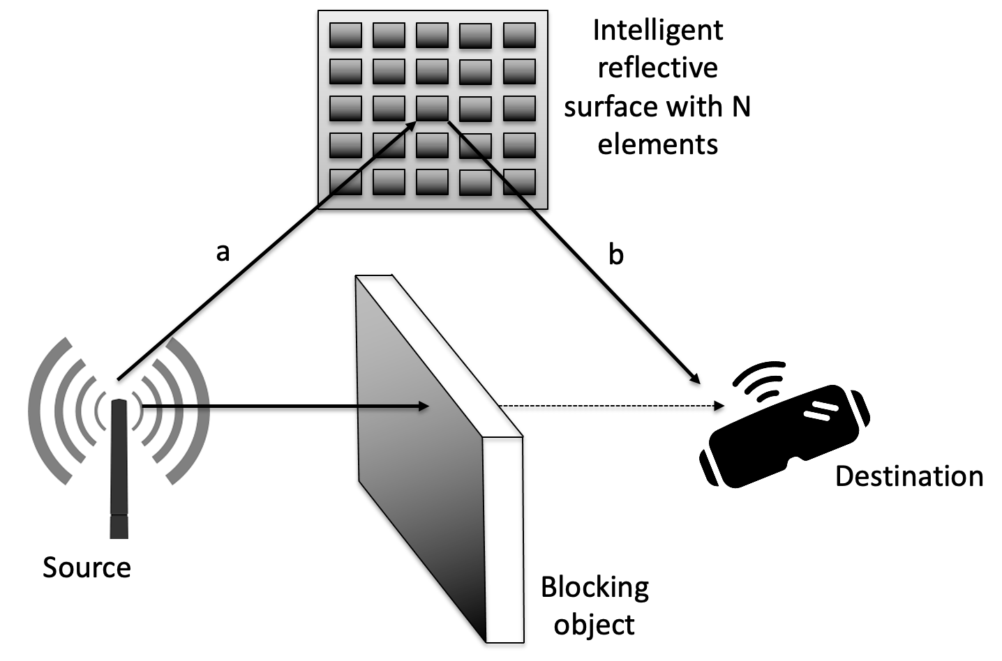
We consider the setup in Figure 1, focusing on the channel controllable by the IRS and ignoring the direct LoS between the source and the destination. We assume lossless beam-forming operation [15] for IRS-supported NLoS avoidance. A square-shaped IRS has been selected for simplicity, while the generalization to rectangular shapes can be done by iterating through the antenna elements along X and Y-axes. For each IRS element, we assume that the transmitted signal will be transmitted to the IRS through a Linear Time-Invariant (LTI) channel represented by an impulse response , where is the nth antenna element of a square-shaped IRS. When the signal reaches the element , it is reflected and, therefore, irradiated again. The signal re-radiated by each element that forms the IRS is radiated to the destination through another LTI channel with an impulse response . The joint impulse response is the convolution of the impulse responses for each IRS element [7]. Considering the above, the SNR at the IRS-supported communication link between the source and the destination can be written as [16]:
| (1) |
where , , and are the transmit power, utilized bandwidth, and the power of the additive white Gaussian noise at the destination, respectively. Equation 1 suggests that the SNR grows with when using the IRS that is optimally configured [16]. The values of and can be derived from the following (cf., [16]):
| (2) |
| (3) |
where is the free-space channel gain, , , and are the positions of respectively the source, destination, and the IRS located at the -plane and centered at .
Based on [16], we consider a lossless isotropic antenna located at that transmits a signal polarized in direction when traveling in direction. The receiver is located in the -plane centered at and has the area . The free-space channel gain follows as:
| (4) |
where and [16]. This equation is only true when the antenna area is significantly smaller compared to the wavelength, which is the case for the assumed IRS.
To calculate and , we analyze the position of the IRS with respect to the source and the destination. Without any loss of generality, we assume the source is at the distance at angle , while the destination is at distance in angle with respect to the IRS. The position of the source is, therefore, equal to and that of the destination . The location of each antenna element, expressed by its coordinates and for , is then given as:
| (5) |
| (6) |
where is the total number of elements in the IRS and the area of each element.
II-B Mobile Relay
The MR, like the IRS, is in charge of maintaining the LoS path from the source to the destination. The most common retransmission strategies include Decode-and-Forward (DF), and Amplify-and-Forward (AF). The DF MR decodes and remodulates the received signal, and retransmits it towards the destination, while the AF MR solely amplifies the received signal in a way that is transparent to the destination, and retransmits it without decoding it [17, 18]. The MRs operate in half duplex, which means that the reception and transmission are separated in time. Currently, full duplex MR capable of receiving and transmitting simultaneously are emerging [18, 19]. In this article, we are nonetheless going to focus on the use of DF MR that operates in the half-duplex mode.
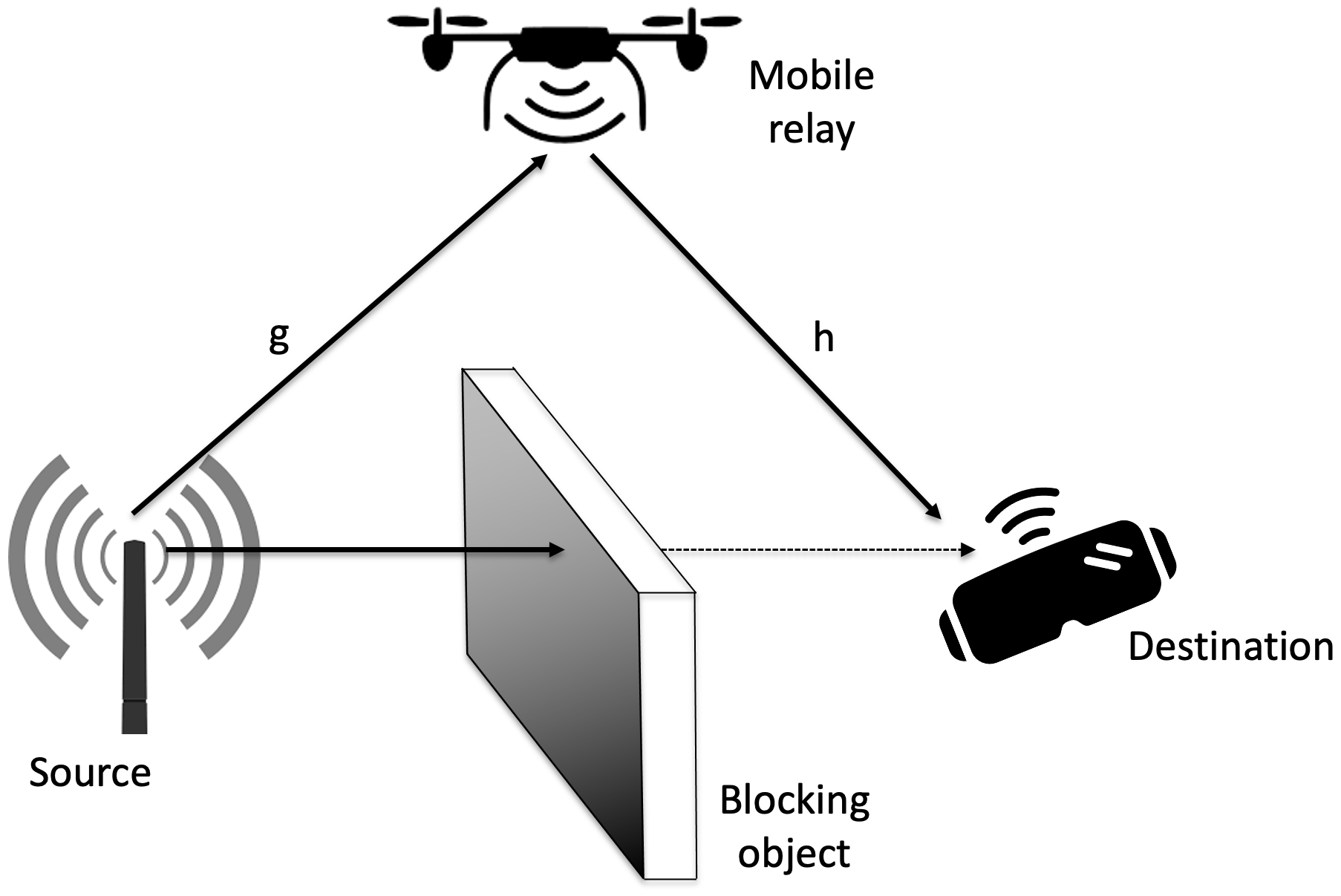
The transmission with this type of MR is carried out in two phases, first from the source to the MR, followed by the retransmission from the MR to the destination, assuming no LoS transmission [17]. Therefore, the SNR from the source to the MR, as well as the SNR from the MR to the destination, can be expressed using respectively Equations (7) and (8), while the SNR that corresponding to the end-to-end communication link can be expressed as .
| (7) |
| (8) |
In the above, represents the channel from the source to the MR, represents the channel from the MR antenna to the destination, while is the noise at the destination [16]. In this case, the SNR grows with the number of antenna elements [16, 20]. The channel gain for and can be expressed by:
| (9) |
where is equal to , is the distance between two directly communicating devices, while is the angle between the source and the destination from the MR perspective. To calculate the position of the source and the destination with respect to the MR, we follow the same principle as before for the IRS-supported NLoS avoidance.
III System Analysis
Our motivating scenario comes from the domain of full-immersive multi-user VR systems such as the one presented in [2], in which directional mmWave beams are expected to “track” the users’ movements for maintaining LoS connectivity, hence maximizing the quality of video delivery. However, the users could block their own LoS links with their bodies or they could be interrupted by the other users. In such cases, we envision the NLoS avoidance to be supported through the utilization of either the IRS or MR.
In the analysis of the IRS- and MR-supported NLoS avoidance, we assume the environment is defined as a square of a certain size. In the first scenario, we assume the IRS can be placed on any of the outer walls in the environment, so in our scenario the IRS could be positioned anywhere on the sides of the square, while the floor and the ceiling have not been considered for simplicity. In the second scenario, the MR will be utilized for NLoS avoidance, where we assume the MR can be placed anywhere in the environment. We assume both the IRS and the MR to be placed in a 2D environment, however also accounting for the height of the IRS in the derivation of the communication link quality indicators.
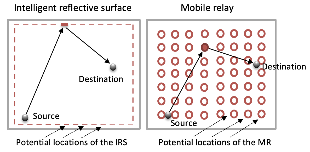
These two scenarios are depicted in Figure 3, jointly with the indication of the potential positions of the IRS and MR. To calculate the optimal position of the IRS for a particular position of the source and the destination, the SNR is calculated for all of the potential positions of the IRS on the four walls of the environment with respect to the source and the destination. To specify the set of positions the IRS could take, we utilize the approach of exhaustively iterating along the four walls of the environment with an arbitrary step distance. To calculate the optimal position of the MR for a specific position of the source and the destination, the SNR is calculated as in the previous scenario for a grid-like constellation of possible MR positions, where the distance between two neighboring potential positions features the same arbitrary step distance.
The SNR of the communication link between the source and the destination at each location of the IRS or MR can be calculated using Equations 1, 7, and 8, which take their ground from [16, 7]. The derivation of the optimal locations of the IRS and MR is based on the calculation of the SNR for all potential positions of the IRS and MR. For each source and the destination pair, the position with the highest SNR is considered as the optimal position of the IRS and MR. The only difference in the IRS- and MR-focused scenarios, apart from the approach for calculating the SNR, is that for the MR the entire environment is to be considered, while for the IRS positioning only the four outer walls of the environment are considered as feasible.
IV Evaluation Results
IV-A Evaluation Setup
In this section, we outline the simulation approach and setup used for establishing and comparing the link quality of IRS- and MR-supported NLoS avoidance in indoor mmWave networks. Given that we envision the utilization of mmWave frequencies in the range between 30 and 100 GHz [21, 22], we have selected 30 GHz as the operating frequency. As such, the communication wavelength was set to 0.01 m. Based on [23], the noise figure was set to 6 dB, antenna gain at the source to 6 dBi, and communication bandwidth to 1.76 GHz. Moreover, we have considered an additive white Gaussian noise affecting the communication performance of both IRS and MR-based setups, whose power equals to , where B is the communication bandwidth [24] and is the noise figure.
The simulation environment was assumed to be a square with sizes of , and m2, with the objective of simulating three spaces that correspond to real scenarios. Specifically, we aimed at mimicking an apartment room corresponding to the size of m2, while an office and a conference room would correspond to and m2.
The area of each antenna element was set to , where the side length of each element equals [16]. Moreover, we have considered three sets of antenna elements for both the IRS- and MR-based scenarios, with the numbers of antenna elements equaling to 100, 400, and 900. The reason for considering different numbers of antenna elements was to assess the benefits of increasing antenna array sizes on the performance in the IRS- and MR-supported NLoS avoidance. The above numbers of antenna elements for IRS-supported communication have been selected according to the existing literature, e.g., [18]. The same numbers have been utilized for MR-supported communication for supporting objective comparison between the two scenarios, ignoring the practicality of utilizing large numbers of antennas by the MR.
The complete analysis has been carried out over 10,000 simulation runs. In each run, the locations of the source and destination have been randomly defined in the environment. This was followed by deriving the optimal locations of the IRS and MR by utilizing the iterative approach presented in Section III. Specifically, for the IRS-based scenario the optimal location search space consisted of the four outer walls of the specified environments, with the granularity of the neighboring potential locations (i.e., step distance) equaling 10 cm. For the MR-based scenario, the location search space was constrained to the interiors of the specified environments, with the granularity of the neighboring locations again equaling 10 cm.
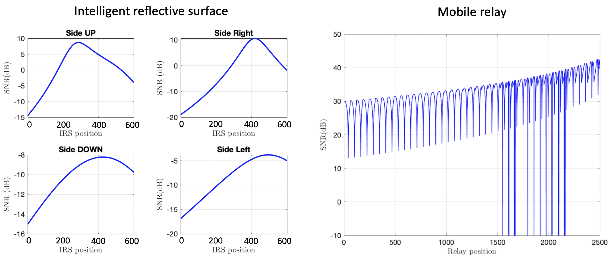
An example derivation of the optimal positions of the IRS and MR for a single position of the source and the destination is given in Figure 4. As visible in the figure, for the IRS-based scenario where the optimal location search space is constrained to the outer walls of the simulation environment, the optimal location of the IRS (i.e., the one that maximizes the SNR of the communication link between the source and the destination) is found to be on the right wall of the environment. Similarly, for the MR-based scenario the optimal location search space is specified in a grid-like fashion across the entire simulation environment, while the optimal location is the one that yields the highest SNR of the communication link. This is with the exception of the potential relay locations at which the SNR of the communication link was higher than the SNR of the direct LoS communication between the source and destination. In such cases, the SNR of the communication link through the MR is considered to be infeasible, hence these locations have been discarded by setting the corresponding SNR to -10 dBm, as visible in the figure.
IV-B Evaluation Results
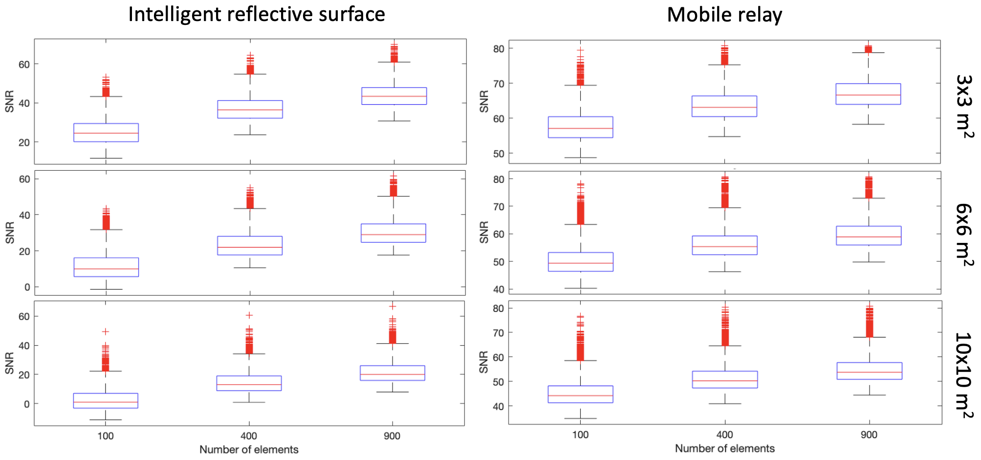
The communication quality for the IRS- and MR-supported NLoS avoidance in the considered scenarios, characterized using the average SNR over 10,000 simulation runs, is depicted in Figure 5. The obtained SNRs are depicted in the standard box-plot fashion for different environment sizes and numbers of antenna elements, as indicated in the figure. For the environment sizes of m2 and assuming the IRS-supported communication, it can be observes that the maximum SNR increases by approximately 40 and 80% when the number of IRS antenna elements increases from 100 to 400 and from 100 to 900, respectively. Assuming the MR-supported communication, the figure shows that the average SNR increases approximately 10% when the number of antennas increases from 100 to 400, and approximately 18% when the number of antennas increases from 100 to 900.
Similar observations can be made for different environment sizes. Specifically, if we analyze the environment with sizes of m2 and assuming the IRS-supported communication, there is an approximate 50% increase in the average SNR quality when increasing the number of antenna elements from 100 to 400, as well as an additional 30% increase when the number of antenna elements is increased from 400 to 900. For MR-supported communication, the average SNR increases by respectively 10 and 20% if the number of antenna elements is increased from 100 to 400 and 900. For the environment with sizes of m2 and the IRS-supported communication, an approximate increase of 8 dB is observed when increasing the number of antenna elements from 100 to 400 and an additional one of 10 dB if the increase is from 400 to 900 elements. When the MR is used with 400 antenna elements, an increase is approximately 5 dB, while with 900 antennas approximately 10 dB compared to the antenna array of 100 elements.
When comparing the communication link performance as a function of the sizes of the considered environments, it can be observed that the increase in the sizes of the environment degrades the average quality of the communication links. For example, when utilizing the IRS with 100 antenna elements the average SNR is reduced with respect to the m2-sized environment by 32% and 55% as the environment sizes increase to respectively m2 and m2. Similarly, the average SNR is reduced with respect to the m2-sized environment by 34% and 12% with the use of the MR. Similar trends can be observed for different configurations pertaining to the number of utilized antenna elements in both IRS and MR-supported communication, as visible in Figure 5.
Based on the derived results, we can observe that the MR generally yields significantly better communication performance than the IRS, with the average improvement of roughly 20 dB observed along all parameterizations of the scenario of interest. We argue the reason can be found in the fact that the MR actively retransmits the signals, while the IRS passively reflects them with phase-shifts. Moreover, the MR features a higher degree of freedom in terms of its optimal positioning in the environment of interest. Due to that, the average distance that signals have to traverse between the source and destination are lower for MR-supported communication compared to its IRS-supported counterparts.
Besides that, our results demonstrate that, if the design goal is to guarantee a certain link quality of an indoor mmWave communication system in NLoS conditions using the IRS or MR, the sizes of the environment should be taken into account jointly with the number of antenna elements deployed at the IRS or MR level. In other words, increasing the number of antenna elements will be needed for coping with the signal attenuation at mmWave frequencies due to the increased communication ranges stemming from the increase in the sizes of the environment. Finally, our results also motivate the need for optimal positioning of the IRS or MR for optimizing the communication quality between the source and the destination. The motivation for that can be found in Figure 4 demonstrating that the quasi-optimal positioning (i.e., optimal for the given granularity between potential locations of the IRS and MR) of both the IRS and MR can increase the SNR of communication by more than 25 dB compared with the worst case scenario.
V Conclusion
We have considered the Intelligent Reflective Surfaces (IRSs) and Mobile Relays (MRs) as potential technologies for mitigating the negative effects of Non-Line-of-Sight (NLoS) connectivity in indoor mmWave networks. Accounting for the characteristics of this specific setup, the MRs achieve significantly higher average Signal-to-Noise Ratio (SNR) of communication than the IRSs. This is a direct consequence of the higher degree of freedom of movement that the MRs feature compared to the IRSs. Nonetheless, one should realize that the IRSs have intrinsic advantages that could make them preferable to the MRs, such as their lower cost and higher energy efficiency. Therefore, our indications currently only pertain to the communication quality indications and are tightly related to the freedom of positioning of the IRSs and MRs. Future work will be focused on deriving a comparison framework that is able to capture different performance metrics including production and maintenance costs, energy consumption, communication reliability and latency. We will also consider utilizing a faster optimization approach for IRS and MR positioning than the exhaustive search, as well as 3D environments and scenarios with multiple users. Finally, in this work we have assumed that the MRs can instantaneously reach their optimal positions, which will in reality incur a certain delay, effectively reducing the throughput of communication. Therefore, part of the future work will be focused on incorporating such delays in the MR-focused scenario and capturing their effects on the performance of MR-supported NLoS avoidance in mmWave communication.
Acknowledgments
Filip Lemic was supported by the EU H2020 Marie Skłodowska-Curie project ”Scalable Localization-enabled In-body Terahertz Nanonetwork” (nr. 893760).
References
- [1] Marco Di Renzo “Reconfigurable intelligent surfaces vs. relaying: Differences, similarities, and performance comparison” In IEEE Open Journal of the Communications Society 1 IEEE, 2020, pp. 798–807
- [2] Jakob Struye “Millimeter-Wave Beamforming with Continuous Coverage for Mobile Interactive Virtual Reality” In arXiv preprint arXiv:2105.11793, 2021
- [3] Lin Chen and Ying Huang “Mobile relay in LTE-advanced systems” In IEEE Communications Magazine 51.11 IEEE, 2013, pp. 144–151
- [4] Balaji Raghothaman “System architecture for a cellular network with cooperative mobile relay” In Vehic. Tech, 2011, pp. 1–5 IEEE
- [5] Filip Lemic “Location-based mechanism for positioning of a mobile relay” In ACM Symposium on QoS and Security for Wireless and Mobile Networks, 2017, pp. 73–80
- [6] Ken Mendes, Jeroen Famaey and Filip Lemic “Small UAVs-supported Autonomous Generation of Fine-grained 3D Indoor REMs” In Wireless Sensor, Robot and UAV Networks (WiSARN), 2022 IEEE
- [7] Emil Björnson “Reconfigurable Intelligent Surfaces: A signal processing perspective with wireless applications” In IEEE Signal Processing Magazine 39.2 IEEE, 2022, pp. 135–158
- [8] Christos Liaskos “A new wireless communication paradigm through software-controlled metasurfaces” In IEEE Communications Magazine 56.9 IEEE, 2018, pp. 162–169
- [9] Qingqing Wu “Intelligent reflecting surface aided wireless communications: A tutorial” In IEEE Transactions on Communications IEEE, 2021
- [10] Emil Björnson “Intelligent reflecting surface versus decode-and-forward: How large surfaces are needed to beat relaying?” In IEEE Wireless Communications Letters 9.2 IEEE, 2019, pp. 244–248
- [11] Giorgos Stratidakis “An analytical framework for Reconfigurable Intelligent Surfaces placement in a mobile user environment” In ACM Embedded Networked Sensor Systems, 2021, pp. 623–627
- [12] Qingqing Wu and Rui Zhang “Towards smart and reconfigurable environment: Intelligent reflecting surface aided wireless network” In IEEE Communications Magazine 58.1 IEEE, 2019, pp. 106–112
- [13] Filip Lemic “Localization in power-constrained Terahertz-operating software-defined metamaterials” In ELSEVIER Nano Communication Networks 30 Elsevier, 2021, pp. 100365
- [14] Xiaojun Yuan “Reconfigurable-intelligent-surface empowered wireless communications: Challenges and opportunities” In IEEE Wireless Communications 28.2 IEEE, 2021, pp. 136–143
- [15] Haseeb Ur Rehman “Joint Active and Passive Beamforming Design for IRS-Assisted Multi-User MIMO Systems: A VAMP-Based Approach” In IEEE T. on Communications 69.10 IEEE, 2021, pp. 6734–6749
- [16] Emil Björnson “Power scaling laws and near-field behaviors of massive MIMO and intelligent reflecting surfaces” In IEEE Open Journal of the Communications Society 1 IEEE, 2020, pp. 1306–1324
- [17] Georgy Levin “Amplify-and-forward versus decode-and-forward relaying: Which is better?” In International Zurich seminar on communications, 2012 Eidgenössische Technische Hochschule Zürich
- [18] Emil Björnson, Özgecan Özdogan and Erik G Larsson “Reconfigurable intelligent surfaces: Three myths and two critical questions” In IEEE Communications Magazine 58.12 IEEE, 2020, pp. 90–96
- [19] Le Van Nguyen “Closed-form expression for the symbol error probability in full-duplex spatial modulation relay system” In Sensors 19.24 Multidisciplinary Digital Publishing Institute, 2019, pp. 5390
- [20] CH Lee “Large-array signal processing for deep-space applications” In Interplanetary Network Progress Report, 2002, pp. 1–28
- [21] Rauful Nibir “Quintuple Band Antenna Design Using Stacked Series Array For Millimeter Wave” In International Telecommunication Networks and Applications (ITNAC), 2020, pp. 1–6 IEEE
- [22] Xi Lu “Integrated use of mmWave radio technology in 5G and beyond” In IEEE Access 7 IEEE, 2019, pp. 24376–24391
- [23] Rui Wu “64-QAM 60-GHz CMOS transceivers for IEEE 802.11ad/ay” In IEEE J. of Solid-State Circuits 52.11 IEEE, 2017, pp. 2871–2891
- [24] Konstantinos Ntontin, Jian Song and Marco Di Renzo “Multi-antenna relaying and reconfigurable intelligent surfaces: End-to-end SNR and achievable rate” In arXiv:1908.07967, 2019