Send correspondence to A. Vigan (arthur.vigan@lam.fr).
Connecting SPHERE and CRIRES+ for the characterisation of young exoplanets at high spectral resolution: status update of VLT/HiRISE
Abstract
New generation exoplanet imagers on large ground-based telescopes are highly optimised for the detection of young giant exoplanets in the near-infrared, but they are intrinsically limited for their characterisation by the low spectral resolution of their integral field spectrographs (). High-dispersion spectroscopy at would be a powerful tool for the characterisation of these planets, but there is currently no high-resolution spectrograph with extreme adaptive optics and coronagraphy that would enable such characterisation. With project HiRISE we propose to use fiber coupling to combine the capabilities of two flagship instruments at the Very Large Telescope in Chile: the exoplanet imager SPHERE and the high-resolution spectrograph CRIRES+. The coupling will be implemented at the telescope in early 2023. We provide a general overview of the implementation of HiRISE, of its assembly, integration and testing (AIT) phase in Europe, and a brief assessment of its expected performance based on the final hardware.
keywords:
High-contrast imaging, High-spectral resolution, High-dispersion coronagraphy, VLT, Exoplanet, Characterisation, Spectroscopy1 INTRODUCTION
Direct imaging allows to spatially separate and directly measure radiation from an exoplanet, which enables the spectral analysis of its atmosphere with minimized impact from the host star. Direct imagers such as SPHERE[1], GPI[2], and SCExAO[3] are designed to find and detect young planets around nearby stars[4, 5, 6], which can be used to study the population of young giant exoplanets through large direct imaging surveys[7, 8, 9, 10]. However, current instruments are limited for the characterization of companions by their spectral resolution of at most[11].
High-dispersion spectrographs have been used to detect the thermal radiation of various giant exoplanets by relying on the large number of molecular lines detectable in the atmospheres of these planets, which can only be accessed at spectral resolutions above a few 10 000s. Important results have been obtained on both transiting and non-transiting planets[12, 13, 14], as well as on spatially resolved low-mass companions[15, 16, 17]. For the latter, the most well-known case is that of the directly-imaged exoplanet Pictoris b[15] using the CRIRES instrument[18] on the ESO Very Large Telescope (VLT). This method has since provided more atmospheric detections and rotation speeds of young directly imaged companions[16, 17, 19], providing unique insight into the properties of this population of objects[19].
Measurements on young companions have been obtained with low-order adaptive optics systems like MACAO[20] for the Pictoris b result. With such systems, the atmospheric turbulence correction concentrates a moderate fraction of the energy in the PSF core (typically 50–60% in the band[21]), but the level of the uncorrected halo is high. This means that the strongest limiting factor of the signal-to-noise ratio (S/N) of the planet signal close to the star remains the noise contributed by the uncorrected stellar halo. To significantly decrease the halo, it is necessary to rely on high-order adaptive optics known as extreme adaptive optics (ExAO), which can provide diffraction-limited images in the near-infrared (NIR) and therefore decrease the level of stellar halo (and noise) at the location of the planet[22, 23, 24, 25, 26]. Diffraction-suppressing coronagraphs can also be used to further improve the contrast and decrease the level of stellar residuals at the location of the planet.
Until recently, no instrument dedicated to high-contrast imaging was equipped with means of characterizing detected companions at very high spectral resolutions. Conversely, none of the existing high-resolution spectrographs in the near infrared is equipped with either an ExAO system or with a coronagraph, which would facilitate the characterization of known companions. In recent years, several projects have proposed combining ExAO systems with existing mid- or high-resolution spectrographs using single-mode fibers (SMF) either in the NIR, for example between NIRC2 and NIRSPEC at Keck (KPIC)[27, 25] or between SCExAO and IRD at Subaru (REACH)[28, 22, 29], or in the visible, for example between SPHERE and ESPRESSO at the VLT[30]. For the NIR, the VLT offers a unique opportunity to achieve a similar feat by coupling the high-contrast imager SPHERE[1] with the recently upgraded high-resolution spectrograph CRIRES+[31], which are now both available at the VLT/UT3. The coupling between these two flagship instruments has been proposed as the High-Resolution Imaging and Spectroscopy of Exoplanets project (HiRISE)[26, 32].
SPHERE offers a unique ExAO system (SAXO)[33] that has demonstrated exquisite performance on-sky[34, 35, 36] and efficient coronagraphs[37, 38]; its infrared arm covers the , , , and bands. CRIRES+ is a refurbished and upgraded version of the CRIRES spectrograph[18], operating in the , , , , , and bands (0.9-5.3 ) at resolving power with a 0.2′′-slit. It features three Hawaii-2RG 2k2k detectors and a cross-disperser to cover more than 50% of the band in a single observation. The large overlap in terms of spectral coverage between SPHERE and CRIRES+ is a key advantage in particular in the and bands, which contain strong molecular features for CO, CH4, H2O, or NH3. The high angular resolution and high-contrast capabilities of SPHERE at these wavelengths, combined with the high spectral resolution of CRIRES+, will provide a unique system capable of characterizing known directly imaged companions.
2 IMPLEMENTATION
2.1 Overview
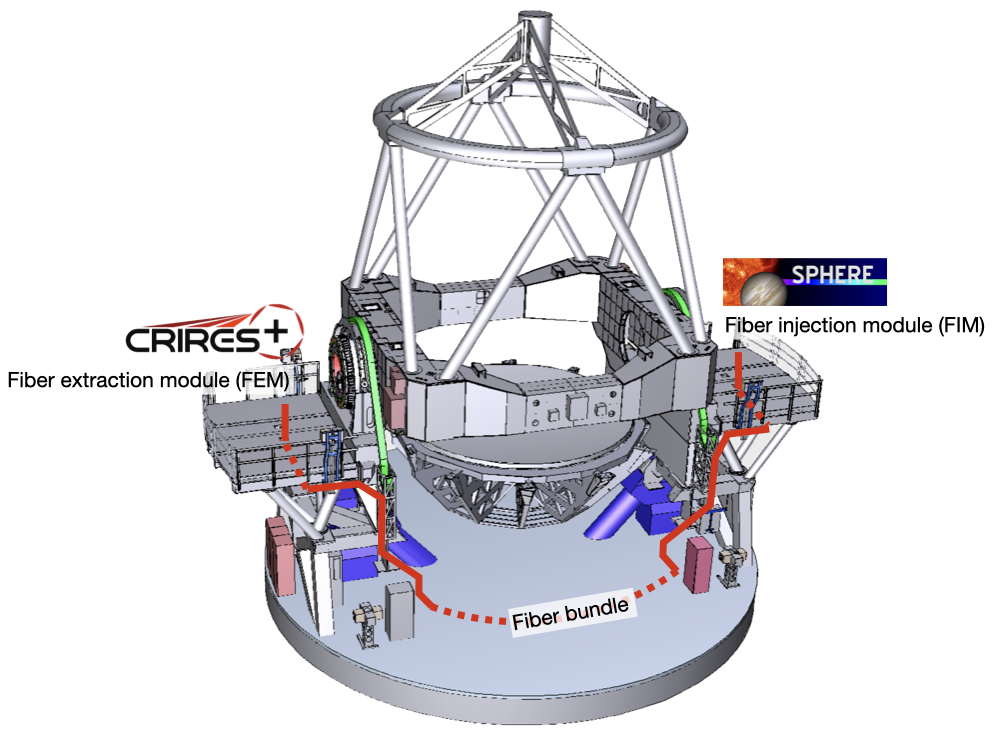
The HiRISE coupling will be implemented on the VLT-UT3 between SPHERE and CRIRES+, which are located on Nasmyth platforms A and B, respectively. This is illustrated in Fig. 1. The system consists in three main sub-systems:
-
1.
the fiber injection module (FIM) implemented inside of SPHERE. The role of the FIM is to pick-up the SPHERE scientific beam and inject the signal of a known exoplanet in a science fiber. The FIM will be described in Sect. 2.2;
-
2.
the fiber bundle that connects SPHERE and CRIRES+ around the telescope. The bundle transmits the planetary and stellar signals up to the entrance of the spectrograph. The bundle will be described in Sect. 2.3;
-
3.
and the fiber extraction module (FEM) implemented inside of CRIRES+. The role of the FEM is to reimage the output of the bundle’s fibers in the VLT focal plane with the appropriate focal ratio. The FEM will be described in Sect. 2.4;
In addition to these main sub-systems, HiRISE also includes a dedicated electronics cabinet located on the SPHERE Nasmyth platform, and a dedicated control software developed following the VLT Software standards. These additional components will be described in Sect. 2.5.
2.2 Fiber injection module
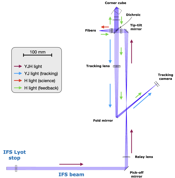
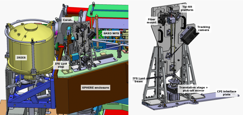
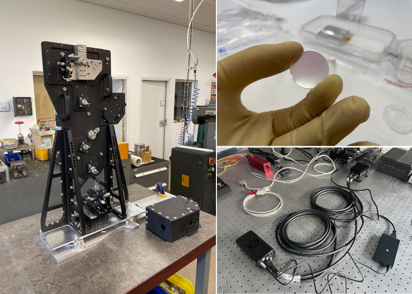
The FIM is an additional sub-system implemented inside of the SPHERE enclosure, on the main CPI bench. It diverts the beam of the SPHERE/IFS towards a dedicated optical bench. The optical design with photon sharing is presented in Fig. 2 and the mechanical implementation is presented in Fig. 3. Images of the final hardware being integrated or tested in the lab are presented in Fig. 4.
Originally, the VLT/HiRISE system has been proposed for both the and bands[26]. However, following the simulation study presented in [32], the expected performance in -band was considered to be insufficient to justify the added complexity of implementing the band in the system. Most of all, the band requires the use of ZBLAN fibers that provide a high-tranmission at wavelengths longer than 1.6 , which corresponds to the typical wavelength cutoff of pure silica fibers. However, ZBLAN fibers are expensive and not easy to handle without suffering damages. Moreover, few industrial companies are ready to accept the risk to work with this type of fibers for manufacturing a long fiber bundle such as the one required for HiRISE. For these reasons, we decided to drop support for the band and focus only on the band using a pure silica fiber, reference 1310M-HP, manufactured by Coherent (formerly Nufern).
In the FIM, the pick-off mirror is immediately followed by a relay lens that reimages the telescope pupil on a piezo tip-tilt stage. This tip-tilt is used to move the focal-plane image with respect to the fiber bundle and the tracking camera. The beam is (almost) recollimated by a custom cemented doublet, and then a custom dichroic filter designed and manufactured by the Fresnel institute111https://www.fresnel.fr/ that splits the wavelengths between the tracking channel (0.95–1.2 ) and the science channel (1.4–1.8 ). Finally, an air-gap doublet is used to reimage the focal-plane at F/3.5 on top of the science fibers in the bundle. F/3.5 does not exactly match the F-number expected by fibers (NA=0.16; F/3.3), but adopting a slightly larger value was mandatory to free some physical space for the mechanical implementation of the system. In the tracking channel, a doublet reimages the focal plane on the tracking camera, a C-RED 2 from First Light Imaging, with an focal ratio of F/40. The images on the tracking camera are Nyquist-sampled starting at 0.95 .
A retro-injection channel is included in the system to emit light from calibration fibers included in the fiber bundle and reimage them on the tracking camera on top of the astrophysical scene. These calibration fibers will be used for the acquisition procedure to center the planet’s PSF on the science fiber, as detailed in [39]. Because the beam is not exactly collimated at the level of the dichroic filter, a corrector plate with a very long focal length was added in front of the corner cube to compensate for the small additional length between the dichroic and corner cube. The wavelength of the calibration source is at 1.3 , i.e. in the transition region of the dichroic filter.
The system is implemented on a vertical bench above the SPHERE/IFS beam. The pick-off mirror is introduced in the beam with an OWIS precision translation stage, which will be controlled from the SPHERE control software. Most mechanical parts are custom made from aluminum or Invar 36, manufactured by the mechanical workshop at the Georg-August-Universität in Göttingen. The other parts are off-the-shelf components from Thorlabs and Newport. The optics are a mix between off-the-shelf lenses and mirrors from Thorlabs and Edmund, and custom optics manufactured by Optique Fichou222https://www.optique-fichou.com/ (France).
The fiber bundle will be held in a multi-axis fiber optic positioner from Newport using a custom interface piece. The multi-axis positioner will be used for the fine positioning of the bundle with respect to the injection optics. The focus and tip and tilt of the bundle were used as compensator in the tolerancing analysis of the optical design, so these degrees of freedom are essential for a fine alignment of the system.
2.3 Fiber bundle
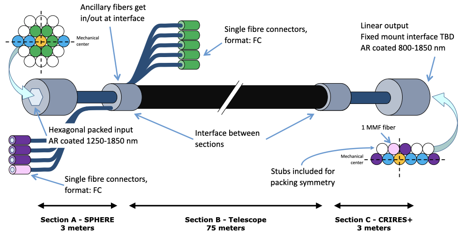
A schematic of the proposed design for the fiber bundle is presented in Fig. 5. The bundle is a single piece of hardware composed of three main sections. It features four science fibers (one dedicated to the planet) and ancillary fibers for calibration purposes. The bundle will be manufactured by Fibertech Optica333https://fibertech-optica.com/ (FTO) in Canada.
Section A is located on the SPHERE side and has a length of 3 m. Most of its length is located inside of the SPHERE enclosure. A part of section A is located outside of the enclosure because the ancillary calibration fibers get in/out of the bundle at the level of the interface between section A and B, and they connect to calibration sources located inside the HiRISE electronics cabinet. The input of the bundle features an hexagonal pattern of fibers that includes the four science fibers, one fiber connected to a fluxmeter, and four retro-injection fibers connected to a calibration source at 1.3 . The purpose of these five calibration fibers is further described in [39]. The input of the bundle will be directly AR-coated with a coating covering both the science and calibration wavelengths.
Section B is the long section of the bundle that goes around the telescope structure. It is more heavily protected because it will be exposed to the harsh environment of the telescope where it can be crushed or stepped on. It includes a central glass rod and a tensile element to maintain the length, minimize the mechanical stresses on the fibers inside, and protect the fibers from breaking. The route around the telescope has been investigated by the Paranal observatory and a steel cable has been pulled all the way to verify the routing feasibility and measure the exact length (75 m).
Finally, section C is located on the CRIRES+ side and has again a length of 3 m. In the output ferrule, the fibers are arranged in a double line. The main line includes the four science fibers plus two external calibration fibers that will be used during AIT; this line of fibers will be aligned along the slit of the spectrograph. The second line includes two calibration fibers, which will be used for the MACAO system to maintain the deformable mirror flat during the HiRISE observations. One of the two calibration fibers is a SMF identical to the science fibers, and the other is a multi-mode fiber (MMF) with a 50 core. Again, the output of the bundle will be directly AR-coated with a coating covering both the science and calibration wavelengths.
The interface parts between sections A, B and C have been specified to minimize impact during the installation of the bundle at the telescope. For the installation, it is foreseen to start the routing on the SPHERE side, which has both the main bundle and ancillary fibers, and then route section B and C step-by-step around the telescope. It was originally proposed to have connectors at the interfaces between sections to make the installation easier, but designing connectors with losses lower than 0.2 dB revealed to be extremely risky and costly, and the final level of losses could not be guaranteed.
2.4 Fiber extraction module
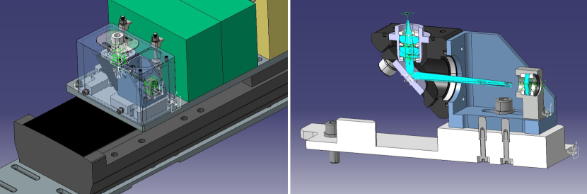
The FEM is implemented on the carrier stage unit (CSU) of the warm bench of CRIRES+. It is used to reimage the output of the science and calibration fibers in the VLT focal plane at F/15, which is the focal ratio expected by CRIRES+ for direct observations with the VLT. The opto-mechanical implementation of the FEM on the CSU is presented in Fig. 6.
Compared to the FIM, the FEM is a much simpler system with no active device to be controlled. Its role is to simply reimage the fibers in the VLT focal plane. To make the installation easier and avoid unnecessary bending of the fibers, a folding mirror is implemented in the FEM so that the bundle’s ferrule is simply inserted vertically at the top of the FEM. Since it is installed in the visitor gas cell slot of CRIRES+, the FEM must be easily removable in a matter of minutes. It is held in place by 3 screws that can be accessed without removing the cover. The FEM can then be put back in place quickly using a set of calibrated shims and the precision pins available on the CSU.
The FEM does not include active elements, but it must be able to deal with the MACAO adaptive optics system of CRIRES+, which is located downstream in the optical train. One of the difficulties of the MACAO system is that its deformable mirror cannot be maintained flat in open-loop on the timescale of hours, which are foreseen for the observations with HiRISE. To cope with that limitation, the fiber bundle include two calibration fibers (1 SMF, 1 MMF) located nearby the science fibers, which will be fed by a broadband source and will serve as an AO guide star for the MACAO system. Only one of the two will be used, but to keep some flexibility two different types of fibers were included in the design of the bundle: the SMF will be totally unresolved so that it truly resembles a stellar object, but the transmitted flux might be too low for MACAO; the MMF will be slightly resolved with its large 50 core, but it will provide a much higher flux. The two options will be tested during the commissioning.
2.5 Electronics and control
The FIM in HiRISE includes several active and passive devices, which must be interfaced with the HiRISE workstation for operating the system. All the controllers are located in the HiRISE electronics cabinet (HiCab), which will be installed underneath the SPHERE instrument on the Nasmyth platform. To simplify the implementation, the HiRISE workstation is directly embedded within the HiCab in the form of an industrial computer running VLT Software (CentOS Linux 7.7 + VLT common software 2020).
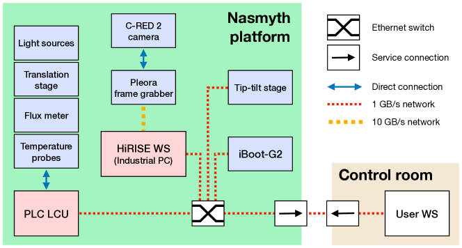
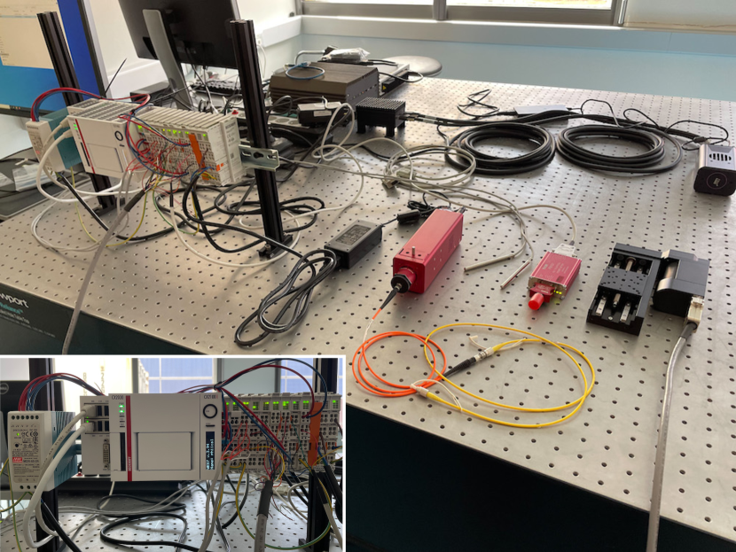
The HiRISE workstation is connected to the devices and sensors through different means (Fig. 7). The iPORT frame grabber from Pleora Technologies is connected to the workstation using a dedicated 10GB/s network interface and short-range optical link. The tip-tilt stage controller (E272 from PI) and the connected power switch (iBoot-G2) are connected on the private HiRISE instrument network through a Cisco switch. Finally, the other devices and sensors are connected to a Beckhoff PLC computer, which is itself connected to the private HiRISE network to be accessible from the workstation. Pictures of the hardware in the integration clean room at LAM are presented in Fig. 8.
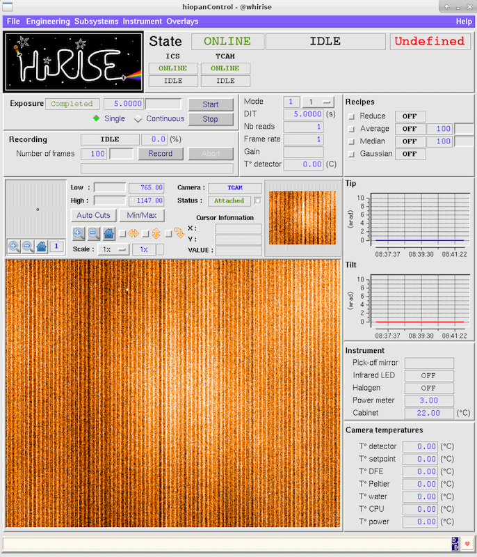
Finally, a dedicated control software and interface is in development for the control of the system. The main interface is presented in Fig. 9. The HiRISE control software follows the same logic and organization as all VLT instruments in order to make the future operations as transparent as possible for the observatory staff. In particular, it is foreseen to develop dedicated templates for the main calibrations of FIM, as well as for the target centering, which corresponds to the accurate placement of the planet’s PSF on the science fiber. The target (star) acquisition will be performed by the SPHERE system, and the scientific data acquisition by the CRIRES+ system.
3 EXPECTED PERFORMANCE
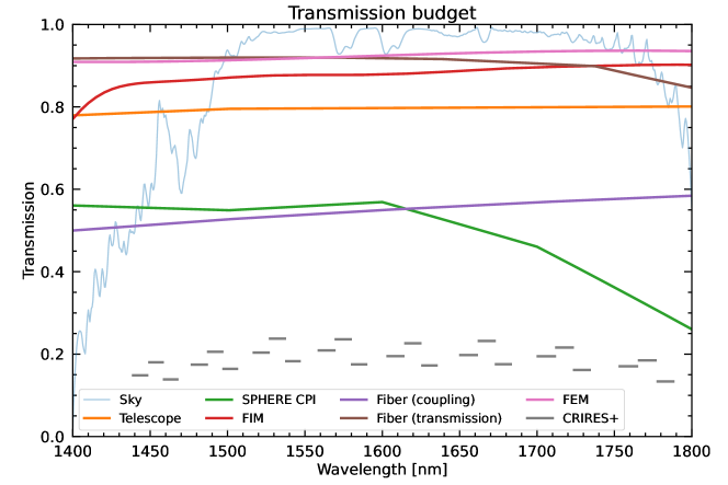
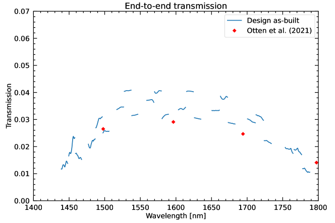
The end-to-end simulations of [32] have clearly demonstrated that the final detection performance of HiRISE is driven by the overall transmission of the system. The transmission budget has been updated based on the final optical components and AR coatings. The complete budget is presented in Fig. 10.
For SPHERE and CRIRES+ we rely on values that have been measured either in the lab or on sky, which have been kindly provided by the two instrument consortia. For the lenses in the FIM and the FEM, we use the AR coatings information provided by the optics manufacturers. For the mirrors, purchased from Edmund, we use a value 0.98 for the reflectivity at all wavelengths.
One of the important budget contributors is the fiber bundle, and in particular the coupling efficiency of the planet’s PSF into the science fiber. For the fused silica fiber itself, we use the attenuation values provided in [40] and scaled to the attenuations provided at 1300 and 1500 nm by Coherent for the 1310M-HP fiber (which are very slightly worse than the values from [40]). For the coupling efficiency we use the HiRISE simulation model[32] to compute the overlap integrals between the planet’s PSF electric field and the field transmitted by the science fiber. For this computation, we include ExAO residuals (for a 0.8′′ seeing), SPHERE non-common path aberrations measured with ZELDA[41, 42, 43, 44], and the wavefront errors of the FIM based on the Zemax model with as-built optics. We also include a centering error of 8 mas (0.2 at 1.6 ) on the science fiber, which corresponds to a realistic pointing error after centering the planet on the science fiber[39].
The updated transmission budget shows a small gain of 20% at 1.6 compared to the values previously reported in [32]. This is encouraging for the final performance of HiRISE, which should hopefully be better than anticipated from previous end-to-end simulations. An update of the astrophysical simulations is currently on-going in preparation for the on-sky validation. The gains are mainly due to the high quality of the AR coatings for the custom optics, the quality of the coatings for the FIM dichroic, and the use of highly transmissive fused silica fibers. The current model does not take into account the transmitance of the glasses used for the custom lenses. This may have a slight negative impact that will be evaluated in the near future.
A significant contributor to the transmission budget is the SPHERE DICH-K dichroic, which is used to send the band light to IRDIS and the bands to the IFS and HiRISE. This dichroic shows a strong decrease of its transmission starting at 1.6 , which is clearly visible in the top panel of Fig. 10. As part of the SPHERE+ project[45], an updated version of that dichroic could be considered to improve the transmission budget of HiRISE and the SPHERE IFS. Another possibility to improve the global transmission would be to switch to a dedicated fiber-fed spectrograph such as the VIPA concept[46], which recently demonstrated a transmission of the order of 40% in H-band on sky Carlotti et al. (this conference).
4 PROJECT STATUS AND SCHEDULE
HiRISE has followed a step-by-step approach for its validation by ESO. First, the science case for the instrument was submitted to ESO’s observing programmes committee (OPC) in September 2019, which expressed a strong scientific support for the project at the end of 2019 and offered the technical aspects to be evaluated by the Paranal observatory and the ESO’s scientific and technical committee (STC). Then, a visitor instrument proposal containing a full technical description was submitted to the STC in April 2020, leading to a validation by the STC and ESO’s council at the end of 2020 and the acceptance of HiRISE as a visitor instrument for the VLT. The project will now hold a final review of the project with the observatory at the end of July 2022. This final review is not a final design review in the common sense of the term but a final validation of the technical aspects and interfaces that have already been thoroughly discussed between the project and the observatory. As a result, the procurement of the hardware has already started since 2020 (from long lead-time elements) and is now almost complete.
The HiRISE project is therefore entering its main AIT phase in Europe. At the time of writing (end of June 2022), all the hardware for the FIM has been received at LAM, which is the most complex part of the whole system. The bundle is expected to be delivered by FTO in October 2022, and the mechanical parts of the FEM will start to be manufactured over the summer. A “SPHERE simulator” is currently being aligned to deliver a beam with the same properties as the SPHERE IFS beam in which the FIM will be placed. In parallel, a fine pre-assembly of the FIM and its optics will be performed using metrology. Then, the SPHERE simulator and FIM will be aligned relative to each other so that the final optical alignment of the FIM can be performed. Because the fiber bundle will arrive later in the year and because the bundle will not easily be usable to assess the optical quality, we anticipate the use of a Phasics near-infrared wavefront sensor in the injection focal plane to evaluate the optical quality of the alignment. The procedure for the validation of the full system including the bundle and the FEM is still under study.
The current schedule foresees an installation of the system at the VLT between February and March 2023. Although this schedule may shift in case of major issues during AIT in Europe, slots have already been allocated in the observing schedule for period P110. These slots will be dedicated to the installation, which requires the telescope to be put offline for some days and nights, and to the on-sky validation of the system to assess the final performance. Assuming a reasonable level of performance, scientific observations could start at the beginning of P111 in April 2023.
HiRISE is a visitor instrument, which means that it will not be offered for observations to the community as a regular facility instrument. However, anyone interested to observe with HiRISE is cordially invited to contact the project to discuss opportunities. The project anticipates the submission of a large observing programme to observe most known sub-stellar companions observable from Paranal but additional programmes in collaboration with the HiRISE project team are a highly desirable possibility.
Acknowledgements.
This project has received funding from the European Research Council (ERC) under the European Union’s Horizon 2020 research and innovation programme, grant agreements No. 757561 (HiRISE) and 678777 (ICARUS), from the Commission Spécialisée Astronomie-Astrophysique (CSAA) of CNRS/INSU, and from the Action Spécifique Haute Résolution Angulaire (ASHRA) of CNRS/INSU co-funded by CNES, and from Région Provence-Alpes-Côte d’Azur under grant agreement 2014-0276 (ASOREX).References
- [1] Beuzit, Vigan, Mouillet et al., “SPHERE: the exoplanet imager for the Very Large Telescope,” A&A 631, A155 (Nov 2019).
- [2] Macintosh, Graham, Ingraham et al., “First light of the Gemini Planet Imager,” Proceedings of the National Academy of Science 111, 12661–12666 (Sep 2014).
- [3] Jovanovic, Martinache, Guyon et al., “The Subaru Coronagraphic Extreme Adaptive Optics System: Enabling High-Contrast Imaging on Solar-System Scales,” PASP 127, 890 (Sept. 2015).
- [4] Macintosh, Graham, Barman et al., “Discovery and spectroscopy of the young jovian planet 51 Eri b with the Gemini Planet Imager,” Science 350, 64–67 (Oct 2015).
- [5] Chauvin, Desidera, Lagrange et al., “Discovery of a warm, dusty giant planet around HIP 65426,” A&A 605, L9 (Sep 2017).
- [6] Keppler, Benisty, Müller et al., “Discovery of a planetary-mass companion within the gap of the transition disk around PDS 70,” A&A 617, A44 (Sep 2018).
- [7] Vigan, Patience, Marois et al., “The International Deep Planet Survey. I. The frequency of wide-orbit massive planets around A-stars,” A&A 544, A9 (Aug. 2012).
- [8] Galicher, Marois, Macintosh et al., “The International Deep Planet Survey. II. The frequency of directly imaged giant exoplanets with stellar mass,” A&A 594, A63 (Oct. 2016).
- [9] Vigan, Bonavita, Biller et al., “The VLT/NaCo large program to probe the occurrence of exoplanets and brown dwarfs at wide orbits. IV. Gravitational instability rarely forms wide, giant planets,” A&A 603, A3 (July 2017).
- [10] Vigan, Fontanive, Meyer et al., “The SPHERE infrared survey for exoplanets (SHINE). III. The demographics of young giant exoplanets below 300 au with SPHERE,” A&A 651, A72 (July 2021).
- [11] Vigan, Langlois, Moutou & Dohlen, “Exoplanet characterization with long slit spectroscopy,” A&A 489, 1345–1354 (Oct. 2008).
- [12] Snellen, de Kok, de Mooij & Albrecht, “The orbital motion, absolute mass and high-altitude winds of exoplanet HD209458b,” Nature 465, 1049–1051 (Jun 2010).
- [13] Brogi, Snellen, de Kok et al., “The signature of orbital motion from the dayside of the planet Boötis b,” Nature 486, 502–504 (Jun 2012).
- [14] Birkby, de Kok, Brogi et al., “Detection of water absorption in the day side atmosphere of HD 189733 b using ground-based high-resolution spectroscopy at 3.2m.,” MNRAS 436, L35–L39 (Nov 2013).
- [15] Snellen, Brandl, de Kok et al., “Fast spin of the young extrasolar planet Pictoris b,” Nature 509, 63–65 (May 2014).
- [16] Schwarz, Ginski, de Kok et al., “The slow spin of the young substellar companion GQ Lupi b and its orbital configuration,” A&A 593, A74 (Sep 2016).
- [17] Hoeijmakers, Schwarz, Snellen et al., “Medium-resolution integral-field spectroscopy for high-contrast exoplanet imaging. Molecule maps of the Pictoris system with SINFONI,” A&A 617, A144 (Oct 2018).
- [18] Kaeufl, Ballester, Biereichel et al., [CRIRES: a high-resolution infrared spectrograph for ESO’s VLT ], vol. 5492 of Society of Photo-Optical Instrumentation Engineers (SPIE) Conference Series, 1218–1227 (2004).
- [19] Bryan, Benneke, Knutson, Batygin & Bowler, “Constraints on the spin evolution of young planetary-mass companions,” Nature Astronomy 2, 138–144 (Dec 2018).
- [20] Arsenault, Alonso, Bonnet et al., [MACAO-VLTI: An Adaptive Optics system for the ESO VLT interferometer ], vol. 4839 of Society of Photo-Optical Instrumentation Engineers (SPIE) Conference Series, 174–185 (2003).
- [21] Paufique, Biereichel, Delabre et al., “On-sky results of the adaptive optics MACAO for the new IR-spectrograph CRIRES at VLT,” in [Advances in Adaptive Optics II ], Ellerbroek & Calia, eds., 6272, 379 – 390, International Society for Optics and Photonics, SPIE (2006).
- [22] Kawahara, Murakami, Matsuo & Kotani, “Spectroscopic Coronagraphy for Planetary Radial Velocimetry of Exoplanets,” ApJS 212, 27 (Jun 2014).
- [23] Snellen, de Kok, Birkby et al., “Combining high-dispersion spectroscopy with high contrast imaging: Probing rocky planets around our nearest neighbors,” A&A 576, A59 (Apr 2015).
- [24] Wang, Mawet, Ruane, Hu & Benneke, “Observing Exoplanets with High Dispersion Coronagraphy. I. The Scientific Potential of Current and Next-generation Large Ground and Space Telescopes,” AJ 153, 183 (Apr 2017).
- [25] Mawet, Ruane, Xuan et al., “Observing Exoplanets with High-dispersion Coronagraphy. II. Demonstration of an Active Single-mode Fiber Injection Unit,” ApJ 838, 92 (Apr 2017).
- [26] Vigan, Otten, Muslimov et al., “Bringing high-spectral resolution to VLT/SPHERE with a fiber coupling to VLT/CRIRES+,” in [Ground-based and Airborne Instrumentation for Astronomy VII ], Evans, Simard & Takami, eds., Society of Photo-Optical Instrumentation Engineers (SPIE) Conference Series 10702, 1070236 (July 2018).
- [27] Mawet, Wizinowich, Dekany et al., [Keck Planet Imager and Characterizer: concept and phased implementation ], vol. 9909 of Society of Photo-Optical Instrumentation Engineers (SPIE) Conference Series, 99090D (2016).
- [28] Kawahara & Hirano, “Characterizing Earth-like Planets Using a Combination of High-Dispersion Spectroscopy and High-Contrast Instruments: Doppler-shifted Water and Oxygen Lines,” arXiv e-prints , arXiv:1409.5740 (Sep 2014).
- [29] Kotani, Tamura, Nishikawa et al., “The infrared Doppler (IRD) instrument for the Subaru telescope: instrument description and commissioning results,” in [Proc. SPIE ], Society of Photo-Optical Instrumentation Engineers (SPIE) Conference Series 10702, 1070211 (July 2018).
- [30] Lovis, Snellen, Mouillet et al., “Atmospheric characterization of Proxima b by coupling the SPHERE high-contrast imager to the ESPRESSO spectrograph,” A&A 599, A16 (Mar 2017).
- [31] Dorn, Follert, Bristow et al., [The “+” for CRIRES: enabling better science at infrared wavelength and high spectral resolution at the ESO VLT ], vol. 9908 of Society of Photo-Optical Instrumentation Engineers (SPIE) Conference Series, 99080I (2016).
- [32] Otten, Vigan, Muslimov et al., “Direct characterization of young giant exoplanets at high spectral resolution by coupling SPHERE and CRIRES+,” A&A 646, A150 (Feb. 2021).
- [33] Fusco, Rousset, Sauvage et al., “High-order adaptive optics requirements for direct detection of extrasolar planets: Application to the SPHERE instrument,” Optics Express 14, 7515 (Jan. 2006).
- [34] Sauvage, Fusco, Petit et al., “Wave-front sensor strategies for SPHERE: first on-sky results and future improvements,” in [SPIE Conference Series ], 9148 (Aug. 2014).
- [35] Petit, Sauvage, Fusco et al., “SPHERE eXtreme AO control scheme: final performance assessment and on sky validation of the first auto-tuned LQG based operational system,” in [Adaptive Optics Systems IV ], 9148, 91480O (Aug. 2014).
- [36] Milli, Mouillet, Fusco et al., “Performance of the extreme-ao instrument vlt/sphere and dependence on the atmospheric conditions,” Proceedings of the Adaptive Optics for Extremely Large Telescopes 5 (2017).
- [37] Carbillet, Bendjoya, Abe et al., “Apodized Lyot coronagraph for SPHERE/VLT. I. Detailed numerical study,” Experimental Astronomy 30, 39–58 (May 2011).
- [38] Guerri, Daban, Robbe-Dubois et al., “Apodized Lyot coronagraph for SPHERE/VLT: II. Laboratory tests and performance,” Experimental Astronomy 30, 59–81 (May 2011).
- [39] El Morsy, Vigan, Lopez et al., “Validation of strategies for coupling exoplanet PSFs into single-mode fibres for high-dispersion coronagraphy,” arXiv e-prints , arXiv:2205.12280 (May 2022).
- [40] Cozmuta, Cozic, Poulain, Poulain & Martini, “Breaking the silica ceiling: ZBLAN-based opportunities for photonics applications,” in [Optical Components and Materials XVII ], Society of Photo-Optical Instrumentation Engineers (SPIE) Conference Series 11276, 112760R (Mar. 2020).
- [41] N’Diaye, Vigan, Dohlen et al., “Calibration of quasi-static aberrations in exoplanet direct-imaging instruments with a Zernike phase-mask sensor. II. Concept validation with ZELDA on VLT/SPHERE,” A&A 592, A79 (Aug. 2016).
- [42] Vigan, N’Diaye, Dohlen et al., “Calibration of quasi-static aberrations in exoplanet direct-imaging instruments with a Zernike phase-mask sensor. III. On-sky validation in VLT/SPHERE,” A&A 629, A11 (Sept. 2019).
- [43] Vigan, Dohlen, N’Diaye et al., “Calibration of quasi-static aberrations in exoplanet direct-imaging instruments with a Zernike phase-mask sensor. IV. Temporal stability of non-common path aberrations in VLT/SPHERE,” A&A 660, A140 (Apr. 2022).
- [44] Vigan & N’Diaye, “pyZELDA: Python code for Zernike wavefront sensors.” Astrophysics Source Code Library, record ascl:1806.003 (June 2018).
- [45] Boccaletti, Chauvin, Mouillet et al., “SPHERE+: Imaging young Jupiters down to the snowline,” arXiv e-prints , arXiv:2003.05714 (Mar. 2020).
- [46] Bourdarot, Le Coarer, Mouillet et al., “Experimental test of a 40 cm-long R=100 000 spectrometer for exoplanet characterisation,” in [Ground-based and Airborne Instrumentation for Astronomy VII ], Evans, Simard & Takami, eds., Society of Photo-Optical Instrumentation Engineers (SPIE) Conference Series 10702, 107025Y (July 2018).