\useunder
DDPG Learning for Aerial RIS-Assisted MU-MISO Communications
Abstract
This paper defines the problem of optimizing the downlink multi-user multiple input, single output (MU-MISO) sum-rate for ground users served by an aerial reconfigurable intelligent surface (ARIS) that acts as a relay to the terrestrial base station. The deep deterministic policy gradient (DDPG) is proposed to calculate the optimal active beamforming matrix at the base station and the phase shifts of the reflecting elements at the ARIS to maximize the data rate. Simulation results show the superiority of the proposed scheme when compared to deep Q-learning (DQL) and baseline approaches.
Keywords: DDPG, deep learning, Q-learning, RIS, UAV, MU-MISO.
I Introduction
Several studies have been conducted for enhancing the performance of wireless communications networks with unmanned aerial vehicles (UAVs) [1, 2, 3]. The Third Generation Partnership Project (3GPP) has identified the challenges and solutions of emerging cellular networks incorporating UAVs [4]. It specifies the procedures for aerial user equipment and defines aerial relay and aerial base station to improve coverage, capacity, or provide temporary/on-demand network access. Cellular connected UAVs have been evaluated in the context of 4G and are expected to be integrated into emerging 5G networks [5].
One of the technologies driving 6G research is the reconfigurable intelligent surface (RIS). It allows controlling the radio frequency (RF) propagation for different purposes: coverage extension, multichannel communications, and physical-layer security, among others. The RIS has been suggested for indoor and outdoor settings to improve the reliability of low-power mobile communications. It consists of reflecting elements that can be configured by applying different phase shifts to steer the incoming radio waves into a desired direction. This can be considered as passive beamforming since the RIS does not generate nor amplify signals.
Recent literature has started to investigate the potentials of RIS carried by aerial vehicles [6] using different metrics, such as energy efficiency [7], security [8], and fairness [9]. These early studies use conventional optimization techniques for determining the phase shifts that maximize the performance for the metric of interest. The RIS technology was originally introduced as reflecting surfaces for building walls. More recently, such ground RISs were considered for providing multi-user multiple input, single output (MU-MISO) wireless access. Such systems can be optimized by applying data driven [10] or conventional optimization solutions [11]. The enhanced communications performance of RIS-assisted MU-MISO, as shown in [12], motivates this paper. While the individual advantages of the RIS and the UAV for improving communications and networking have been demonstrated, combining the two technologies and optimizing the MU-MISO network performance under multi-user interference has yet to be explored.
This paper defines the problem of an ARIS assisted cellular downlink and proposes the deep deterministic policy gradient (DDPG) as a model-free off-policy reinforcement learning (RL) technique for maximizing the sum-rate of the MU-MISO system. This is accomplished by jointly optimizing the active beamforming matrix at the ground base station (GBS) and the phase shifters of the passive reflecting elements at the ARIS. The DDPG is proposed in this paper because of its ability to work over continuous action spaces [13]. To the best of our knowledge, none of the existing studies have explored RL for optimizing the transmitted signal and reflections off an ARIS for MU-MISO communications.
The rest of the paper is organized as follows. Section II provides the system model and problem formulation. Section III introduces the DDPG algorithm as our learning-based solution for the joint design of the GBS beamforming matrix and the ARIS phase shifts. Section IV presents the numerical analysis, comparing the proposed approach to other deep learning and baseline solutions. Section V provides the concluding remarks.
II System Model and Problem Formulation
II-A System Model
In this paper, we consider a MU-MISO communications system and consider the downlink, where the ARIS is deployed for relaying the signals from the GBS to a number of active ground terminals (GTs). This is depicted in Fig. 1. The GBS is equipped with antennas and located at . The ARIS has reflecting elements that are controlled by a microcontroller. There are single antenna users, where . We assume that the direct links between the GBS and GTs are under sever blockage due to obstruction and are therefore neglected. We also consider that all of the reflecting elements of the ARIS are allocated to one user at time to enhance the throughput of the relayed link.
For the considered MU-MISO communications system, the GBS leverages its antennas to transmit independent data streams to the ARIS at , where each data stream is intended for one of the GTs. The simultaneously received signals at the ARIS are reflected via the reflecting elements toward the static GTs whose locations are for .
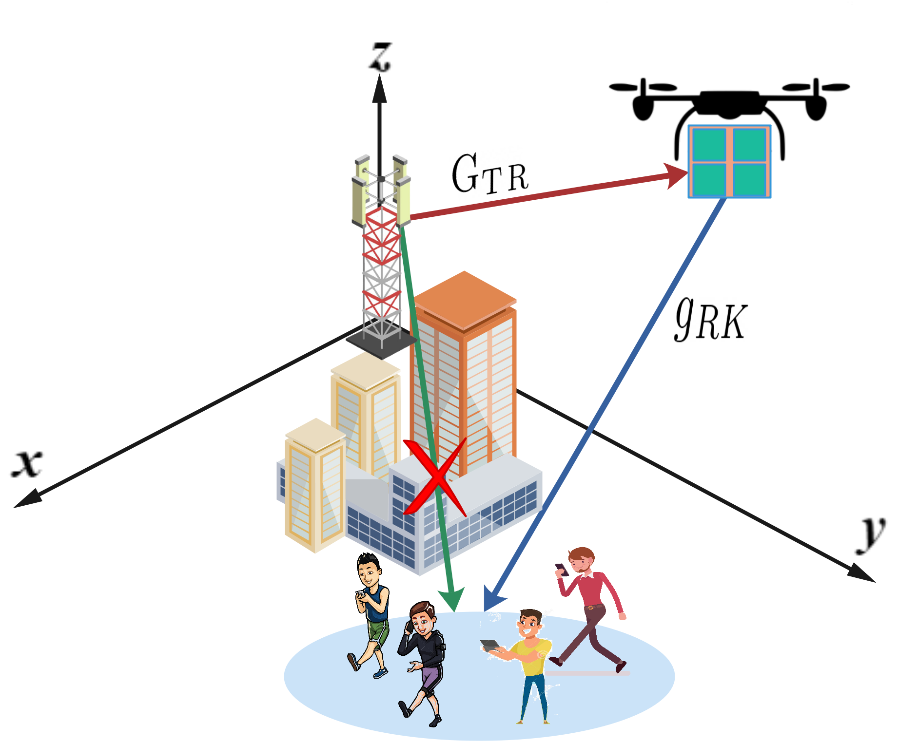
The multiple input-multiple output (MIMO) channel between the antennas of the GBS and the reflecting elements at the ARIS is denoted as and the MISO channel between the ARIS and the GT is defined as . We assume that the channel state information (CSI) is perfectly known at the GBS and reported back to the ARIS over a dedicated control channel.
The ARIS forms a uniform linear array (ULA) of reflecting elements, as in [12]. The phase shift array is denoted as , where is the phase of the reflecting element.
The signal-to-interference plus noise ratio (SINR) at the GT can be written as
| (1) |
where the first term in the denominator is the multi-user interference and the second term the noise variance at the GT. Vector is the beamforming vector of the GT applied at the GBS. The GBS beamforming matrix contains beamforming vectors, . The allocated transmit power for the GT is . The achieved sum-rate of the system can then be calculated as
| (2) |
II-B Channel Model
We consider small-scale Rician fading where a line of sight (LoS) component coexist with non-LoS (NLoS) components for modeling the air-to-ground communications channel between the ARIS and the GBS as well as between the ARIS and the GTs [14].
Equation
| (3) |
models the the MIMO communications channel between the antennas of the GBS and the passive reflecting elements of the ARIS, where is the path loss at the reference distance of , is the 3D distance between the GBS and the ARIS, is the path loss exponent, is the Rician factor, and and are the LoS and NLoS components. Without loss of generality, the entries of are independent and identically distributed (i.i.d.) and are modeled as zero mean and unit variance circularly symmetric complex Gaussian (CSCG) variables, .
The LoS channel component can be expressed as
| (4) |
where and correspond to the channel contributions resulting from the angel of departure (AoD) at the GBS and the angel of arrival (AoA) at the ARIS.
The AoD channel contribution is
| (5) |
where is the carrier wavelength, is the antenna separation, and is the AoD component of the transmitted signal from the GBS to the ARIS. The AoD component can be written as , with being the elevation AoD and the azimuth AoD from the ULA of the GBS.
The AoA can be calculated as
| (6) |
where is the AoA component of the transmitted signal from the GBS to the ARIS. This AoA component is given by , where is the azimuth AoA and is the elevation AoA.
The channel between the ARIS and the GTs,
| (7) |
is a function of the distance based path loss and the LoS and NLoS channel gains. The entries follow the same CSCG distribution that we defined earlier for the . Since the ARIS communicates with the single-antenna GTs over a MISO communications link, the can be defined as
| (8) |
where is the the AoD component of the signal departing from the ARIS, with being the azimuth AoD and the elevation AoD.
II-C Problem formulation
Our objective is to maximize the achievable downlink sum-rate of the MU-MISO communications system by jointly optimizing the active beamforming at the GBS and the passive beamforming at the ARIS. The optimization problem is subject to the GBS power constraint and the ARIS phase shift constraint. The power allocation for each transmission must be less than the maximum allowed transmission power . The transmission power constraint can be formulated as
| (9) |
The ARIS phase shifts are constrained by the unit modulus constraint, that applies to all reflecting elements, where . This establishes the ARIS as a steerable, non-amplifying reflector.
The optimization problem can then be formulated as
| (10) | ||||
III Proposed Solution
Since there is no standard method for solving such a non-convex optimization problem, we investigate data-driven solutions instead of applying conventional mathematical optimization tools. Most of the traditional solutions to equivalent multi-parameter optimization problems are iterative, alternately optimize the parameters, and reach suboptimal results [15].
We propose jointly determining the GBS beamforming matrix and the ARIS phase shifts by applying a transition process based on the current state of the system. Since the next system state is independent of the previous states and actions, the process can be modeled as a Markov decision process (MDP). This facilitates applying a RL algorithm without requiring the knowledge of the system model to find the optimal and .
In what follows, we first describe the deep RL (DRL) model and define the states, the actions, and the reward. Then, we introduce the proposed DDPG algorithm for the DRL model to maximize the sum-rate of the system. The DDPG employs two DNNs—the actor network and the critic network—to avoid intractably high dimensionality for the high state-action space.
III-A Deep Reinforcement Learning Model
The MDP for the RL agent is composed of the state space , the action space , the reward space , and the transition probability space , i.e., . At time slot , the agent observes the state , and based on its policy, takes an action . Depending on the distribution of the transition probability , the agent transfers the system to the new state . Since the transition probability is highly dependent on the environment and it is difficult to obtain, we employ RL, where the agent reaches an optimal action by observing the instant reward and the state transitions while interacting with the environment through the agent’s actions. This means that we do not need to know , but rather need to carefully define the states, the actions, and the reward.
State: The set of states contains the different observations representing the environment and can be defined as . Each state at time slot captures the transmission power of the GBS, the received power of GTs, the previous action, and the GBS-ARIS and the ARIS-GTs channel matrices.
Action: The choices that an agent has to transition from the current state to the next state comprise the action space. We define a set of actions that the agent takes as . Action at time encapsulates two parts: the active beamforming matrix of the GBS and the passive beamforming matrix of the ARIS.
Reward: After taking an action in state at time , the agent receives a reward . This reward is an evaluation metric of the taken action. The agent is rewarded positively for actions that may lead to a desired goal such as the increase of system performance, whereas the agent is penalized if the taken actions are counterproductive. For our system, we define the reward function as the instantaneous sum-rate of the MU-MISO downlink, i.e., .
The objective is to find the optimal policy that maximizes the cumulative discounted reward, where policy is a function that specifies what action to take in each state. The cumulative discounted reward can be written as , where is the discount factor in the time slot that affects the importance of the future reward. The optimal policy can thus be calculated as
| (11) |
Q-learning is a model-free algorithm that is commonly applied to find the optimal policy for the state-action relationship. The Q-value function is used to examine the quality of a state-action pair as a function of the expected cumulative reward under policy . It allows evaluating the transition between states and the actions taken by the agent. It Q values are stored in the Q-table consisting of the environmental states in the rows and the possible actions of the agent in the columns. The table is initially filled with random numbers. The Bellman equation is then used to obtain the optimal state-action pairs [16]. The Q-function that fulfills the Bellman equation can be written as
| (12) |
where the and symbolize the next state and action. The Bellman equation is used through a recursive process to update the Q-values until reaching the optimal Q-value function. The update of the Q-function is formulated as
| (13) | ||||
| (14) |
where is the learning rate that is employed to determine how quickly an agent abandons the previous Q-value for the new Q-value.
Because of scalability limitations and computational infeasibility of calculating every state-action pair in high dimensional state and action spaces of most real-life problems, Q-learning may not be the optimal choice for converging to the optimal . Therefore, and alternative to the time-consuming and impractical use of Q-learning, it is possible to estimate using a function approximator.
Deep neural networks (DNN) can be used as approximators for determining the state-action pairs and policy. It is still possible to converge to a local optimal solution when applying a DNN because of the non-stationary targets and the correlation between the input samples in the time domain. For tackling this problem and breaking the possible correlations between sequential states of the environment, the experience replay is implemented to introduce randomness. When an action is taken by the agent, the system generates a record of experience. At time step , the experience consists of the current state , the action , the reward , and the next state , forming the tuple . Each such experience is buffered in a replay memory with the capacity of , such that . The update of the DRL can now be performed by feeding the mini-batch samples from the replay memory instead of from the last state.
The Q-values of the DRL algorithm are , where corresponds to the weights and the biases of the neural networks that are implemented as part of the DRL algorithm. To reach the best estimate for the Q-values, the DRL needs to find the optimal weights and biases for minimizing the loss function, which is done using the stochastic gradient descent approach. The update of is thus calculated as
| (15) |
where is the learning rate of the stochastic gradient descent updates and is the gradient of the loss function with respect to . Parameter is the loss function that is calculated as the difference between the estimated output of the neural network and the actual output, that is,
| (16) |
where is the target Q-value with target coefficients and is the actual Q-value. To produce both actual and target Q-values, the DRL implements two identical neural networks known as the training neural network and the target neural network. The training network outputs the Q-values associated with the actions of the agent in each state. The target network supervises the training network by providing the target Q-values obtained from the Bellman equation.
III-B Deep Deterministic Policy Gradient
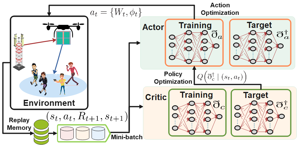
DRL can be effective when applied to discrete action outputs, but not for continuous action spaces. We therefore propose to employ the DDPG [13] for continuous decision‐making by efficiently learning and acting in the continuous action spaces of the active and passive beamforming systems of Fig. 1.
The DDPG relies on two types of DNNs—the actor and the critic networks, each with its training and target network (Fig. 2)—to avoid the intractably high dimensionality of the state-action space. It develops the mapping function between the input environment states and the agent actions to establish a deterministic policy that maximizes the long-term reward. The actor network is adopted to generate the deterministic policy that maximizes the output of the critic network; that is, it takes the states as the input and outputs the deterministic actions to the agent. The critic network is designed to simulate the Q-value function and evaluate the deterministic policy generated by the actor network; that is, it takes the deterministic policy of the actor network as its input and outputs the Q-value for these actions.
The updates of the training critic network are obtained as
| (17) |
where captures the weights and the bias of the training critic network, is the learning rate, and is the gradient. Parameter is the loss function of the training critic network and can be calculated as
| (18) |
where is the action of the agent that follows the deterministic policy drafted by the target actor network and captures the network’s weights and bias.
It is worth mentioning that the update of the training network occurs more frequently than the update of the target network. The training actor network update is defined as
| (19) |
where corresponds to the weights and bias of the training actor network , is the learning rate, is the gradient of the target critic network output with reference to the taken action, and is the gradient of the training actor network with respect to . The gradient is introduced in the update of the training actor network to guarantee that the upcoming selection of the action by the critic network is the preferred one for maximizing the Q-value function.
Coupled with the updates of the training critic and training actor networks, the target critic and target actor network updates are defined as
| (20) | |||
| (21) |
where and are the learning rates for updating the critic and actor networks, respectively. The details of the proposed DDPG solution are presented in Algorithm 1. The DDPG can be integrated into radio access network intelligent controllers (RICs) where the training can be done at the non-real time-RIC and the inference at the near-real time RIC of future O-RAN systems [17].
IV Numerical Analysis and Discussion
![[Uncaptioned image]](/html/2207.06064/assets/x2.png)
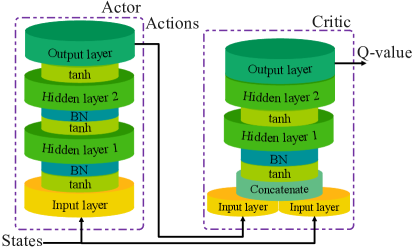
We numerically analyze the performance of the proposed scheme for optimizing the downlink sum-rate of the ARIS assisted MU-MISO system. The GTs are randomly distributed in a 2D circular area that is centered at . Table I provides the parameters for the simulated scenarios and the hyperparameters for the proposed DDPG algorithm. The critic and actor DNNs employ the same structure and consist of layers: the input layer with neurons, two fully connected hidden layers with neurons each, and the output layer with neurons. Parameter corresponds to the size of the state space and corresponds to the size of the action space. All DNNs employ as the activation function in all layers and with adaptive learning as the optimizer, where and with the decaying rates an for the critic and actor networks, respectively. Fig. 3 illustrates the structure of the critic and actor DNN designs for the proposed DDPG.
For the performance evaluation, we compare the resulting reward of the DDPG-based algorithm for optimizing the joint transmit beamforming and phase shifts of ARIS (DDPG-based A&P for active and passive beamforming optimization) against a deep Q-learning (DQL)-based approach (DQL-based A&P) which uses the same objective function and the same reward function as the proposed DDPG algorithm. We also compare our solution to a baseline technique (DDPG-based A) that only optimizes the GBS beamforming matrix and chooses the ARIS phase shifts randomly. The DQL-based solution uses the same DNN structure used for the critic and the actor networks.
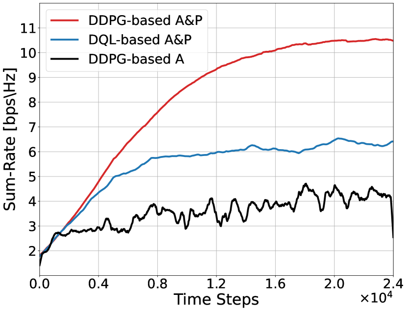
Figure 4.a illustrates the achieved sum-rates of the MU-MISO downlinks over time in discrete time slots for the three optimization methods. The sum-rate corresponds to the reward function. Overall we notice a significant increase in the sum-rate of the proposed DDPG-based algorithm over the DQL-based algorithm and the baseline. The superiority of the DDPG over the baseline applying random phases can be attributed to the RIS being able to influence the propagation environment in such a way to suppress the multi-user interference. The superiority of the DDPG over the DQL solution comes from the actor-critic relationship—described in the previous section—that is employed for optimizing the policy that reflects on the agent’s action choices. The DQL’s sum-rate fluctuates steadily around for most of the training time. The achieved sum-rate of the DDPG converges to roughly 1.75x the sum-rate of the DQL. This indicates the quality of the actions generated by the DDPG, whereas the DQL converges to a local minimum.
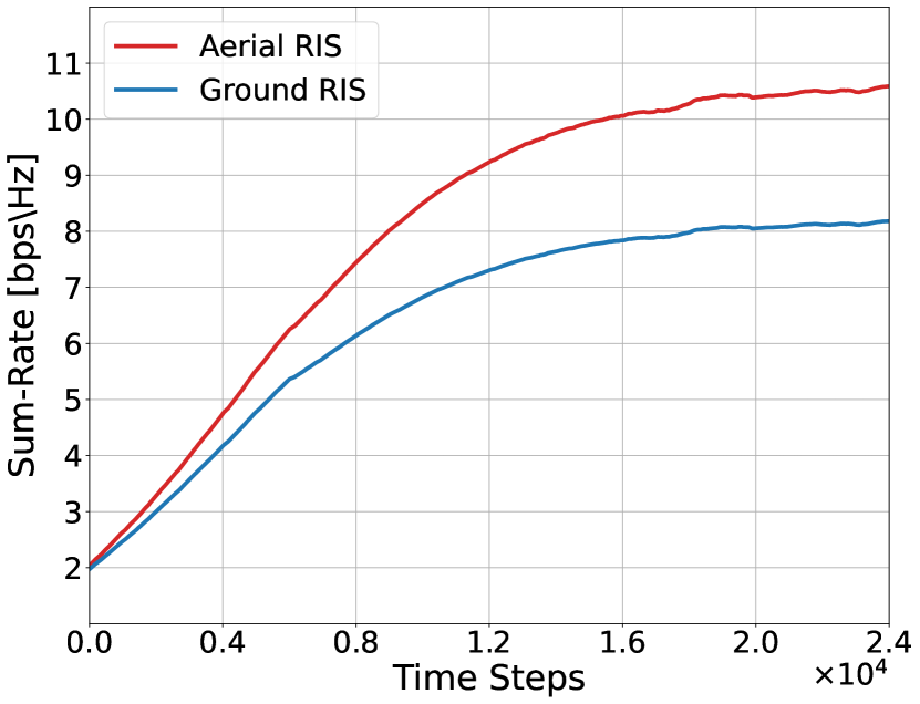
To provide more insights into the performance of the proposed ARIS-assisted MU-MISO downlink system, Fig 4.b presents a comparison of the achieved sum-rate of utilizing the ARIS versus a ground RIS, where the RIS is deployed on a ground building. The ARIS scheme outperforms the ground RIS, achieving a 30% higher sum-rate. This can be attributed to the stronger LoS links that are achievable by the ARIS and that empower the A2G communication channels over the equivalent ground channels.
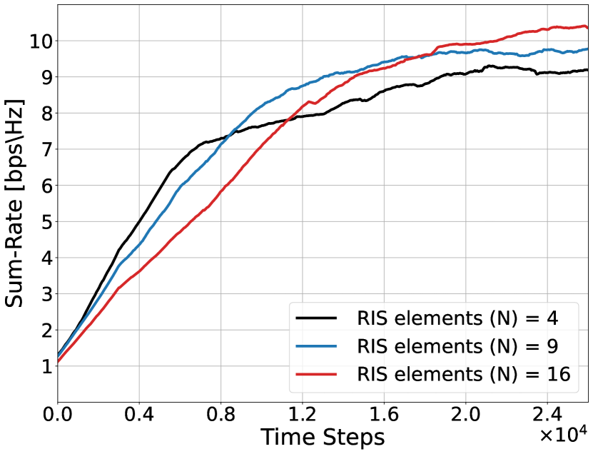
Figure 4.c shows the sum-rate of the DDPG algorithm as a function of the number of reflecting elements. As expected, an ARIS with more elements converges to a higher sum-rate, but it takes longer to converge because of the nature of the problem that has a larger number of states and actions. The sum-rate improves by when employing an ARIS with 16 over 4 reflecting elements, by for 9 over 4 elements, and by for 16 over 9 elements.
V Conclusions
This paper has presented a driven-based solution to jointly optimize the active beamforming at the GBS and the passive beamforming at the ARIS for increasing the downlink sum-rate of a MU-MISO system. We have provided the detailed design options and parameters of the proposed DDPG algorithm. We have numerically analyzed the performance of the proposed solution and compared it with the DQL and a baseline technique. The results have shown that the DDPG outperforms other techniques and effectively increases the sum-rate. Motivated by these results, we propose studying multiple DDPG agents and analyzing the performance of the ARIS-enhanced communications system by optimizing both the beamforming and the location/trajectory of the ARIS.
Acknowledgment
This work was supported in part by NSF award CNS-2120442.
References
- [1] A. S. Abdalla, K. Powell, V. Marojevic, and G. Geraci, “UAV-assisted attack prevention, detection, and recovery of 5G networks,” IEEE Wireless Commun., vol. 27, no. 4, pp. 40–47, 2020.
- [2] R. Amer, W. Saad, and N. Marchetti, “Mobility in the sky: Performance and mobility analysis for cellular-connected UAVs,” IEEE Trans. Commun., vol. 68, no. 5, pp. 3229–3246, 2020.
- [3] B. Shang, et al, “Spectrum sharing for UAV communications: Spatial spectrum sensing and open issues,” IEEE Veh. Technol. Mag., vol. 15, no. 2, pp. 104–112, 2020.
- [4] A. S. Abdalla and V. Marojevic, “Communications standards for unmanned aircraft systems: The 3GPP perspective and research drivers,” IEEE Commun. Standards Mag., vol. 5, no. 1, pp. 70–77, 2021.
- [5] V. Marojevic, et al., “Advanced wireless for unmanned aerial systems: 5G standardization, research challenges, and aerpaw architecture,” IEEE Veh. Technol. Mag., vol. 15, no. 2, pp. 22–30, 2020.
- [6] A. S. Abdalla, T. F. Rahman, and V. Marojevic, “UAVs with reconfigurable intelligent surfaces: Applications, challenges, and opportunities,” arXiv 2012.04775, pp. 1–7, 2020.
- [7] T. Shafique, H. Tabassum, and E. Hossain, “Optimization of wireless relaying with flexible UAV-borne reflecting surfaces,” IEEE Trans. Commun., vol. 69, no. 1, pp. 309–325, 2021.
- [8] J. Fang, et al., “Secure intelligent reflecting surface assisted UAV communication networks,” in IEEE ICC Workshops, 2021, pp. 1–6.
- [9] H. Lu et al., “Aerial intelligent reflecting surface: Joint placement and passive beamforming design with 3D beam flattening,” IEEE Trans. Wireless Commun., vol. 20, no. 7, pp. 4128–4143, 2021.
- [10] C. Huang, R. Mo, and C. Yuen, “Reconfigurable intelligent surface assisted multiuser MISO systems exploiting deep reinforcement learning,” IEEE J. Sel. Areas Commun., vol. 38, no. 8, pp. 1839–1850, 2020.
- [11] Q.-U.-A. Nadeem, et al., “Asymptotic max-min SINR analysis of reconfigurable intelligent surface assisted MISO systems,” IEEE Trans. Wireless Commun., vol. 19, no. 12, pp. 7748–7764, 2020.
- [12] Q. Wu and R. Zhang, “Intelligent Reflecting Surface Enhanced Wireless Network via Joint Active and Passive Beamforming,” IEEE Trans. Wireless Commun., vol. 18, no. 11, pp. 5394–5409, 2019.
- [13] D. Silver, et al., “Deterministic policy gradient algorithms,” in 31st International Conference on Machine Learning, Bejing, China, 22–24 Jun. 2014, pp. 387–395.
- [14] Z. Mohamed and S. Aïssa, “Leveraging UAVs with Intelligent Reflecting Surfaces for Energy-Efficient Communications with Cell-Edge Users,” in 2020 IEEE ICC Workshops, 2020, pp. 1–6.
- [15] A. S. Abdalla and V. Marojevic, “Securing mobile multiuser transmissions with UAVs in the presence of multiple eavesdroppers,” IEEE Trans. Veh. Technol., vol. 70, no. 10, pp. 11 011–11 016, 2021.
- [16] K. Arulkumaran et al., “Deep reinforcement learning: A brief survey,” IEEE Signal Processing Magazine, vol. 34, no. 6, pp. 26–38, 2017.
- [17] A. S. Abdalla, P. S. Upadhyaya, V. K. Shah, and V. Marojevic, “Toward next generation open radio access network–what O-RAN can and cannot do!” arXiv preprint arXiv:2111.13754, 2021.