captionUnknown document class \WarningFilterlatexA float is stuck
Light-induced hexatic state in a layered quantum material
Abstract
The tunability of materials properties by light promises a wealth of future applications in energy conversion and information technology. Strongly correlated materials such as transition-metal dichalcogenides (TMDCs) offer optical control of electronic phases, charge ordering and interlayer correlations by photodoping. Here, we find the emergence of a transient hexatic state in a TMDC thin-film during the laser-induced transformation between two charge-density wave (CDW) phases. Introducing tilt-series ultrafast nanobeam electron diffraction, we reconstruct CDW rocking curves at high momentum resolution. An intermittent suppression of three-dimensional structural correlations promotes a loss of in-plane translational order characteristic of a hexatic intermediate. Our results demonstrate the merit of tomographic ultrafast structural probing in tracing coupled order parameters, heralding universal nanoscale access to laser-induced dimensionality control in functional heterostructures and devices.
C ollective behaviour beyond the single-particle picture fosters a variety of fundamental physical phenomena, such as superconductivity 1 and ferromagnetism 2, which involve the establishment of long-range order below a critical temperature. Due to weaker screening and reduced phase space volumes for scattering, collective excitations are particularly important in low-dimensional systems. Prominently, plasmon and spin waves constitute elementary excitations of the one-dimensional Luttinger liquid 3.
For ideal systems of reduced dimensionality 4, the Mermin-Wagner-Hohenberg theorem prohibits long-range ordering at finite temperatures, owing to thermal fluctuations 5. Strictly speaking, this precludes symmetry-breaking phase transitions. Instead, the transition from a quasi-long-range ordered two-dimensional solid to a liquid phase is described within the framework of Kosterlitz-Thouless-Halperin-Nelson-Young (KTHNY) theory 6, 7. While the solid-liquid transition is always of first order in three-dimensional systems 8, the theory predicts two successive second-order transitions in two dimensions via a hexatic phase. This intermediate is characterised by intact orientational but reduced translational order arising from the presence of unbound topological defects 7, 9.
Experimental realisations of this transition have been actively pursued with two-dimensional model systems of colloidal spheres 9, particles physisorbed on crystalline substrates 8, skyrmion lattices 10 and technologically relevant smectic liquid crystals 11. Yet, quasi-two-dimensional character is also readily found in layered materials 4. Among those, transition metal dichalcogenides (TMDCs) stand out due to their highly anisotropic correlations 12. This leads to the occurrence of direct-to-indirect band gap transitions 13, layer- and doping-dependent superconductivity 14, 15, 16, 17, and the formation of charge-density waves (CDWs) 18. Due to the delicate interplay between the various degrees of freedom, the properties of these systems, often referred to as quantum materials 19, are highly tunable by external stimuli 20, 21, 22, 23, 24, 25.
As a consequence, TMDCs susceptible to charge ordering often exhibit more than one thermodynamic CDW phase, governed by a varying balance of, e.g., electron-phonon coupling, electronic correlations and Fermi surface nesting 18. These phases may exhibit drastically different macroscopic properties, but only subtle changes of the periodic lattice distortion (PLD) coupled to the CDW 26, 27, 28. As demonstrated in a wide range of ultrafast experiments, optical pulses can be used to transiently suppress CDW phases and drive transitions between them 29, 26, 27, 30, 31, 32, 33, 34, 35, 36, 37, 38, 39, 40, 41, 42, 43, 44, induce transient CDW order 45 or open up paths into thermodynamically inaccessible hidden states 46, 30, 47, 48. The high degree of in-plane structural disorder induced by the optical excitation not only influences switching behaviour 40, 49, 43, but also the final phase texture 46, 42, 47.
The effective dimensionality of a CDW system is determined by the coupling between neighbouring layers. Hence, a phase transition that modifies interlayer correlations may lead to the occurrence of a dimensional crossover 50, 51. On ultrafast timescales, CDW stacking dynamics have recently been studied by means of ultrafast electron 39, 44 and x-ray diffraction 52, 43. In particular, an optically induced breakdown of excitonic correlations was shown to quench out-of-plane order 44, and careful tuning of the photoexcitation density was used to realise interlayer phase boundaries with two-dimensional characteristics 53 – raising the question if optical control may serve as a gateway to fundamentally low-dimensional phenomena such as the KTHNY transition.
In this article, we report on the observation of transient hexatic order in a nascent incommensurate CDW phase. We use ultrafast high-coherence nanobeam diffraction to track the three-dimensional phase ordering after femtosecond optical excitation. At early times and prior to the establishment of the equilibrium stacking sequence, we identify a quasi-two-dimensional state characterised by a pronounced anisotropic broadening of diffraction spots. We reproduce the experimentally observed behaviour in time-dependent Ginzburg-Landau simulations and attribute it to the presence of unbound topological defects, consistent with the predictions of KTHNY theory.
Experimental approach and results
Ultrafast high-coherence nanobeam diffraction
Over the past two decades, ultrafast electron diffraction (UED) 54, 55 has evolved into a highly sensitive technique to probe structural phase transitions 37, 38, 39, 40, 41, 56, 42, 23, 45, 36, 43, 44 and transient phonon populations 33, 57, 58 on femtosecond time scales. State-of-the-art time-resolved electron diffraction instrumentation typically uses large-diameter beams ( spot size) for averaged probing of CDW amplitudes, addressing a compromise between a small spot size and sufficient reciprocal-space resolution. Ultrafast Transmission Electron Microscopes (UTEMs) 59, 60, 61, 62, 31, 63 are versatile devices for ultrafast electron diffraction 64, 65. In particular, laser-triggered field emitters yield UTEM beams of enhanced transverse coherence 61, 62, 63.
As the key experimental innovation of the present study, we harness these capabilities to conduct femtosecond electron diffraction combining high reciprocal-space resolution with a particularly narrow electron beam, in extended series of eight beam tilts. A concomitant transverse coherence length of up to enables a precise measurement of in-plane spot profiles and allows to distinguish phases characterised by similar periodicities. Simultaneously, the nanometric probe beam guarantees diffraction from a sample region of sufficient homogeneity in terms of thickness and orientation, as required for the quantitative investigation of stacking dynamics. The fingerprint of such structural modifications is often encoded in low-intensity diffracted signals. We increase the sensitivity to these features by means of a sample design tailored to drive the transformation at an unprecedented laser repetition rate of , maximising the duty cycle of our measurement scheme.
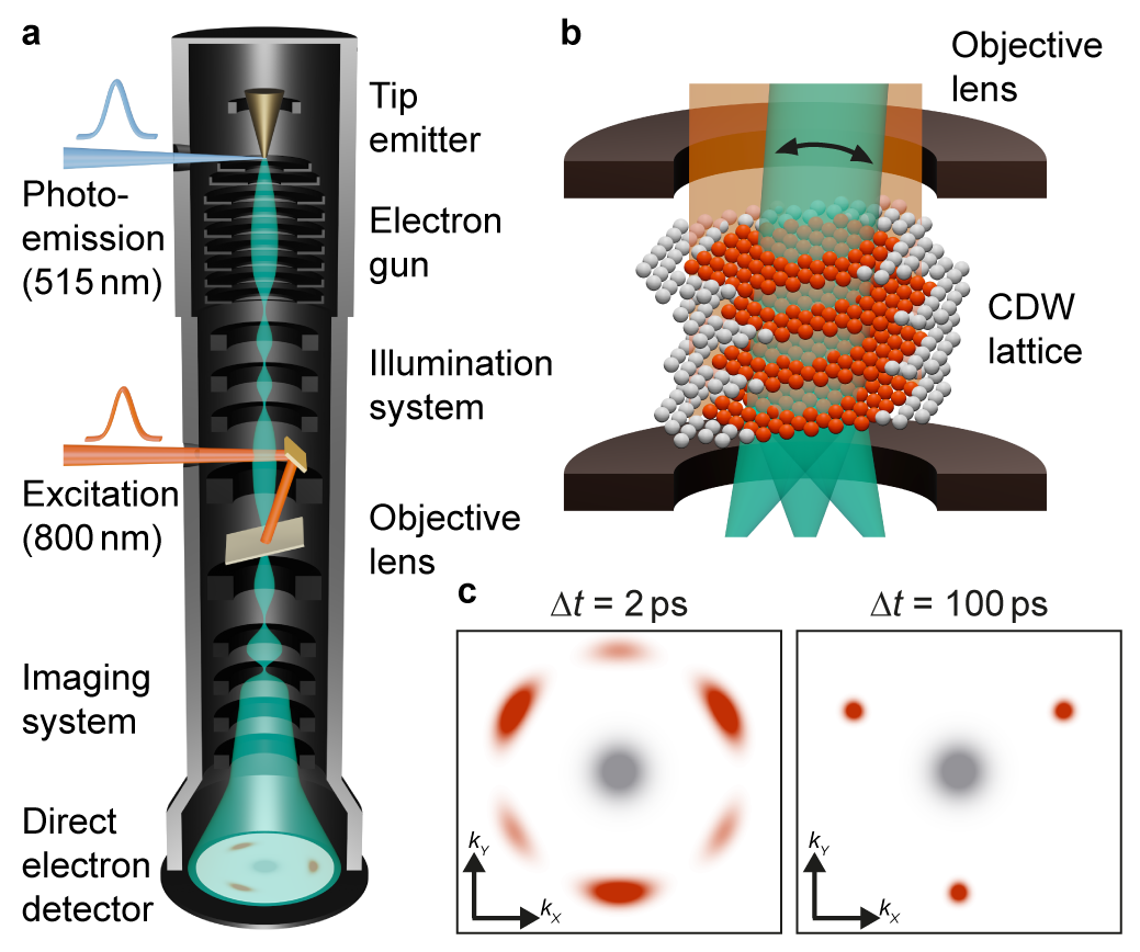
In the experiments (Fig. 1), we excite a free-standing thin film of the prototypical CDW material 1T-TaS2 at room temperature, using ultrashort laser pulses ( wavelength, duration, between and fluence). As a function of a variable temporal delay , we capture the transient distribution of CDW spot intensities and profiles using high-coherence ultrashort electron pulses ( beam energy, duration, between and spot size, below convergence semi-angle, see Supplementary Information and Fig. S3 for fluence-dependent delay scans).
Incommensurate CDW phases in 1T-TaS2
We investigate the photoinduced transition between two incommensurate CDW superstructures in 1T-TaS2 (grey and red regions in Fig. 1b). In thermal equilibrium and at temperatures above , the in-plane modulation wave vectors (with ) of the CDW/PLD are aligned along the lattice vectors of the hexagonal host 66. Due to the presence of a gap-less long-range phase fluctuation (or phason) mode, the CDW in this high-temperature incommensurate phase (in short IC phase) is effectively free-floating and only weakly coupled to neighbouring layers 67. As such, the IC phase in 1T-TaS2 is an ideal host for topological defects and, potentially, hexatic ordering 68.
Below the phase transition temperature, the modulation remains incommensurate and the wave vectors form an angle of with the lattice vectors (nearly commensurate or NC phase). With significant contributions from higher harmonics, the real-space structure exhibits a network of discommensurations separated by domains of commensurate character in which the CDW/PLD is locally locked-in with the crystal structure 66, 69. Despite their different in-plane structures, both phases exhibit a commensurate, three-fold stacking periodicity along the out-of-plane direction (, see Fig. 1b) 66, 69.
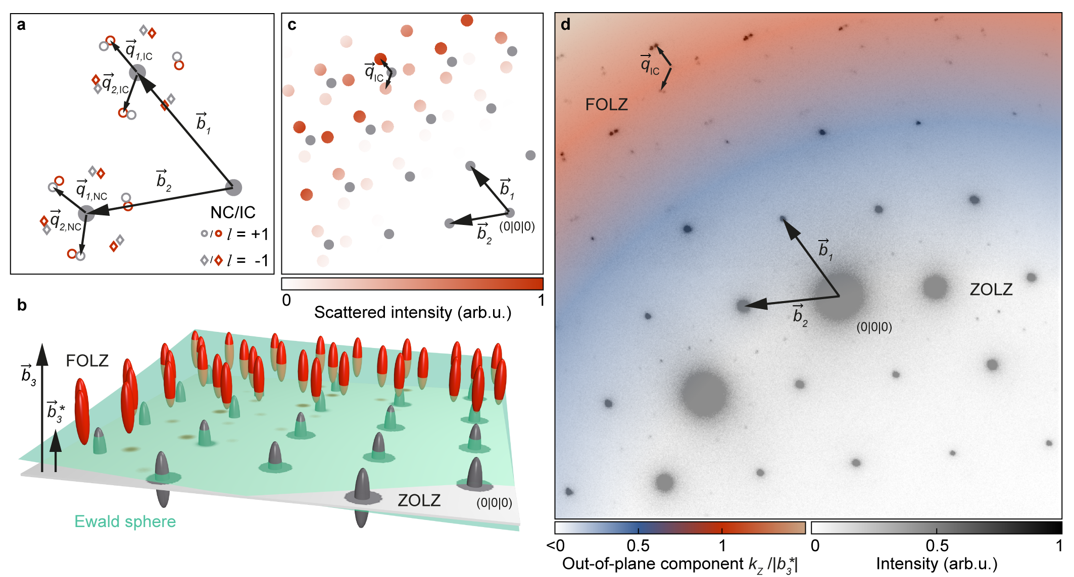
The reciprocal lattice of the host material is given by basis vectors . The modulation wave vectors span the reciprocal CDW lattice around every individual main lattice point (Fig. 2a). Hence, each lattice point can be identified by69
| (1) |
This notation absorbs the commensurate out-of-plane component of the CDW in a supercell, effectively leading to a shorter reciprocal lattice vector and certain systematic absences in diffraction experiments. Specifically, whereas all main reflections (with ) lie in planes , first-order CDW spots with , and (and those with opposite sign) are located in planes with non-vanishing -components. Thus, they only appear upon tilting the electron beam away from the zone axis 69, 39.
A visualisation of the corresponding diffraction geometry is shown in Fig. 2b. Under tilted-beam conditions, electron diffractograms typically feature spots in more than one Laue zone (Fig. 2d). Main reflections are located in the zero-order Laue zone (ZOLZ) close to the unscattered beam and appear bright compared to the second-order CDW spots surrounding them. As a result of the CDW stacking sequence, first-order CDW reflections are found in the first-order Laue zone (FOLZ) and at larger wave vectors for moderate beam tilts (see also Supplementary Movies S1 and S2).
Dynamics of the in-plane correlation length
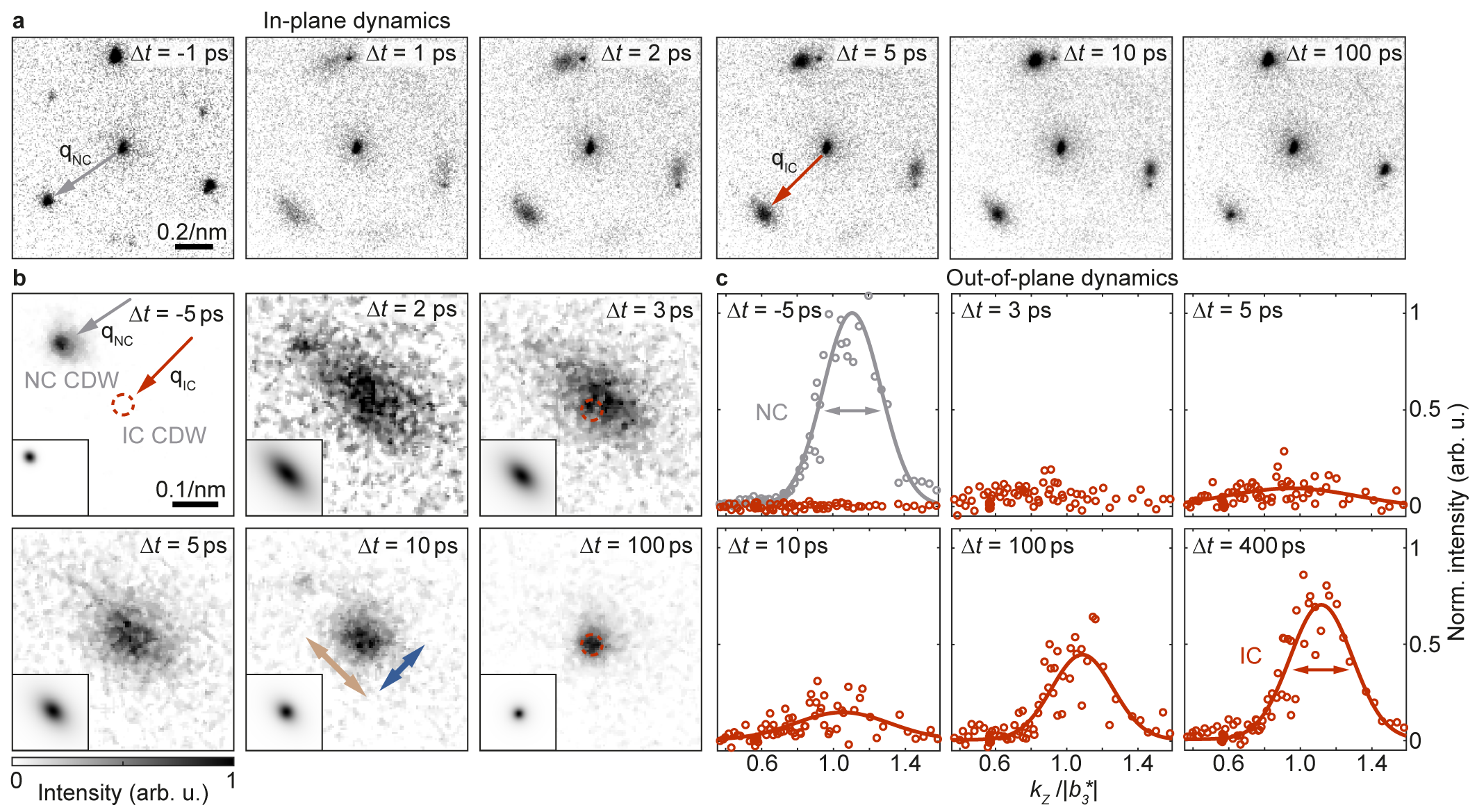
Figure 3a shows a series of time-resolved diffraction patterns, averaged over several main reflections in the FOLZ. Before optical excitation (time-zero), we observe a triplet of sharp first-order spots of the initial NC phase. The additional low-intensity reflections in-between stem from higher CDW orders (). After excitation, the NC spot intensity is largely suppressed within . Simultaneously, nearby reflections with , and emerge, which evidence the nascent IC phase and exhibit a significant anisotropic broadening 41, 40, 70, as well as a few-picosecond increase in intensity 38 (cf. also ref. 39). Additionally, a slight increase of scattered intensity is detected at , and , i.e., opposite of the bright IC spots. Only after these early-stage dynamics, the spot shapes become isotropic, and solely the bright IC spots remain (see image at ).
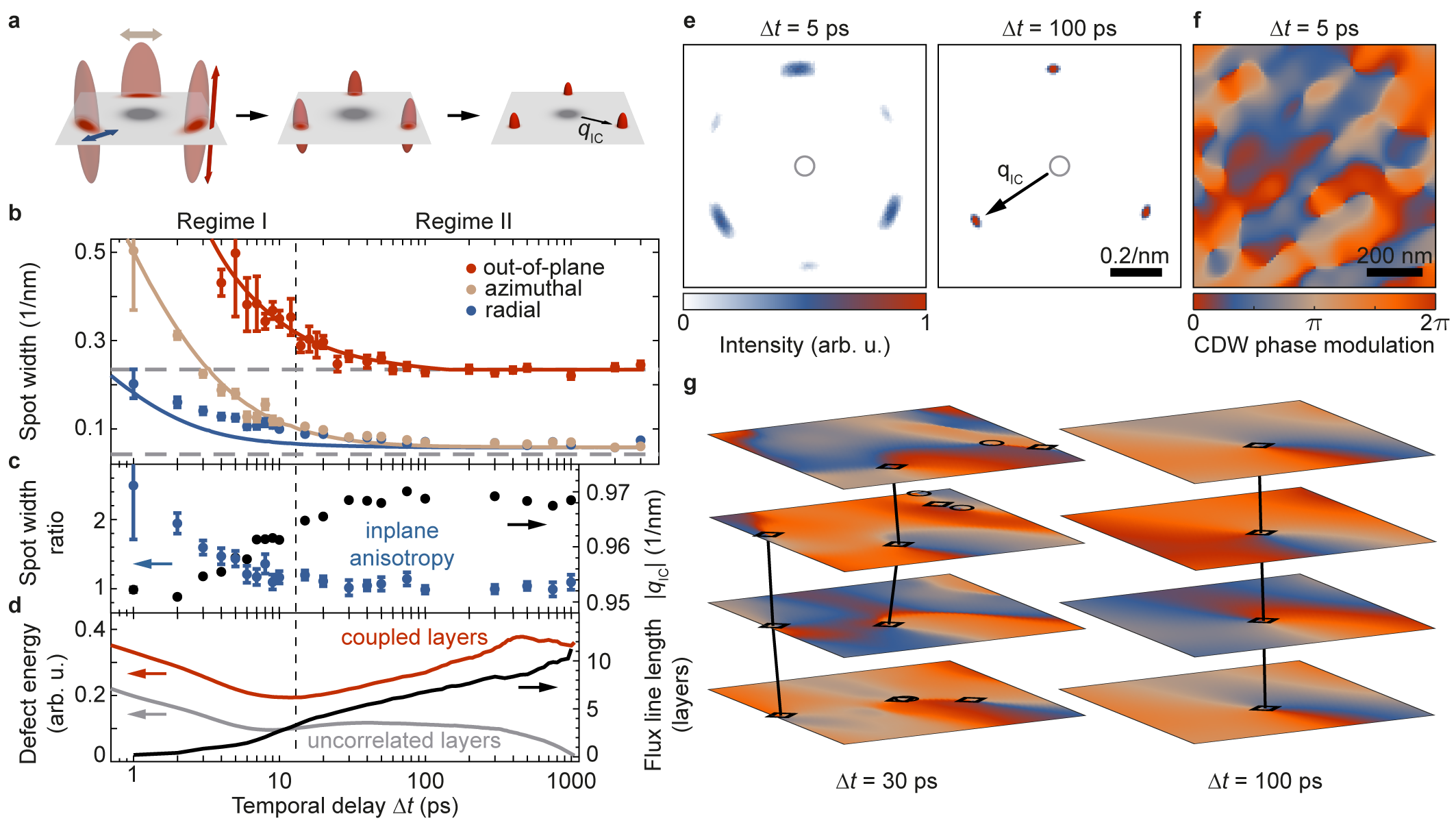
The different spot profiles along azimuthal and radial directions (in relation to the nearby main reflection) is a most characteristic hallmark for the presence of a hexatic phase 7. For a quantitative analysis, we recorded a second image series with a longer camera length, i.e., optimised reciprocal-space resolution (Fig. 3b). We fit the spot shape at every temporal delay (see insets) and extract the azimuthal and radial spot widths (indicated by brown and blue arrows, respectively). The results are shown in Fig. 4b (brown and blue data points). From a spot width ratio shortly after optical excitation (blue circles in Fig. 4c), the reflections assume an isotropic, yet broadened shape within (temporal regime I). On longer timescales, the IC spot width finally approaches that of the NC peak measured before time-zero (temporal regime II; dashed grey line in Fig. 4b). Notably, this behaviour coincides with a monotonous growth of the IC wave vector, which initially is shorter than in the equilibrium phase at late delay times (black circles in Fig. 4c).
Reconstruction of the CDW rocking curve
The observed evolution of the in-plane spot profile suggests the presence of hexatic order during temporal regime I. In order to test this hypothesis, we probe the effective dimensionality of the system as induced by the optical excitation, analysing intensities of reflections with different out-of-plane momenta.
Under tilted-beam conditions, the lattice rod is densely sampled across the various spots present in the FOLZ of every single diffractogram (see visualisation in Fig. 2b and colour overlay in Fig. 2d for the experimental tilt angle of ). To further enhance sensitivity and fully cover reciprocal space, we perform delay scans with eight different beam tilts. Correlating the scattered intensities before time-zero with dynamical diffraction simulations, we determine the tilt angle for any of these scans with an accuracy better than (see Supplementary Information and Fig. S1 for a more detailed description).
Sorting scattered intensities of spots with comparable CDW structure factors (Fig. 2c) by their associated out-of-plane components , we reconstruct the CDW rocking curve from individual IC reflections with a total of values of throughout our tilt series at every stage of the dynamics (Fig. 3c and Supplementary Information). At early times, the intensity increases independently of , indicating a pronounced elongation of the reciprocal lattice rods along the direction (see Fig. 3c at and Supplementary Fig. S2). Subsequently, a well-defined spot profile emerges and narrows until approaching that of the NC phase measured before time-zero (red data points and dashed grey line in Fig. 4b).
Discussion
The two CDW modifications involved in the experiment are not commensurate with each other. As a result, there is no continuous global deformation of the crystal during the phase transition. Instead, photoexcitation gives rise to a high density of topological defects, causing the broadening of diffraction spots directly after time-zero. In the past, both CDW dislocations 40, 42, 70, 43 and domain walls 41, 43 have been invoked to describe the transiently disordered structure on a microscopic scale. While CDW states in 1T-TaS2 are known to support both types of topological features 47, the kinetics and interplay between defects in- and out-of-plane remain largely uncertain.
We interpret the evolution of the reconstructed diffraction spots in terms of a transient hexatic phase supported by a temporary suppression of interlayer correlations. Specifically, the observed anisotropic in-plane broadening of CDW reflections (Fig. 4d) indicates a pronounced loss of translational order. This feature is characteristic of KTHNY behaviour, relating the condensation of a two-dimensional crystalline phase via a hexatic intermediate to the pair-wise annihilation of point-like defects 7. In our measurements, the occurrence of such a mechanism is further substantiated by the temporal evolution of the IC wave vector (black circles in Fig. 4c) whose initial shortening has recently been attributed to a dislocation-induced self-doping of the electronic system 43. The concurrent, highly uncorrelated out-of-plane structure is apparent from the elongation of reciprocal lattice rods (Fig. 3c and Fig. 4b), giving rise to the simultaneous visibility of all six IC reflections in the same Laue zone (Fig. 3a, to ).
To further explore the notion that a gas of dislocation-type topological defects governs the initial stages of the IC phase formation kinetics, and to understand how three-dimensional ordering affects this process, we implement a multilayer time-dependent Ginzburg-Landau simulation. The underlying free-energy functional is derived from Nakanishi’s model 71 describing the most important CDW phases in 1T-TaS2 and their out-of-plane configurations (see Methods for a more detailed description). We express the IC modulation in terms of three coupled order parameters corresponding to the directions of the three in-plane modulation wave vectors and the layer in the atomic structure. The physical charge-density modulation (see Supplementary Fig. S4) is then given by
| (2) |
This model is capable of closely reproducing the experimentally observed temporal evolution of the reciprocal lattice rod (solid lines in Fig. 4b). For the associated set of parameters, the early-stage dynamics are characterised by a high density of uncorrelated phase singularities (Fig. 4f). In this state, local energy minimisation leads to a spatially anisotropic character of the phases of the individual order parameters (Fig. 4e), causing the typical anisotropic in-plane spot shape shown in Fig. 3b. From here on, a pairing of singularities with opposite chirality in the phases of two of the three order parameters leads to the formation of physical CDW dislocations, and enables a local build-up of the PLD amplitude. The evolution of the average free energy associated with an individual phase vortex parallels that of a purely two-dimensional system, as seen for a reference simulation without interlayer coupling (red and grey curves in Fig. 4d, respectively). We therefore believe that the observed loss of stacking order at early times is a prerequisite for inducing the intrinsically two-dimensional hexatic intermediate in 1T-TaS2. It is intriguing to speculate whether such a state could in fact be realised as a thermodynamically stable phase during the metallic-to-IC transition in a 1T-TaS2 mono-layer.
Beyond temporal delays of and after the spot shape anisotropy has decayed, we observe the onset of three-dimensional behaviour. In contrast to the two-dimensional reference system, the energy of individual vortices increases, and their resulting correlation in adjacent layers leads to the formation of ‘flux lines’ (black lines in Fig. 4d and g, see Methods for a more detailed description). In parallel, the establishment of long-range order is driven by the annihilation of singularities within each of the , eventually reaching correlation lengths at late times that exceed the transverse electron beam coherence length in the experiment.
In conclusion, the identification of hexatic order and stacking dynamics in our study is enabled by ultrafast diffraction with a nanoprobe of exceptional collimation. These results tie in with recent observations of laser-induced transient phases 34 and dimensional cross-overs 44, 53, exemplifying how optical control over interlayer correlations can be used to host low-dimensional states and transitions. Addressing a recurring experimental challenge in ultrafast and materials science, this approach promises to advance high-resolution non-equilibrium investigations in systems characterised by weak structural signatures, sub-micron sample sizes and considerable spatial heterogeneity 72. As such, nanoscale structural analysis will guide the design of applications harvesting laser-induced functionality by material composition and tailored responses to external stimuli.
References
- [1] Orenstein, J. & Millis, A. J. Advances in the Physics of High-Temperature Superconductivity. Science 288, 468–474 (2000).
- [2] Spaldin, N. A. & Fiebig, M. The Renaissance of Magnetoelectric Multiferroics. Science 309, 391–392 (2005).
- [3] Voit, J. One-dimensional Fermi liquids. Reports on Progress in Physics 58, 977–1116 (1995).
- [4] Li, W., Qian, X. & Li, J. Phase transitions in 2D materials. Nature Reviews Materials 6, 829–846 (2021).
- [5] Hohenberg, P. C. Existence of Long-Range Order in One and Two Dimensions. Physical Review 158, 383–386 (1967).
- [6] Kosterlitz, J. M. Kosterlitz–Thouless physics: a review of key issues. Reports on Progress in Physics 79, 026001 (2016).
- [7] Nelson, D. R. & Halperin, B. I. Dislocation-mediated melting in two dimensions. Physical Review B 19, 2457–2484 (1979).
- [8] Birgeneau, R. J. & Horn, P. M. Two-Dimensional Rare Gas Solids. Science 232, 329–336 (1986).
- [9] Gasser, U., Eisenmann, C., Maret, G. & Keim, P. Melting of Crystals in Two Dimensions. ChemPhysChem 11, 963–970 (2010).
- [10] Huang, P. et al. Melting of a skyrmion lattice to a skyrmion liquid via a hexatic phase. Nature Nanotechnology 15, 761–767 (2020).
- [11] Zaluzhnyy, I. A., Kurta, R., Sprung, M., Vartanyants, I. A. & Ostrovskii, B. I. Angular structure factor of the hexatic-B liquid crystals: bridging theory and experiment. Soft Matter 18, 783 (2022).
- [12] Manzeli, S., Ovchinnikov, D., Pasquier, D., Yazyev, O. V. & Kis, A. 2D transition metal dichalcogenides. Nature Reviews Materials 2, 17033 (2017).
- [13] Wang, Q. H., Kalantar-Zadeh, K., Kis, A., Coleman, J. N. & Strano, M. S. Electronics and optoelectronics of two-dimensional transition metal dichalcogenides. Nature Nanotechnology 7, 699–712 (2012).
- [14] Sipos, B. et al. From Mott state to superconductivity in 1T-TaS2. Nature Materials 7, 960–965 (2008).
- [15] Xi, X. et al. Strongly enhanced charge-density-wave order in monolayer NbSe2. Nature Nanotechnology 10, 765 (2015).
- [16] Luo, H. et al. Differences in Chemical Doping Matter: Superconductivity in Ti1– xTaxSe2 but Not in Ti1–xNbxSe2. Chemistry of Materials 28, 1927–1935 (2016).
- [17] Ugeda, M. M. et al. Characterization of collective ground states in single-layer NbSe2. Nature Physics 12, 92–97 (2016).
- [18] Rossnagel, K. On the origin of charge-density waves in select layered transition-metal dichalcogenides. Journal of Physics: Condensed Matter 23, 213001 (2011).
- [19] Tokura, Y., Kawasaki, M. & Nagaosa, N. Emergent functions of quantum materials. Nature Physics 13, 1056–1068 (2017).
- [20] Fausti, D. et al. Light-Induced Superconductivity in a Stripe-Ordered Cuprate. Science 331, 189–191 (2011).
- [21] Poellmann, C. et al. Resonant internal quantum transitions and femtosecond radiative decay of excitons in monolayer WSe2. Nature Materials 14, 889–893 (2015).
- [22] Borzda, T. et al. Charge Photogeneration in Few-Layer MoS2. Advanced Functional Materials 25, 3351–3358 (2015).
- [23] Sie, E. J. et al. An ultrafast symmetry switch in a Weyl semimetal. Nature 565, 61–66 (2019).
- [24] Bao, C., Tang, P., Sun, D. & Zhou, S. Light-induced emergent phenomena in 2D materials and topological materials. Nature Reviews Physics 4, 33–48 (2022).
- [25] Schmitt, D. et al. Formation of moire interlayer excitons in space and time. Preprint at https://arxiv.org/abs/2112.05011 (2021). eprint 2112.05011.
- [26] Hellmann, S. et al. Ultrafast Melting of a Charge-Density Wave in the Mott Insulator 1T-TaS2. Physical Review Letters 105, 187401 (2010).
- [27] Rohwer, T. et al. Collapse of long-range charge order tracked by time-resolved photoemission at high momenta. Nature 471, 490–493 (2011).
- [28] Yoshida, M., Suzuki, R., Zhang, Y., Nakano, M. & Iwasa, Y. Memristive phase switching in two-dimensional 1T-TaS2 crystals. Science Advances 1, e1500606 (2015). eprint 1505.04038.
- [29] Perfetti, L. et al. Femtosecond dynamics of electronic states in the Mott insulator 1T-TaS2 by time resolved photoelectron spectroscopy. New Journal of Physics 10, 053019 (2008).
- [30] Han, T.-r. T. et al. Exploration of metastability and hidden phases in correlated electron crystals visualized by femtosecond optical doping and electron crystallography. Science Advances 1, e1400173 (2015).
- [31] Ji, S., Grånäs, O., Rossnagel, K. & Weissenrieder, J. Transient three-dimensional structural dynamics in 1T-TaSe2. Physical Review B 101, 094303 (2020).
- [32] Maklar, J. et al. Nonequilibrium charge-density-wave order beyond the thermal limit. Nature Communications 12, 2499 (2021).
- [33] Otto, M. R. et al. Mechanisms of electron-phonon coupling unraveled in momentum and time: The case of soft phonons in TiSe2. Science Advances 7, eabf2810 (2021).
- [34] Ravnik, J. et al. A time-domain phase diagram of metastable states in a charge ordered quantum material. Nature Communications 12, 2323 (2021).
- [35] Danz, T., Domröse, T. & Ropers, C. Ultrafast nanoimaging of the order parameter in a structural phase transition. Science 371, 371–374 (2021).
- [36] Zhou, F. et al. Nonequilibrium dynamics of spontaneous symmetry breaking into a hidden state of charge-density wave. Nature Communications 12, 566 (2021).
- [37] Eichberger, M. et al. Snapshots of cooperative atomic motions in the optical suppression of charge density waves. Nature 468, 799–802 (2010).
- [38] Haupt, K. et al. Ultrafast Metamorphosis of a Complex Charge-Density Wave. Physical Review Letters 116, 016402 (2016).
- [39] Le Guyader, L. et al. Stacking order dynamics in the quasi-two-dimensional dichalcogenide 1T-TaS2 probed with MeV ultrafast electron diffraction. Structural Dynamics 4, 044020 (2017).
- [40] Vogelgesang, S. et al. Phase ordering of charge density waves traced by ultrafast low-energy electron diffraction. Nature Physics 14, 184–190 (2018).
- [41] Laulhé, C. et al. Ultrafast Formation of a Charge Density Wave State in 1T-TaS2: Observation at Nanometer Scales Using Time-Resolved X-Ray Diffraction. Physical Review Letters 118, 247401 (2017).
- [42] Zong, A. et al. Ultrafast manipulation of mirror domain walls in a charge density wave. Science Advances 4, eaau5501 (2018).
- [43] Jarnac, A. et al. Photoinduced charge density wave phase in 1T-TaS2: growth and coarsening mechanisms. Comptes Rendus. Physique 22, 1–22 (2021).
- [44] Cheng, Y. et al. Light-induced dimension crossover dictated by excitonic correlations. Nature Communications 13, 963 (2022).
- [45] Kogar, A. et al. Light-induced charge density wave in LaTe3. Nature Physics 16, 159–163 (2020). eprint 1904.07472.
- [46] Stojchevska, L. et al. Ultrafast Switching to a Stable Hidden Quantum State in an Electronic Crystal. Science 344, 177–180 (2014).
- [47] Gerasimenko, Y. A., Karpov, P., Vaskivskyi, I., Brazovskii, S. & Mihailovic, D. Intertwined chiral charge orders and topological stabilization of the light-induced state of a prototypical transition metal dichalcogenide. npj Quantum Materials 4, 32 (2019).
- [48] Stahl, Q. et al. Collapse of layer dimerization in the photo-induced hidden state of 1T-TaS2. Nature Communications 11, 1247 (2020).
- [49] Zong, A. et al. Evidence for topological defects in a photoinduced phase transition. Nature Physics 15, 27–31 (2019).
- [50] Chen, P. et al. Hidden Order and Dimensional Crossover of the Charge Density Waves in TiSe2. Scientific Reports 6, 37910 (2016).
- [51] Nicholson, C. W. et al. Dimensional Crossover in a Charge Density Wave Material Probed by Angle-Resolved Photoemission Spectroscopy. Physical Review Letters 118, 206401 (2017).
- [52] Lantz, G. et al. Domain-size effects on the dynamics of a charge density wave in 1T-TaS2. Physical Review B 96, 224101 (2017).
- [53] Duan, S. et al. Optical manipulation of electronic dimensionality in a quantum material. Nature 595, 239–244 (2021).
- [54] Siwick, B. J., Dwyer, J. R., Jordan, R. E. & Miller, R. J. D. An Atomic-Level View of Melting Using Femtosecond Electron Diffraction. Science 302, 1382–1385 (2003).
- [55] Filippetto, D. et al. Ultrafast Electron Diffraction: Visualizing Dynamic States of Matter. Preprint at https://arxiv.org/abs/2207.00080 (2022). eprint 2207.00080.
- [56] Waldecker, L. et al. Momentum-resolved view of electron-phonon coupling in multilayer WSe2. Physical Review Letters 119, 1–5 (2017). eprint 1703.03496.
- [57] Dürr, H. A., Ernstorfer, R. & Siwick, B. J. Revealing momentum-dependent electron–phonon and phonon–phonon coupling in complex materials with ultrafast electron diffuse scattering. MRS Bulletin 46, 731–737 (2021).
- [58] Tauchert, S. R. et al. Polarized phonons carry angular momentum in ultrafast demagnetization. Nature 602, 73–77 (2022).
- [59] Zewail, A. H. Four-Dimensional Electron Microscopy. Science 328, 187–193 (2010).
- [60] Piazza, L. et al. Ultrafast structural and electronic dynamics of the metallic phase in a layered manganite. Structural Dynamics 1, 014501 (2014). eprint 1401.4042.
- [61] Feist, A. et al. Ultrafast transmission electron microscopy using a laser-driven field emitter: Femtosecond resolution with a high coherence electron beam. Ultramicroscopy 176, 63–73 (2017). eprint 1611.05022.
- [62] Houdellier, F., Caruso, G., Weber, S., Kociak, M. & Arbouet, A. Development of a high brightness ultrafast Transmission Electron Microscope based on a laser-driven cold field emission source. Ultramicroscopy 186, 128–138 (2018).
- [63] Zhu, C. et al. Development of analytical ultrafast transmission electron microscopy based on laser-driven Schottky field emission. Ultramicroscopy 209, 112887 (2020).
- [64] van der Veen, R. M., Kwon, O.-H., Tissot, A., Hauser, A. & Zewail, A. H. Single-nanoparticle phase transitions visualized by four-dimensional electron microscopy. Nature Chemistry 5, 395–402 (2013).
- [65] Cremons, D. R., Plemmons, D. A. & Flannigan, D. J. Defect-mediated phonon dynamics in TaS2 and WSe2. Structural Dynamics 4 (2017).
- [66] Scruby, C. B., Williams, P. M. & Parry, G. S. The role of charge density waves in structural transformations of 1T-TaS2. Philosophical Magazine 31, 255–274 (1975).
- [67] Overhauser, A. W. Observability of Charge-Density Waves by Neutron Diffraction. Physical Review B 3, 3173–3182 (1971).
- [68] Dai, H., Chen, H. & Lieber, C. M. Weak pinning and hexatic order in a doped two-dimensional charge-density-wave system. Physical Review Letters 66, 3183–3186 (1991).
- [69] Spijkerman, A., de Boer, J. L., Meetsma, A., Wiegers, G. A. & van Smaalen, S. X-ray crystal-structure refinement of the nearly commensurate phase of 1T-TaS2 in (3+2)-dimensional superspace. Physical Review B 56, 13757–13767 (1997).
- [70] Storeck, G., Rossnagel, K. & Ropers, C. Ultrafast spot-profile LEED of a charge-density wave phase transition. Applied Physics Letters 118, 221603 (2021).
- [71] Nakanishi, K. & Shiba, H. Theory of Three-Dimensional Orderings of Charge-Density Waves in 1T-TaX2 (X: S, Se). Journal of the Physical Society of Japan 53, 1103–1113 (1984).
- [72] Jin, C. et al. Ultrafast dynamics in van der Waals heterostructures. Nature Nanotechnology 13, 994–1003 (2018).
Methods
Ultrafast nanobeam diffraction experiments
The Göttingen UTEM is based on a JEOL JEM-2100F transmission electron microscope modified to enable the investigation of ultrafast dynamics. Femtosecond laser pulses ( wavelength after frequency doubling of the output of a ‘Light Conversion PHAROS’ femtosecond laser, repetition rate) are used to generate ultrashort electron pulses from the microscope’s ZrO/W Schottky emitter via linear photoemission. A fraction of the laser output is converted to wavelength by optical parametric amplification (‘Light Conversion ORPHEUS-F’) and incident on the sample at a variable temporal delay with respect to the electron pulses. Further technical details on the instrumentation are given in ref. 61.
Snapshots of the non-equilibrium dynamics are recorded on a direct electron detection camera (‘Direct Electron DE-16’) and processed by an electron counting algorithm. The diffractograms presented in this article have been integrated for (Fig. 3a), (Fig. 3b), and (Fig. 2d and Fig. 3c) per temporal delay, respectively.
Specimen preparation
The investigated thin film of 1T-TaS2 has been obtained by ultramicrotomy. Details on the preparation process and a comprehensive characterisation of the specimen can be found in the Supplementary Information of ref. 35.
Time-dependent Ginzburg-Landau simulations
In the time-dependent Ginzburg-Landau simulations discussed in the main text, we describe the physical CDW modulation in layer of the material as given in equation 2. This notation effectively strips the equilibrium in-plane CDW periodicity from the additional out-of-equilibrium modulation given by the three coupled order parameters . Numerically integrating the equation of motion for the phenomenological free energy of the system
| (3) |
then yields the spatiotemporal dynamics shown in Fig. 4, starting from a stack of uncorrelated layers where both amplitude and phase of the are randomised. The parameter controls the overall timescale of the dynamics. For the free-energy functional, we choose an approach tailored to model the phase diagram of the different three-dimensional CDW configurations in 1T-TaS2 71, i.e.,
| (4) | ||||
Therein, energy minimisation of the and the -term ensures a local equilibration of the CDW amplitude and the phasing-term gives the relative phase relation between the order parameters such that well-defined CDW maxima emerge in a hexagonal arrangement (see Supplementary Fig. S4). The transition from a local lock-in of the CDW with the underlying main lattice in the C-phase to the incommensurate modulations found above a critical temperature is governed by a temperature-dependent competition between the commensurability energy and the kinetic energy . In an out-of-equilibrium scenario, a minimisation of the latter also determines the kinetics of topological defects. In order to account for the temperature-dependent relative orientation between the NC CDW wave vector and the main lattice periodicities 66, the kinetic energy includes a softness towards a distortion of the order parameter along the azimuthal component, which is in conceptual agreement with the modelling of the KTHNY transition of a two-dimensional solid 7. One finds 71:
| (5) |
with
| (6) |
where describes the angle between the wave vector and , are the reciprocal lattice vectors of the undistorted structure and , and are parameters.
Along the out-of-plane components, equation 4 perturbationally treats the coupling of the individual layers to their nearest neighbouring and next-nearest neighbouring layer via the parameters and , respectively, while the finite phase factors and ensure the establishment of the expected stacking periodicity 71.
Starting from a randomised phase and amplitude pattern in all , we find that a parameter set with , , , , , , , , , , and reproduces our experimental results. Our simulation volume consists of individual layers with approximately CDW unit cells along the lateral dimensions each.
In order to extract spot widths from the simulation, we perform a three-dimensional Fourier-transformation of the real parts of the at representative stages of the temporal dynamics to derive the simulated reciprocal lattice rod. Summing the squared modulus of the momentum distribution in planes corresponding to the out-of-plane momentum (considering the different rotations of the respective ) for all three then gives the simulation analogue to the experimental diffraction spots depicted in Fig. 3b. Fitting a two-dimensional Lorentzian function to this in-plane spot-profile yields the corresponding spot widths along the azimuthal and radial directions. Along the out-of-plane directions, we assign the integrated intensity of the CDW diffraction spot in every reciprocal lattice plane to its out-of-plane component and fit a Gaussian function centred at the corresponding equilibrium stacking periodicities to the resulting one-dimensional intensity distribution. The derived spot widths (FWHM) over the course of the dynamics are displayed in Fig. 4b. For adequate comparison between simulation and experimental results, we include the instrument resolution in the form where is the corresponding spot width measured at late times.
Within this model, the phase formation is governed by the kinetics of point-like defects that appear as vortices in the . For the ‘flux lines’ length shown in Fig. 4d, we assume vortices in neighbouring layers as correlated when their spatial separation along the in-plane coordinates is less than five CDW lattice vectors. At early times, this definition of the interlayer vortex correlation is additionally influenced by coincidental alignment stemming from the high initial density of defects within every layer. We correct for this influence by subtracting the temporal evolution of the ‘flux line’ length derived in the same manner for the case of uncoupled CDW layers.
The average energy of an individual vortex for both the coupled and uncorrelated stack of CDW layers is derived by integrating equation 4 at every step of the dynamics and additionally considering the ground-state energy of the equivalent fully equilibrated system. For the latter, we chose a uniform amplitude within the and a relative phase shift of between neighbouring layers as the initial condition and let the local amplitude relax until the system reaches its energy minimum.
Acknowledgements
The authors thank M. Sivis for technical support in focused ion beam milling in the specimen preparation and C. Wichmann for providing the specimen holder. Furthermore, we gratefully acknowledge useful discussions with A. Zippelius as well as support from the Göttingen UTEM team, especially J.H. Gaida, M. Möller and K. Ahlborn. This work was funded by the Deutsche Forschungsgemeinschaft (DFG, German Research Foundation) in the Collaborative Research Centre “Atomic scale control of energy conversion” (217133147/SFB 1073, project A05) and via resources from the Gottfried Wilhelm Leibniz Prize (RO 3936/4-1). Th.D. gratefully acknowledges a scholarship by the German Academic Scholarship Foundation.
Author contributions
Ti.D. and Th.D. conducted the experiments, analysed the data, and prepared the specimen. Ti.D. conducted the diffraction simulations and the fitting of the specimen tilt angle with support from S.S. S.Y. wrote the Ginzburg-Landau simulations with input from Ti.D. and Th.D. K.R. provided high-quality 1T-TaS2 crystals. C.R. conceived and directed the study. All authors discussed the results and their interpretation. Ti.D., Th.D. and C.R. wrote the manuscript with discussions and input from all authors.
Competing interests
The authors declare no competing interests.