CIR short = CIR, long = channel impulse response \DeclareAcronymCFR short = CFR, long = channel frequency response \DeclareAcronymOFDM short = OFDM, long = orthogonal frequency division multiplexing \DeclareAcronymTHz short = THz, long = terahertz \DeclareAcronymPS short = PS, long = phase shifter \DeclareAcronymPL short = PL, long = path loss \DeclareAcronymLAA short = LAA, long = lens antenna array \DeclareAcronymLAS short = LAS, long = lens antenna subarray \DeclareAcronymSNR short = SNR, long = signal-to-noise ratio \DeclareAcronymLoS short = LoS, long = line-of-sight \DeclareAcronymRF short = RF, long = radio-frequency \DeclareAcronymJRC short = JRC, long = joint radar and communication \DeclareAcronymmmWave short = mmWave, long = millimeter-wave \DeclareAcronymAoA short = AoA , long = angle of arrival \DeclareAcronymAoD short = AoD, long = angle of departure \DeclareAcronymMIMO short = MIMO, long = multiple-input multiple-output \DeclareAcronymmMIMO short = mMIMO, long = massive multiple-input multiple-output \DeclareAcronymUWB short = UWB, long = ultra wideband \DeclareAcronymBS short = BS, long = base station \DeclareAcronymUE short = UE , long = user equipment \DeclareAcronymISI short = ISI, long = inter-symbol interference \DeclareAcronymULA short = ULA, long = uniform linear array \DeclareAcronymSPMT short = SPMT, long = single pole multiple throw \DeclareAcronymMPMT short = MPMT, long = multiple pole multiple throw \DeclareAcronymFFT short = FFT, long = fast Fourier transform \DeclareAcronymDAC short = DAC, long = digital-to-analog converters \DeclareAcronymEE short = EE, long = energy efficiency \DeclareAcronymPCB short = PCB, long = printed circuit board \DeclareAcronymSAW short = SAW, long = surface acoustic wave \DeclareAcronymBAW short = BAW, long = bulk acoustic wave \DeclareAcronymCMOS short = CMOS, long = complementary metal-oxide semiconductor \DeclareAcronymQFN short = QFN, long = quad flatpack non-lead \DeclareAcronymmMTC short = mMTC, long = massive machine type communication \DeclareAcronymIoT short = IoT, long = Internet-of-Things
Novel Transceiver Design in Wideband Massive MIMO for Beam Squint Minimization
Abstract
When using ultra-wideband (UWB) signaling on massive multiple-input multiple-output (mMIMO) systems, the electromagnetic wave at each array element incurs an extra propagation delay comparable to (or larger than) the symbol duration, producing a shift in beam direction known as beam squint. The beam squinting problem degrades the array gain and reduces the system capacity. This letter proposes a novel transceiver design based on lens antenna subarray (LAS) and analog subband filters to compensate for the beam squinting effect. In particular, the proposed design aims to divide the UWB signal into narrowband beams and control them with a simplified exhaustive search-based precoding that is proposed to align the beam angle to the target direction. The design is analyzed in terms of beam gain, complexity, power consumption, and capacity, demonstrating significant performance enhancement with respect to the conventional system with uncompensated beam squinting problem.
Index Terms:
Beam squint effect, beam gain, lens antenna subarray (LAS), massive MIMO, analog subband filter, ultra-wideband (UWB) transmission.I Introduction
mMIMO and \acUWB transmission have been considered among the candidate technological enablers for enhancing the performance and efficiency of the next-generation wireless networks. \acmMIMO can improve spectrum and energy efficiency, combat small scale fading through channel hardening, and extend network coverage by overcoming the \acPL problem [1]. \AcUWB transmission not only facilitates high data rate communication but also provides resilience against multipath fading and covertness against jamming attacks [2]. Advantages of both \acmMIMO and \acUWB also span to the \acRF sensing aspect of the wireless networks that have been recently considered under the \acJRC framework [3]. They, respectively, provide fine spatial and temporal multipath resolution, thereby facilitating accurate localization and ranging of the target objects.
Despite these desirable advantages, it has been shown that \acmMIMO systems implementing \acUWB signaling suffer from spatial-wideband effect, recapitulated hereunder. The Huygens-Fresnel wave propagation principle dictates that, in the antenna array systems, unless the incident signal is perpendicular to the array, the received signal at different array elements is a slightly delayed version of the original signal. The amount of delay incurred across the elements depends on the inter-element spacing and the signal’s \acAoA/\acAoD. For a system with a relatively small number of antennas, as it is in the conventional small-scale \acMIMO systems, the maximum delay across the antenna aperture can be much smaller than the symbol duration, and thus its effect can be ignored. However, with high-dimensional antenna arrays, i.e., \acmMIMO, with \acUWB signaling, this delay can be in the order or even larger than the symbol duration, leading to delay squinting effect in the spatial-delay domain, i.e., significant delay spread is observed across the array even in the pure \acLoS propagation condition. The delay squinting problem renders the steering vector frequency-dependent in the angular-frequency domain. That is, in multicarrier systems like \acOFDM, signals at different subcarriers will point to different physical directions. Signals pertained to such derailed subcarriers might not arrive at the intended receiver or align with sidelobes or nulls of the receiver’s radiation pattern, thereby degrading the performance. This phenomenon is referred to as beam squinting [4].
Numerous approaches have been proposed in the literature to tackle the beam squinting problem. The works in [5, 6, 7] approach the problem from codebook design perspective. Although some promising results have been reported in these studies, complexity issues, stemming from hardware requirements or prohibitively large codebook sizes, seem to haunt the proposed approaches. Authors of [8] proposed an Alamouti-based beamforming scheme that minimizes beam gain variation of all subcarriers within the operational bandwidth. Since the proposed beam pattern optimization involves Eigenvalues and vectors computation, the computation complexity of this scheme grows with the number of antennas. Hybrid precoders designed to deal with the beam squint in the digital domains are also proposed in [9] and [10]. However, the improvement gained through such digital baseband processing is minimal. In [11], analog architecture design that employs bandpass filters and extra \acpPS to facilitate a subband-based beam squinting compensation is presented. The usage of extra \acpPS in this work has an obvious drawback of the reduced energy efficiency.
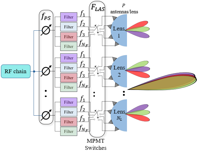
In this work, a modified \acLAS analog transceiver design is proposed to address the beam squinting problem in \acUWB \acmMIMO systems. The \acLAS design involves the use of both \acpPS and switching networks to steer the beam [12, 13]. Unlike the traditional \acLAS systems which mainly focus on increasing the field of view and steering resolution, this work leverages the combination of these two steering mechanisms (i.e., \acpPS and switches) to compensate for the beam squinting problem while maintaining the intended beamwidth performance. Mainly, \acpPS are used to steer the beam to the desired direction based on the location of the targeted user, and the switching mechanism is used to select an antenna element under the lens that can correct/minimize the deviation of the beam (due to squinting) from the intended direction. Considering the fact that beam squinting increases with the subcarrier’s frequency with respect to the system’s center frequency, in the proposed design, the wideband signal is chunked into several subbands in which the subcarriers would be derailed by relatively the same amount. This is achieved by inserting a bank of analog subband filters between \acpPS and the lenses, as depicted in Fig. 1. In order to correct the expected beam squinting for each subband, a low-complex simplified search-based precoding is proposed to select the appropriate antenna element under the lenses. The main contributions of this letter are summarized below:
-
•
A modified \acLAS design for mitigating beam squinting problem is presented and evaluated. Unlike the contemporary approaches presented in [5] and [11] that employ analog filters and extra \acpPS in their designs, our proposed design inherits the energy efficiency nature of the \acLAS structure, making it more appealing not only from affordability perspective but also for the envisioned green-communication networks.
-
•
While the proposed design can work with the traditional exhaustive search-based precoder for antenna selection under the lenses, an enhanced, threshold-based precoder is proposed to reduce the search complexity without notable degradation on the beam-gain performance.
The rest of this letter is organized as follows. The system model of the conventional \acmMIMO that leads to the beam squinting problem is recapped in Section II. Detailed explanation and analysis of the proposed \acLAS design and its proposed precoder are given in Section III, followed by the numerical evaluation in Section IV. Section V finally concludes the work.
II System Model and Problem Formulation
A \acmMIMO system with a \acBS equipped with -antennas \acULA is considered. Suppose there are channel paths arriving at the \acBS where each path is associated with a passband complex gain , \acAoA/\acAoD , and the propagation delay , where is the channel’s maximum delay spread. As briefly mentioned in Section I, for a \acmMIMO system implementing a very wideband signaling, there exists a non-trivial amount of delay across the array elements (with respect to the first element), given by [4]
| (1) |
with being inter-element spacing where is the carrier wavelength, and . Consequently, the total delay of an path observed by element can be given as
| (2) |
Accordingly, the \acCIR observed by the element is given as
| (3) |
where is the carrier frequency.
Taking the Fourier transform of (3) and simplifying, the \acCFR of the considered link is obtained as [4]
| (4) |
where is the equivalent baseband path gain. Stacking the channels from all antennas, the \acCFR vector over the whole array can be expressed as
| (5) |
where represents the Hadamard product. is the perfect spatial-domain steering vector and is a frequency-dependent vector that induces beam-squinting problem in the system. As such, modifies into a frequency-dependent effective steering vector . In the multicarrier signaling, , being frequency-dependent, directs signal pertaining to different subcarriers to different directions away from the desired direction. From (5), the effective direction of the signal at subcarrier centered at , where with and being the \acFFT size and subcarrier spacing, respectively, can be found as
| (6) |
Therefore, in order to ensure reliable performance for the practical \acmMIMO systems, the effect of should be minimized, if not completely eliminated. The transceiver design presented in the subsequent section is dedicated to minimizing the squinting problem taking complexity and energy efficiency issues into account.
III The Proposed LAS System Design
III-A Transceiver Design
This work leverages the unique design of the \acLAS transceiver presented in our earlier work [12] that gives the inherent ability to control the signal in the analog domain. The \acLAS design is modified to counteract the beam-squint problem while maintaining all advantages of the conventional LAS design. As shown in Fig. 1, the design consists of lenses, each of which equipped with antenna elements, and \acpPS, such that . Unlike the conventional \acLAS structure, the modified design features analog subband filters for chunking the wideband signal into groups of narrowband signals such that the subcarriers within each group experience approximately similar amount of squinting. It also features the \acMPMT instead of the \acSPMT switching network for relaying all the narrowband groups to their respective antennas elements (based on the degree of their squinting) under the lenses.
At the transmitter, for one \acRF chain, the \acUWB signal passes through the \acPS network where each \acPS adds a fixed delay to the incoming \acRF signal based on the desired direction 111Note that the multipath index is dropped here and in the subsequent equations just for the sake of notational simplicity.. As such, the \acPS precoder design is determined by and can be given as
| (7) |
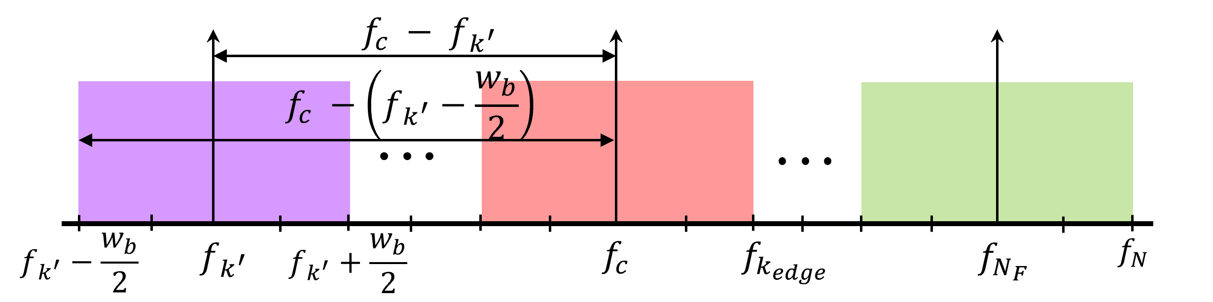
where is the distance between the lenses assumed to be . The output of each \acPS is passed through groups of analog subband filters (each group has parallel analog subband filters) to chunk the wideband signal into narrowband signals of bandwidth where and is the system bandwidth. is decided based on the amount of squint that the system can tolerate. The extreme case is to compensate the squint due to each individual subcarrier, which would require filters for the whole design. To relax the design requirement, it is assumed that the squinting within the quarter of 3 dB beamwidth is tolerable inside each subband, i.e.,
| (8) |
where is the center frequency of the filter, with , and is the carrier frequency of a subcarrier at the edge of -th subband (see Fig. 2). Using (6), (8) can be simplified to
| (9) |
For simplicity, we consider the subband centered at such that and . Consequently, (9) reduces to
| (10) | |||
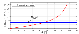
Considering that the severity of the beam squint increases as grows (equation (1)), is optimized based on the maximum scanning angle of the \acLAS system (i.e., [12]) such that it is applicable for all users within the scanning range (See Fig. 3). This leads to
| (11) |
Each narrowband signal passes through the switching mechanism using \acMPMT switches modeled by a precoder to the lenses for transmission. The \acMPMT switches allow simultaneous activation of (one for each subband) antennas under each lens. is given as
| (12) |
where is a antenna selection vector at -th lens element and . The -th element in is used to activate the -th antenna element for an incoming -th subband’s signal. The activated -th antenna element produces a beam at direction where as explained in [12].
Eventually, the effective \acRF precoder, , for the proposed design is and its -th element is obtained as as explained in [12].
Let be the -th subband’s effective beam direction given by the proposed \acLAS design with arbitrary values of ’s across the lenses, then the maximum beam gain of the design at -th subband is obtained as
| (13) |
For each subband, the proposed design seeks to find the set that gives optimum , i.e., . This can be done by the exhaustive search approach whose complexity for each subband can be quantified as .
III-B Proposed Threshold-based Precoding
In order to reduce the complexity of the exhaustive search approach, a threshold-based search mechanism is proposed. In this case, a threshold is specified (based on the desired performance) to allow the selection of a sub-optimal set of antennas over the lenses for a given -th subband. Once the sub-optimal set that satisfies the specified threshold is found, the search process continues with the next subband. This avoids the searching over all () possible combinations of the antenna under all lenses for a given subband, thereby reducing the complexity.
In the proposed precoder, it is assumed that, for the middle subband (i.e., ) the beam deviation within specific threshold (i.e., of the desired beam direction) is acceptable. Since different subbands experience different amounts of squint, the threshold is scaled based on with respect to . Hence, the search seeks to find a sub-optimal set of antennas that satisfy for -th subband. Since the squint causes beam deviation from the desired direction , the search process for a given subband begins around by setting the initial beam direction under the lenses as . Since each subband has a different amount of squinting, the combination of ’s that makes up the optimum set is unique for each subband. Therefore, such a combination can be removed from the search sets of the next subbands, thereby reducing the searching complexity even further. Note that, with the initialization approach proposed above, the subband with the least squinting converges faster. As such, the searching process is initialized from the middle to the edge subbands to reduce the size of the search sets at the edge subbands.
The proposed \acLAS design with its precoding are summarized in Algorithm 1.
IV Numerical Results and Discussion
In this section, performance of the proposed design is analyzed in terms of beam gain, precoder complexity, capacity, and power consumption. Unless stated otherwise, the numerical values of the used system parameters are GHz, GHz, , , , , the number of \acRF chains , , , and path gain follows the complex normal distribution .
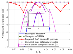
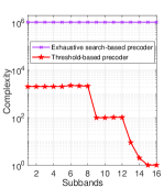
The achievable beam gain with the proposed \acLAS design is given in Fig. 4, bench-marked with the systems with full and zero beam squint as well as with [11]. The beam gain provided by the proposed design is analyzed with both full exhaustive search and the proposed threshold-based search approach. While both cases significantly improve the gain (to less than 3 dB of the ideal performance), the exhaustive search, as expected, performs relatively better, though at the expense of the high complexity as analyzed in Fig. 5(a). Fig. 5(a) shows a huge difference in complexity between the exhaustive search (which is in the order of millions) and the proposed threshold-based precoder (only hundreds to few thousands) at each subband. This is due to the simplified searching mechanism adopted by the proposed precoder as explained in Section III-B.
Next, the power consumption of the proposed design is analyzed and compared with other related designs in the literature. The power consumption model of the proposed \acLAS design is divided into four parts, given as
| (14) |
where is the transmitted power [12], , , and are power efficiencies of the amplifier, switches, and subband filters, respectively, with and being insertion losses of the switches and the filters. , , and are the power consumption of \acPS, \acMPMT switch, and \acRF chain, respectively. In our analysis, we consider , dB, mW, and mW as used in [12].
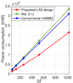
Since the values of are only available for the few ports \acMPMT switches, we model the -poles -throws \acMPMT switch considered in our design as a series of \acSPMT switches for each pole for power consumption analysis. Therefore, the term in (14) becomes , where mW is the power consumption of an \acSPMT switch [12]. The calculated power consumption for different array size is summarized in Fig. 5(b). The performance is compared with that of the conventional \acmMIMO system as analyzed in [12], and with reference [11] which also presents subband-based beam squinting compensation design. Note that, the power consumption model for the design presented in [11] follows (14) excluding the switching related terms. It is clear from Fig. 5(b) that the proposed \acLAS design is the most power-efficient design while profitably compensating for the beam squinting, which makes it suitable for commercial applications of \acmMIMO networks.
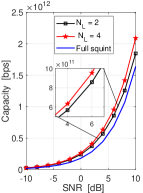
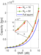
Fig. 6 gives some insights regarding the effects of the design parameters and on the system capacity of the proposed design. Regarding the point-to-point link scenario with the single-antenna receiver considered in this work, the system capacity is evaluated as [14]
| (15) |
where is the SNR and is the expectation operation. Fig. 6(a) shows that there is slight capacity improvement as increases. We reckon that this improvement stems from increasing the controllablity of the resultant beam as increases. Fig. 6(b) shows that the system performance improves slightly with the increase in , which is plausible due to the fact that as increases, the subband sizes decreases, leading to less residual squint within each subband. However, a large number of filters increases the system’s power consumption. Therefore, the choice of in (11) should consider the power efficiency issue as well, which is left for future work.
V Conclusion
In this paper, a novel analog transceiver design based on the LAS architecture and subband filters is proposed to compensate for the beam squint effect in UWB mMIMO systems. While the proposed design works well with the traditional exhaustive search-based precoder, a less complex, threshold-based precoding technique is also proposed. Simulation results demonstrate that the proposed LAS-based transceiver design provides good system performance with both the full and threshold-based simplified exhaustive search precoding. Although the proposed design can be implemented with off-the-shelf components, in practice, high-quality narrowband filters should be used to ensure better performance. Research on such filters for higher frequency bands is ongoing [15]. Extension of the proposed design to multi-user scenarios with hybrid precoding is left for future work.
References
- [1] S. A. Busari et al., “Millimeter-wave massive MIMO communication for future wireless systems: A survey,” IEEE Commun. Surveys Tuts., vol. 20, no. 2, pp. 836–869, 2017.
- [2] D. Cassioli et al., “The ultra-wide bandwidth indoor channel: From statistical model to simulations,” IEEE J. Sel. Areas Commun., vol. 20, no. 6, pp. 1247–1257, 2002.
- [3] F. Liu et al., “Joint radar and communication design: Applications, state-of-the-art, and the road ahead,” IEEE Trans. Commun., vol. 68, no. 6, pp. 3834–3862, 2020.
- [4] B. Wang et al., “Spatial-wideband effect in massive MIMO with application in mmWave systems,” IEEE Commun. Magazine, vol. 56, no. 12, pp. 134–141, 2018.
- [5] Z. Liu et al., “Minimize beam squint solutions for 60 Ghz millimeter-wave communication system,” in Proc. 78th Veh. Technol. Conf. (VTC Fall), Las Vegas, NV, 2013, pp. 1–5.
- [6] M. Cai et al., “Effect of wideband beam squint on codebook design in phased-array wireless systems,” in Proc. IEEE Global Commun. Conf. (GLOBECOM), Washington, DC, 2016, pp. 1–6.
- [7] H. Yu et al., “Performance analysis and codebook design for mmWave beamforming system with beam squint,” IEEE Wireless Commun. Lett., 2021.
- [8] X. Liu and D. Qiao, “Space-time block coding-based beamforming for beam squint compensation,” IEEE Wireless Commun. Lett., vol. 8, no. 1, pp. 241–244, 2018.
- [9] I. Laurinavicius et al., “Beam squint exploitation for linear phased arrays in a mmWave multi-carrier system,” in Proc. IEEE Global Commun. Conf. (GLOBECOM), Waikoloa, HI, 2019, pp. 1–6.
- [10] G. Li et al., “Beam squint compensation for hybrid precoding in millimetre-wave communication systems,” Electron. Lett., vol. 54, no. 14, pp. 905–907, 2018.
- [11] Z. Sattar et al., “Antenna array gain and capacity improvements of ultra-wideband millimeter wave systems using a novel analog architecture design,” IEEE Wireless Commun. Lett., vol. 9, no. 3, pp. 289–293, 2019.
- [12] M. Karabacak et al., “Lens antenna subarrays in mmWave hybrid MIMO systems,” IEEE Access, vol. 8, pp. 216 634–216 644, 2020.
- [13] ——, “Hybrid MIMO architecture using lens arrays,” Jul. 14 2020, US Patent 10,714,836.
- [14] S. Gherekhloo et al., “Hybrid beamforming design for downlink MU-MIMO-OFDM millimeter-wave systems,” in Proc. IEEE Sens. Array Multichannel Signal Process. Workshop (SAM), Hangzhou, China, 2020, pp. 1–5.
- [15] N. Qorvo Inc., Greensboro, Advanced BAW filter technology and its impact on 5G. [White paper]. Qorvo, 2020.