Sequential Manipulation Planning on Scene Graph
Abstract
We devise a 3D scene graph representation, contact graph+ (), for efficient sequential manipulation planning. Augmented with predicate-like attributes, this contact graph-based representation abstracts scene layouts with succinct geometric information and valid robot-scene interactions. Goal configurations, naturally specified on contact graphs, can be produced by a genetic algorithm with a stochastic optimization method. A task plan is then initialized by computing the Graph Editing Distance (GED) between the initial contact graph and the goal configuration, which generates graph edit operations corresponding to possible robot actions. We finalize the task plan by imposing constraints to regulate the temporal feasibility of graph edit operations, ensuring valid task and motion correspondences. In a series of simulated and real experiments, robots successfully complete complex sequential object rearrangement tasks that are difficult to specify using conventional planning language like Planning Domain Definition Language (PDDL), demonstrating high potential of planning sequential manipulation tasks on .
I Introduction
Autonomous robots, expected to conduct a wide range of complex sequential manipulation tasks in challenging environments, ought to have adept planning capabilities. At the task level, robots need to search for a feasible action sequence in a domain, critical for long-horizon tasks involving multiple steps. At the motion level, robots have to produce continuous trajectories by incorporating physical constraints. Yet to date, thoughtfully defining the planning domain at the task level while clearly specifying environmental states at the motion level remains a time-consuming and error-prone process with conventional methods. Despite excelling in expressing symbolic states and abstract actions, STRIPS-like representations (e.g. PDDL) struggle with continuous states like geometric information obtained by the perception module. This deficiency calls for alternative approaches other than STRIPS-like planners, especially for long-horizon manipulation tasks involving complex, nested specifications.
Recently, 3D scene graph emerges as a holistic scene representation for scene modeling [1, 2, 3, 4, 5, 6, 7, 8, 9, 10, 11, 12, 13], object part modeling [14, 15], kinematic relations [16, 17], robot manipulations [18, 19, 20, 21, 22], and human-robot teaming [23, 24, 25]. In particular, Contact Graph () [11] reflects the whole kinematic relations detected in the scene using 3D vision, useful for robot motion planning [26]. In this paper, we further identify that such a can also serve as a description of tasks, thus becoming a carrier of various information related to both task domains and motion constraints. Since can be directly and robustly built from perceptual input [11], planning manipulation tasks on naturally bridges robot perception and execution by organizing scene entities, effectively anticipates action outcomes by updating graph, and easily validates physical feasibility by maintaining geometric information.
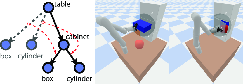
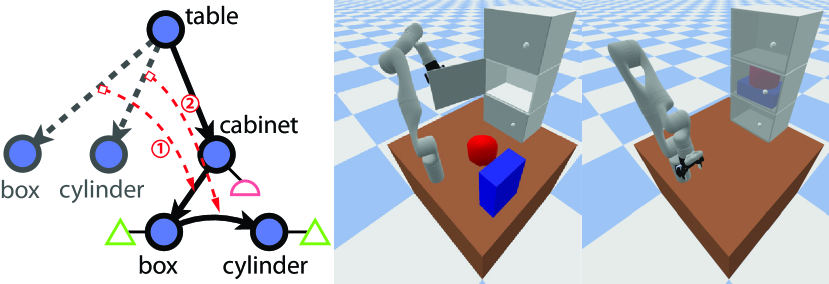
Given the current environment represented as a , if one could also specify the goal configuration on a , a straightforward idea to generate a task plan is to adopt Graph Editing Distance (GED). Specifically, a GED algorithm finds a set of graph edit operations (e.g., inserting and deleting edges) to transform a graph into another. A sequence of feasible graph edit operations naturally corresponds to a set of robot actions, forming a task plan. For instance, deleting an edge and inserting a new one is analogical to picking an object and placing it elsewhere; see Fig. 1. However, two challenges have to be addressed.
(i) Temporal Dependency. Some graph edit operations (or robot actions) are invalid until certain prerequisites are met. For instance, in Fig. 1a, to represent the task of putting the Box in the Cabinet, it is valid to delete the edge between Table and Box and insert one below Cabinet in graph editing. However, such an operation is infeasible neither in task nor in motion before the cabinet door is open.
(ii) Goal Configuration. Computing GED requires a valid graph representing the goal configuration. How do we validate whether the goal is physically plausible and produce alternatives when it is not? Fig. 1a depicts a scenario where the Cabinet’s volume cannot fit the Box when the Cylinder is placed side by side; valid solutions only exist if one is placed on top of the another.
To tackle these two challenges, we first extend the to (see Fig. 1(b)) by augmenting predicate-like attributes to constrain feasible operations. These attributes are task-specific: They could be predicates/rules in conventional task planners or entities’ geometric descriptions naturally defined on graphs. Next, we devise a genetic algorithm for graph structure and a stochastic optimization method for object poses to construct the goal configuration. To solve the temporal dependency problem, we develop a topological sorting algorithm based on GED to search for a sequence of graph edit operations on constrained by nodes’ attributes, corresponding to the robot’s task plan.
In simulation, we demonstrate the proposed graph-based planning scheme in complex sequential manipulation tasks. An experiment further verify the feasibility of the produced task and motion plans in physical environments. Our contributions are three-fold: (i) Our augmented graph-based representation abstracts symbolic forms from 3D perceptual input for task planning while maintaining geometric information for motion planning. (ii) We devise a suite of efficient algorithms for planning complex sequential manipulation tasks on . (iii) We demonstrate the potential of using scene graphs as a general representation to organize multiple information sources (e.g., perception, expert knowledge, predicates) and to unify scenes, tasks, and goals.
I-A Related Work
Many effective representations or programming languages have been devised for Task Planning, such as STRIPS [27], hierarchical task network [28], temporal and-or-graph [9, 24, 21, 29], Markov decision process [30], and PDDL [31]. Among them, PDDL is a milestone that standardizes task planning. However, PDDL requires thoughtful designs for complex tasks, which in some cases could become complicated in large planning domains. Although newer versions of PDDL [32, 33, 34] introduced new features to consider more complex planning domains and problems or simplify the domain specification, it is primarily restricted to discrete symbolic variables. Although one of the most up-to-date PDDLs, PDDLStream [35], incorporates sampling scheme to deal with high-dimensional and continuous variables, it still requires sophisticated domain-specific functions to process geometric information for related predicates during planning.
While task planning [36] or motion planning [37] alone could be effectively solved nowadays, integrating these two into Task and Motion Planning (TAMP) [38] remains challenging. Researchers attempt to tackle this problem from various angles, such as incorporating motion-level constraints to the task planning [39, 40, 41, 35], developing interfaces that communicate between task and motion [42], or inducing abstracted modes from motions [43, 44]. One of the most critical questions is how to scale up for more complex tasks or environments. Our work demonstrates the feasibility of task planning on scene graph representations that naturally represent environmental states, objects geometry, and task goals, efficient for instantiating task plans to motion level.
I-B Overview
We organize the remainder of this paper as follows. Section II introduces the proposed graph-based representation, , and defines attributes. Section III details the method for goal configuration synthesis, and Section IV introduces the proposed planning schema built on top of with GED. Section V further verifies the efficacy of scaling to high-dimensional and complex environment. We conclude the paper with discussion in Section VI.
II Graph-based Scene Representation
Building on top of [11] representing a 3D indoor scene, is augmented as attributes with extra contextual cues for robot planning on complex sequential manipulation tasks.
II-A Contact Graph
Formally, a includes (i) a scene parse tree that hierarchically organizes scene entities (e.g., objects with their articulated parts) based on supporting relations , and (ii) proximal relations (e.g., collision) among entities represented by undirected edges.
Scene Entity Nodes include: (i) the scene node , serving as the root of , and (ii) a set of non-root nodes ; each encodes a unique instance label , a semantic label , a full geometry set of geometry primitives (a triangular mesh or a CAD model), and an oriented 3D bounding box .
Supporting Relations is a directed edge between the parent node and the child node : , indicating stably supports with sufficient contact areas.
Proximal Relations introduce links among entities in the . It imposes additional constraints by modeling spatial relations between two non-supporting but physically nearby objects: Their meshes should not penetrate each other. Proximal relations are only assigned to geometry pairs to enable collision checking and reduce computational costs. The non-penetration constraints are triggered when finding geometrically feasible object poses:
| (1) |
where is the signed distance between and [45], and is a set of all geometry primitive pairs for collision detection.
II-B Contact Graph+ ()
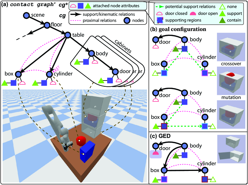
Representing 3D environments by [11] is insufficient to support planning due to the lack of temporal dependency and goal configuration. Here, we augment it to ; see Fig. 2. While and follow the aforementioned definitions, is the set of task-dependent attributes with augmented to a scene entity node , which constrain the possible interactions with the node.
Henceforth, we consider an object rearrangement task with two attributes: (i) a supporting attribute indicates how objects physically support others, and (ii) a status attribute indicates a container’s accessibility. Similar to predicates in PDDLs, the attributes of nodes in can carry more sophisticated information for other complex tasks.
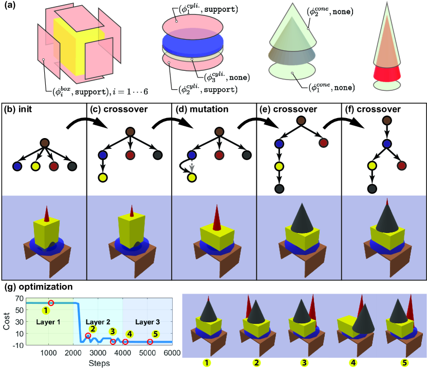
Fig. 3a shows examples of supporting attributes for different shapes. Specifically, the supporting attribute indicates if an object can support another, where is a set of surfaces extracted from that would possible serve as a supporting surface. is modeled as a region with a closed boundary and is realized as a 2D signed distance field , where is in the interior region , in the exterior region , and on the boundary [46]. The value of is the minimum Euclidean distance from to . are the supporting types:
-
•
support indicates that a stable supporting relation can be formed between and if two nodes satisfy
(2) where is defined as a convex hull of an overlapping region between a child node and its parent node ’s supporting region . projects Center of Mass (CoM) of and all its descendants onto the same plane as , and is the gravitational vector; we assume all supporting planes are perpendicular to . indicates the gravitational moment exerted on cannot be canceled by its support and result in unstable .
-
•
contain is a step further to support. In addition to satisfying Eq. 2, the bounding box of should contain the union of bounding boxes for and all its descendants:
(3) where is a subtree of rooted at .
-
•
none indicates that no support or contain relations could be established between the two nodes.
The status attribute determines whether the objects descended from a node with contain attribute (i.e., being contained) are accessible.
is the assigned attribute to node , wherein is an optional attribute only assigned to containers. The supporting relation is further augmented with supporting region and kinematic information : . is the pose vector pointing from to , where is the Degree of Freedom (DoF) of w.r.t. ; it could also be considered as the plausible transformation between the parent and the child nodes. is a supporting attribute from the parent node to establish the supporting relation . Of note, a single node is possible to have more than one supporting attribute in , which affords to partition working space on the same node for more sophisticated tasks.
II-C Problem Definition
We define the problem of planning on in two phases. Assuming a rough goal configuration is provided (e.g., putting the box and the cylinder into the cabinet; see Fig. 2bc), the first phase resolves the violations of physical constraints defined in Section II-B. To modify and discover a plausible , we integrate a genetic algorithm to produce the structure of supporting relations among objects and a stochastic optimization method to generate their poses that satisfy physical constraints imposed on both and . Section III describes goal configuration discovery.
We utilize GED to find an optimal set of graph edit operations to transform from the current environment represented by to the goal configuration , along with imposed temporal dependencies between operation pairs (e.g., opening cabinet door before placing objects inside); see Fig. 2d. Section IV details this procedure.
III Goal Configuration Discovery
A planning process requires a known goal configuration. Although defining one as a is relatively straightforward, automatically finding a plausible goal configuration satisfying all physical constraints is still preferred.
Assuming a rough goal is specified (see Fig. 3b), we aim to find a configuration incorporating proper supporting and proximal relations ( and ) among objects. For a , its configuration is represented by , and its configurations space is defined as , where is the attribute space, and is the object poses’ total DoFs. Directly sampling a configuration of in may not always produce valid configurations. We address this problem by using (i) a genetic algorithm to generate a ’s structure in to discover supporting relations, and (ii) a stochastic optimization method to optimize the object poses in to obtain valid proximal relations.
III-A Supporting Structure Synthesis
Genetic algorithms have demonstrated its capability of searching complex tree structures for symbolic regression [47, 48]. It consists of two basic operations, crossover and mutation, which randomly modify the edges and nodes over generations to increase diversity in a population. In addition, a fitness function is defined as a heuristic to select preferred tree structure over the population. In this paper, we adopt a genetic algorithm for our structure generation. Specifically,
-
•
Crossover breaks a supporting relation and transplants with all its descendants to another parent , as long as is not ’s descendant, and the new supporting relation satisfies constraints imposed by the supporting attribute . Fig. 3 illustrates some Crossover operations.
-
•
Mutation first randomly selects another set of supporting attributes for a random node . Next, it chooses a for possibly better supporting of its descendants or larger space for maintaining proximal relations with its surrounding objects.
We design a Fitness score as a search heuristic to speed up the supporting synthesis:
| (4) |
where is a threshold of area occupation. Intuitively, no more objects can be placed on the parent node if the contact area between the parent node and its child node(s) is larger than , and the algorithm would incline to move the child node(s) away. Fig. 3b-f depicts an example of how a valid supporting structure in is found by the algorithm. Next, we describe how to find a detailed configuration with specified object poses.
III-B Object Pose Synthesis
The objects’ poses in a valid should satisfy Eq. 1, i.e., not penetrating each other. With a hinge loss function
| (5) |
we penalize the signed distance between objects and , and is a safety distance among them. if , and if and are in collision. We formulate the object pose synthesis as an optimization problem:
| minimize | (6) | |||
| subject to | (7) |
We can further impose constraints for support or contain (i.e., Eqs. 2 and 3) to this optimization process. To solve this optimization efficiently, we design an update scheme:
| (8) | ||||
| (9) |
Eq. 8 is a weighted sum over pose vectors defined in Eq. 9 between two objects, whose weights are proportional to the signed distance loss (Eq. 5). This design implicitly pushes object away to resolve collision or increases safety distance.
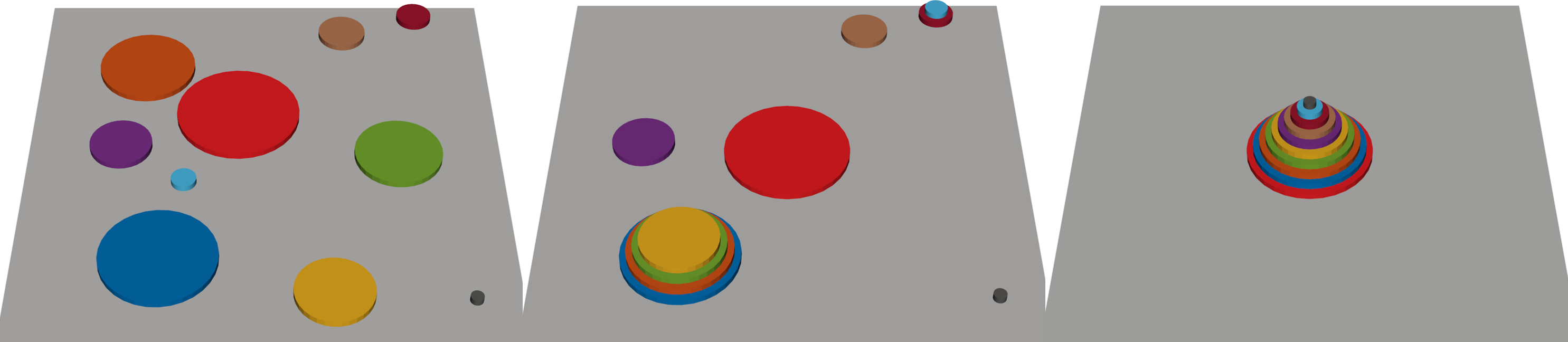
We further add stochasticity to avoid local minima. The update direction of optimization is , where is the step size, is a pose vector which is concatenated by objects poses for optimization, is the proposal distribution to be sampled from, and is the direction for the next sample. adds noise to the sampling direction; it decays at the rate in each iteration, which reduces randomness in sampling process as iteration increases. The optimization is realized iteratively in a breadth-first manner; see Algorithm 1. Fig. 3g shows an example of the pose synthesis process. In Layer 1, only one object is in the lowest level (disk) and the highest layer (grey cone), whose poses are found quickly. The convergence is slower in Layer 2 as the box and the red cone should not collide with each other while staying within the disk.
IV Planning on
We detail our planning framework based on for a single agent (e.g., a single manipulator), assuming a large swap node (e.g., a table) is available to temporarily place objects. First, the planning framework leverages GED to find an initial action set. Next, the action set and temporal dependencies among actions are constructed incrementally by reasoning about physical commonsense in terms of accessibility, stability, and collision. Finally, a valid action plan is found through the topological sort.
IV-A Graph Edit Operations
The concept of GED [49] is first introduced to measure the similarity between two graphs. It finds a set of graph edit operations that transform a graph into another while minimizing the total editing cost. We define GED between the initial scene and the goal configuration as
| (10) |
where is the cost function of an edit operation , and is a set of edit operations transforming to . We consider four types of edit operations and correspond them to robot actions:
-
•
delete() Pick(, ): Pick an object from .
-
•
insert() Place(, ): Place an object on .
-
•
substitute(, opened) Open(): Open the door such that edges among contained objects are editable.
-
•
substitute(, closed) Close(): Close the door such that edges among contained objects are uneditable.
We use the GED algorithm [50] to find containing a set of edit operations that transforms to ; edit operations are referred to as robot actions henceforth.
IV-B Temporal Dependency
Although the robot action set provides elements for planning, generating feasible plans requires valid temporal dependencies. We build up a partially ordered set by imposing temporal dependencies onto certain pairs of robot actions . We consider three types of dependencies.
Action Precedence
Some actions should take place before others. For instance, an object has to be picked before it can be placed: , and the parent object must be placed before placing others on the top of it: .
Spatial Feasibility
Some objects should be cleared before performing the action. For instance, re-orientating a parent node (e.g., flip a box upside down) requires all its descendants to be placed elsewhere (e.g., a swap node ):
|
|
Accessibility
It is prohibited to interact with others inside a closed enclosure, i.e., editing the edges among all its descendants. For instance, an Open action should precede all related graph edit operation in ,
IV-C Topological Sort
Given , the task planning problem on becomes a topological sorting problem on to produce a valid action sequence . To solve it, we define a search node , where is the set of actions remains unexplored, is the set of temporal dependencies not imposed yet, the selected action reaching current search node, and the graph structure after executing . At the start node, and are given by Section IV-B. contains actions that do not have precursors, available for exploration of neighbors.
The representation is advantageous for evaluating geometric feasibility (e.g., collision) during task planning. Specifically, each action is parametrized by the object poses with geometric information encoded in the nodes, enabling collision detection during planning. Compared to PDDL definitions, which have to checks all the pair-wise relations, the representation maintains object relations over hierarchical structures and evaluates geometric feasibility only on edited node and its related nodes (e.g., descendants). The infeasibility can be resolved by (i) moving the object to the swap node instead of directly to its goal, (ii) adding new actions to that move the object back to the goal, and (iii) imposing necessary temporal constraints to clear objects that would collide along the way. The unspecified intermediate goals can be found by reiterating the pose synthesis algorithm in Section III-B. Our searching pipeline is implemented as a depth-first-search-based topological sorting algorithm, and the object poses are optimized along with the collision checking process during the search.
V Simulations and Experiments
In simulations, we characterize the algorithms supporting our graph-based planning framework by time complexity in an object stacking task. We further demonstrate that our framework can handle a complex sequential manipulation task. In the experiment, we use a physical robot manipulator in a setup similar to Fig. 1. The code and environment are available at https://sites.google.com/view/planning-on-graph.
V-A Simulated Object Stacking
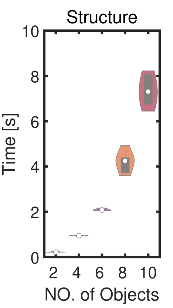
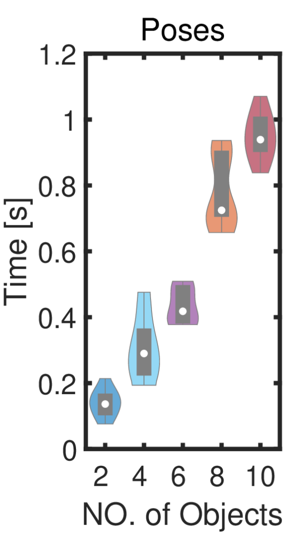
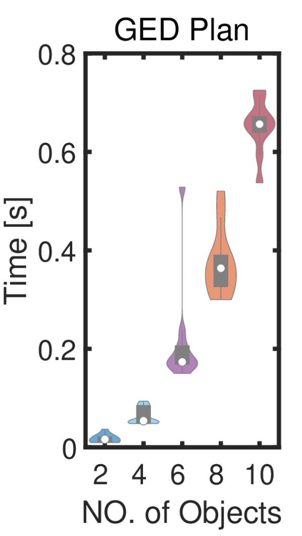
We design an object-stacking task to evaluate the time complexity of the proposed framework, especially when facing complex scenarios. In this task, an agent stacks, through symbolic actions, the plates on the table from large to small; Fig. 4(e) shows a typical example of this task’s initial and goal configurations with ten plates.
While the task appears to be simple, stacking each object requires Pick and Place that account for pair-wise constraints in terms of object size. Hence, its complexity quickly increases as the number of objects increases. Our framework needs three steps to solve this problem: (i) synthesizing structure (i.e., supporting relations) among objects from large to small, (ii) synthesizing specific object poses such that the smaller object on top is within the larger one, and (iii) producing a complete task plan by GED.
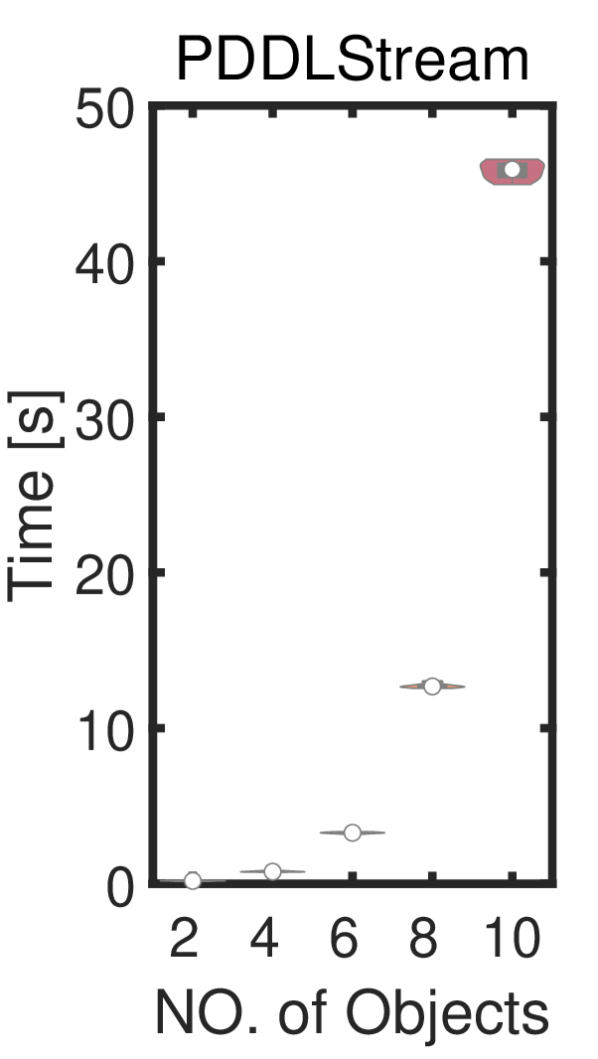
We also implement a baseline using an existing task planning method. Classic PDDLs do not contain object geometric information and fail to handle the pair-wise constraints in terms of object size. Here, we implement a PDDLStream, capable of considering object poses by incorporating samplers in PDDL domains. We define two streams that (i) sample poses of an object supported by another, and (ii) test collision between two objects given their poses. We choose the default adaptive algorithm provided by the PDDLStream. The goal for both the baseline and our method is implicitly defined as pair-wise constraints in terms of object sizes: A smaller object must be placed above a larger object, resulting in only one valid goal configuration. The simulation is repeated 10 times for 2, 4, 6, 8, and 10 objects with randomly initialized object poses. The computing hardware is a Ubuntu 20.04 desktop with an AMD 5950x processor.
Figs. 4(a), 4(b), 4(c) and 4(d) show the simulation results. For the baseline method, the time requirement of finding a valid solution using PDDLStream grows exponentially (Fig. 4(d)) as the number of object increases since it needs to explore all valid combinations of actions and objects in the search space.
In comparison, the proposed framework achieves the goal through three steps: synthesizing structure of supporting relations (Fig. 4(a)), synthesizing object poses (Fig. 4(b)), and planning with GED (Fig. 4(c)). By leveraging the representation, the genetic algorithm only explores the graph structures that are more likely to produce a feasible solution, which successfully reduces the search space and is especially advantageous when the setup is more complex. Still, the majority of time is spent on synthesizing structure due to the large space of plausible graph structures. Overall, the proposed method is significantly more efficient than PDDLStream when the environments are complex (i.e., more than six objects), whereas PDDLStream is at similar performance (slightly better) when the scenarios are simple (i.e., six or fewer objects). This result indicates that the proposed framework can scale up much better compared with PDDLStream.
V-B Simulated Complex Task
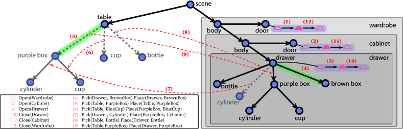
We qualitatively demonstrate that our graph-based planning scheme can handle a complex sequential manipulation task. The task is to put Cup, Bottle, and PurpleBox on a table inside a drawer. The challenges are two-fold: (i) Since the BrownBox and the Cylinder are already inside the confined Drawer, the objects must be rearranged properly (i.e., synthesize a valid goal configuration) to fit in the tight space. (ii) The Drawer is contained by the Cabinet, who is also contained by Wardrobe, demanding a feasible plan with the correct temporal dependency when reaching for the objects inside the drawer.
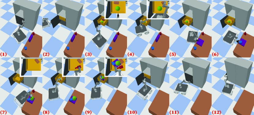
Fig. 5(a) shows the produced task plan and depicts the corresponding graph edit operations on the . Of note, most operations consist of two actions—Pick and Place. The corresponding keyframes in the task execution using a mobile manipulator (a Husky mobile base and a UR5 arm) are visualized in Fig. 5(b), whose motions are planned using a Virtual Kinematic Chain (VKC) modeling method [52, 26].
Resulting produced using the representation reflect three advantages. First, the robot produces a temporally correct plan by exposing three levels of containment and closing them afterward; see Fig. 5(b)(1–3) and (10–12). These nested relations are not trivial to define by predicates; they are naturally expressed in due to its hierarchy. Second, the plan contains critical steps of rearranging objects. For instance, move the BrownBox to the side in the Drawer (Fig. 5(b)(4)) and place the Bottle flat (Fig. 5(b)(8)), so that the large PurpleBox could fit in the confined space. These capabilities demonstrate the efficacy of goal configuration synthesis, facilitated by the geometric information encoded in . Third, the task plan is very efficient—the robot can make the best use of the PurpleBox to support the Cup and the Cylinder, so that they can be moved together and minimize motion costs. Achieving this using PDDLStream would require tedious definitions of object pair-wise relations and complex descriptions of objects for sampling.
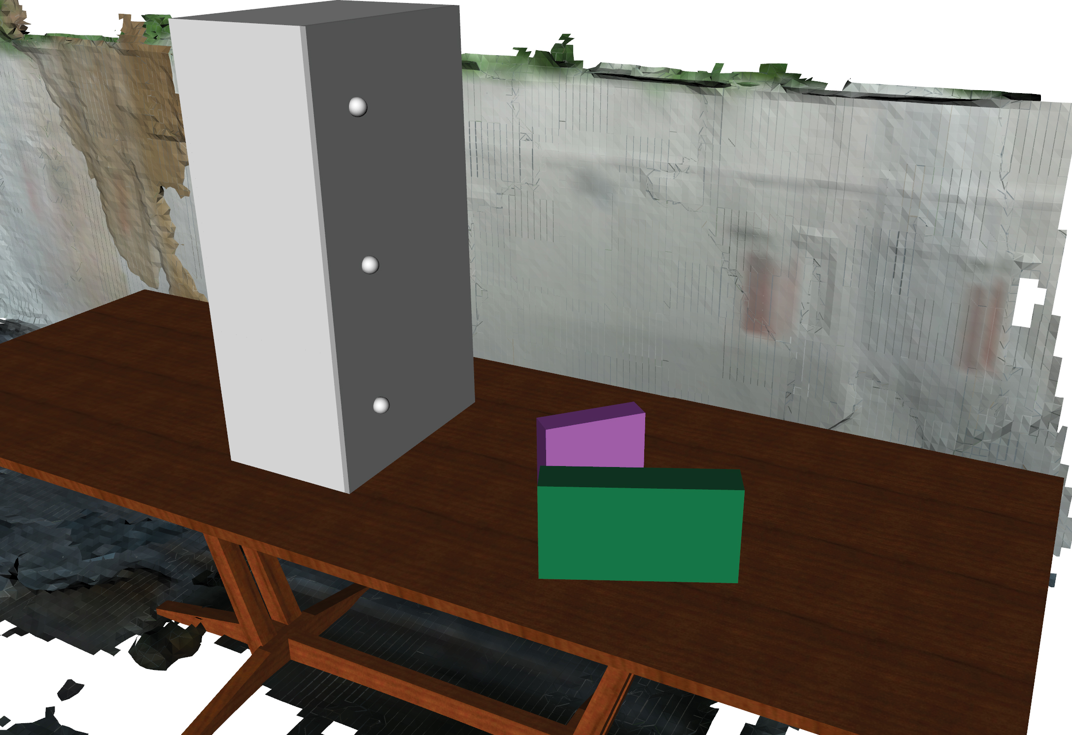
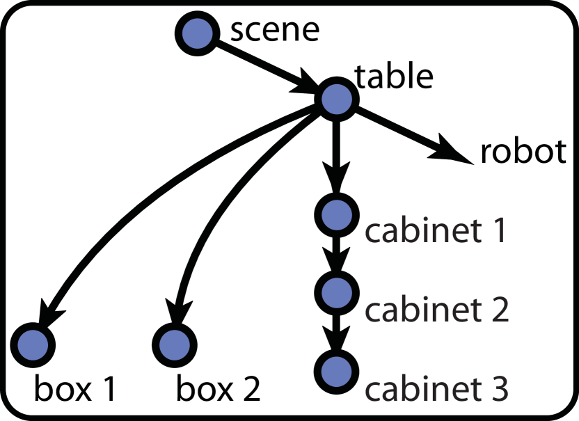
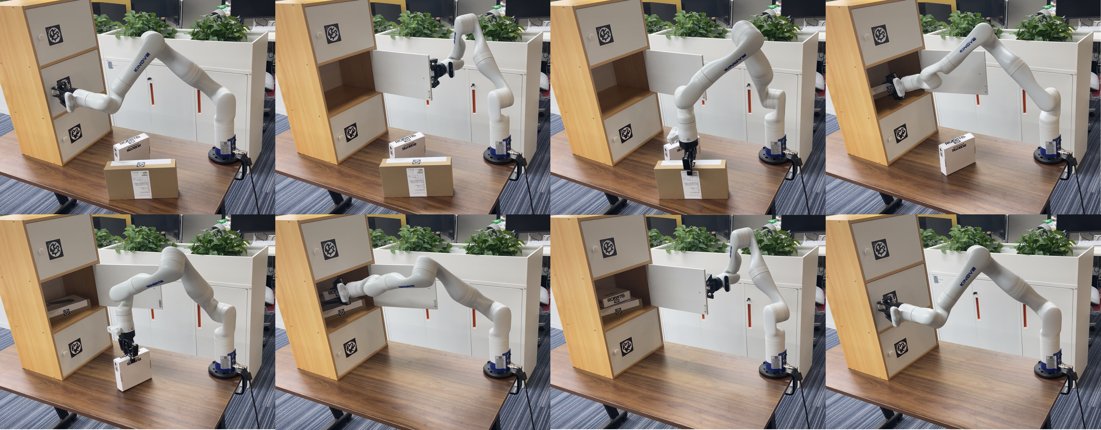
V-C Experiment
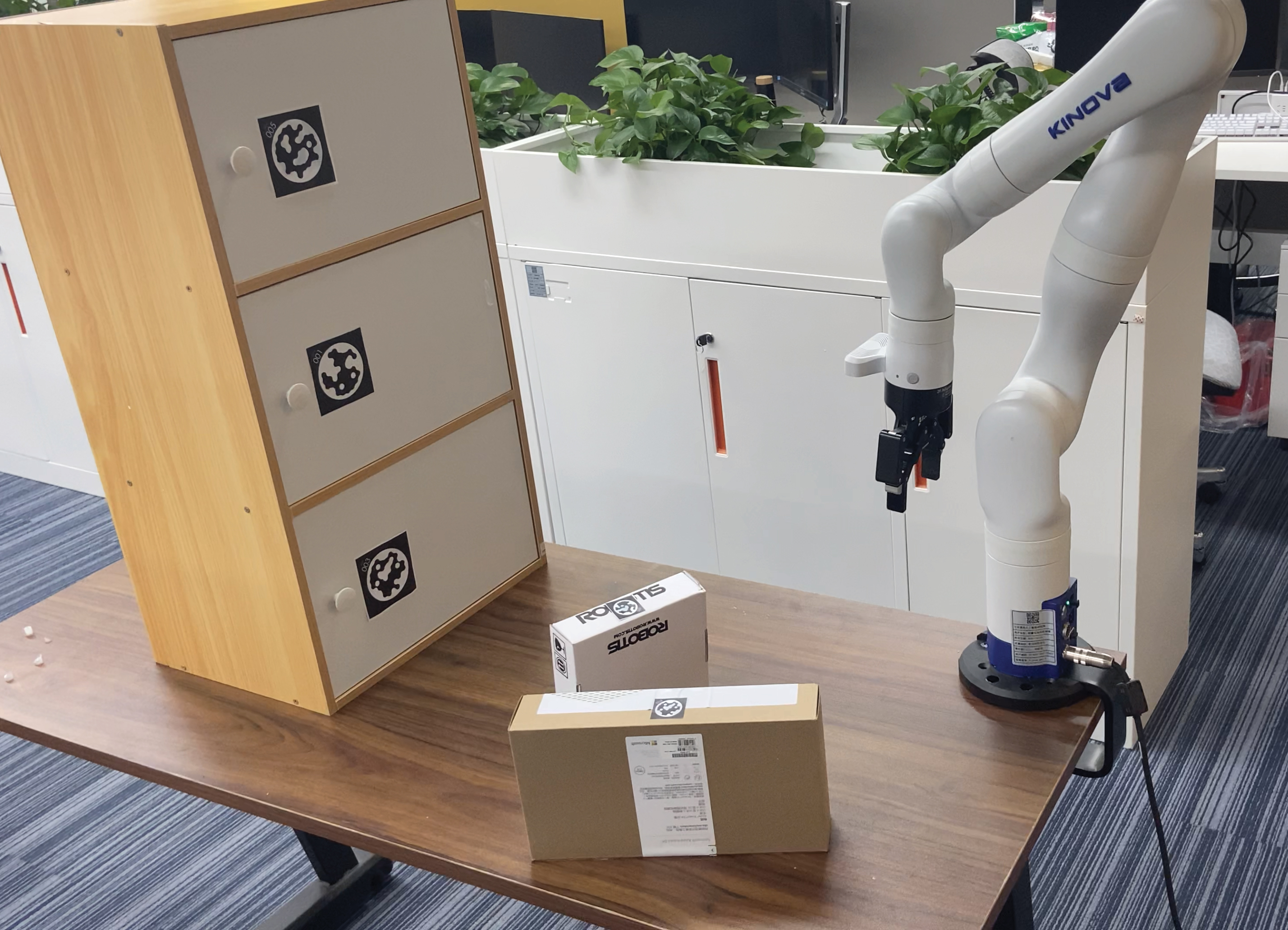
We demonstrate in organizing information from scene reconstruction and performing manipulation planning in physical environment. The experiment is conducted with a Kinova Gen 3 manipulator on a table-top environment; see setup in Fig. 6(a), wherein the manipulator is tasked to place the two boxes on the table to the second cabinet. We reconstruct the scene [11] and replace cabinets and boxes with CAD models (Fig. 6(b)). After generating contact graph (Fig. 6(c)), the planned sequence on is shown in Fig. 6(d). As the two objects cannot fit into the cabinet side-by-side, the robot stacks the smaller object onto the larger one. Of note, the robot exhibits correct temporal order of executions for both cabinet opening and object stacking.
VI Discussion and Conclusion
We tackled two challenges in manipulation planning for complex sequential tasks on contact graph—synthesizing plausible goal configurations and enforcing temporally correct graph edit operations. The former was addressed by a genetic algorithm that synthesizes the supporting relations among objects and a stochastic optimization method that produces objects’ poses. The latter was converted to a topological sorting problem on the set of computed graph edit operations and imposed action temporal dependency defined by predicate-like attributes on . Our simulations and experiments demonstrate that the proposed planning scheme can scale up more efficiently compared with PDDLStream and handle spatially and temporally complex tasks whose planning domain could be hardly defined.
The proposed representation and the planning scheme are by no means a perfect solution for alleviating manual efforts completely in general settings. Rather, we aim at justifying the potential of developing planning scheme based on scene graph, which is fruitful for advancing robot autonomy by sharing a representation with perception and by relieving efforts in domain specification (e.g., those in PDDLs). A future direction of the proposed framework is to handle uncertainty in robot perception and execution, which by itself is a large topic [53, 54, 55]. Scene graph representations, however, may afford new perspectives toward this problem.
References
- [1] S.-C. Zhu and D. Mumford, “A stochastic grammar of images,” Foundations and Trends in Computer Graphics and Vision, vol. 2, no. 4, pp. 259–362, 2007.
- [2] Y. Zhao and S.-C. Zhu, “Image parsing with stochastic scene grammar,” in NeurIPS, 2011.
- [3] Y. Zhao and S.-C. Zhu, “Scene parsing by integrating function, geometry and appearance models,” in CVPR, 2013.
- [4] S. Qi, Y. Zhu, S. Huang, C. Jiang, and S.-C. Zhu, “Human-centric indoor scene synthesis using stochastic grammar,” in CVPR, 2018.
- [5] C. Jiang, S. Qi, Y. Zhu, S. Huang, J. Lin, L.-F. Yu, D. Terzopoulos, and S.-C. Zhu, “Configurable 3d scene synthesis and 2d image rendering with per-pixel ground truth using stochastic grammars,” IJCV, vol. 126, no. 9, pp. 920–941, 2018.
- [6] S. Huang, S. Qi, Y. Zhu, Y. Xiao, Y. Xu, and S.-C. Zhu, “Holistic 3d scene parsing and reconstruction from a single rgb image,” in ECCV, 2018.
- [7] Y. Chen, S. Huang, T. Yuan, S. Qi, Y. Zhu, and S.-C. Zhu, “Holistic++ scene understanding: Single-view 3d holistic scene parsing and human pose estimation with human-object interaction and physical commonsense,” in ICCV, 2019.
- [8] I. Armeni, Z.-Y. He, J. Gwak, A. R. Zamir, M. Fischer, J. Malik, and S. Savarese, “3d scene graph: A structure for unified semantics, 3d space, and camera,” in ICCV, 2019.
- [9] S. Qi, B. Jia, S. Huang, P. Wei, and S.-C. Zhu, “A generalized earley parser for human activity parsing and prediction,” TPAMI, vol. 43, no. 8, pp. 2538–2554, 2020.
- [10] B. Jia, Y. Chen, S. Huang, Y. Zhu, and S.-C. Zhu, “Lemma: A multi-view dataset for learning multi-agent multi-task activities,” in ECCV, 2020.
- [11] M. Han, Z. Zhang, Z. Jiao, X. Xie, Y. Zhu, S.-C. Zhu, and H. Liu, “Reconstructing interactive 3d scenes by panoptic mapping and cad model alignments,” in ICRA, 2021.
- [12] S.-C. Wu, J. Wald, K. Tateno, N. Navab, and F. Tombari, “Scenegraphfusion: Incremental 3d scene graph prediction from rgb-d sequences,” in CVPR, 2021.
- [13] A. Rosinol, A. Violette, M. Abate, N. Hughes, Y. Chang, J. Shi, A. Gupta, and L. Carlone, “Kimera: from slam to spatial perception with 3d dynamic scene graphs,” IJRR, vol. 40, no. 12-14, pp. 1510–1546, 2021.
- [14] A. X. Chang, T. Funkhouser, L. Guibas, P. Hanrahan, Q. Huang, Z. Li, S. Savarese, M. Savva, S. Song, H. Su, et al., “Shapenet: An information-rich 3d model repository,” arXiv preprint arXiv:1512.03012, 2015.
- [15] Y. Weng, H. Wang, Q. Zhou, Y. Qin, Y. Duan, Q. Fan, B. Chen, H. Su, and L. J. Guibas, “Captra: Category-level pose tracking for rigid and articulated objects from point clouds,” in ICCV, 2021.
- [16] J. Huang, H. Wang, T. Birdal, M. Sung, F. Arrigoni, S.-M. Hu, and L. J. Guibas, “Multibodysync: Multi-body segmentation and motion estimation via 3d scan synchronization,” in CVPR, 2021.
- [17] A. Jain, R. Lioutikov, C. Chuck, and S. Niekum, “Screwnet: Category-independent articulation model estimation from depth images using screw theory,” in ICRA, 2021.
- [18] Y. Zhu, Y. Zhao, and S.-C. Zhu, “Understanding tools: Task-oriented object modeling, learning and recognition,” in CVPR, 2015.
- [19] Y. Zhu, C. Jiang, Y. Zhao, D. Terzopoulos, and S.-C. Zhu, “Inferring forces and learning human utilities from videos,” in CVPR, 2016.
- [20] M. Edmonds, F. Gao, X. Xie, H. Liu, S. Qi, Y. Zhu, B. Rothrock, and S.-C. Zhu, “Feeling the force: Integrating force and pose for fluent discovery through imitation learning to open medicine bottles,” in IROS, 2017.
- [21] H. Liu, C. Zhang, Y. Zhu, C. Jiang, and S.-C. Zhu, “Mirroring without overimitation: Learning functionally equivalent manipulation actions,” in AAAI, 2019.
- [22] Z. Zhang, Y. Zhu, and S.-C. Zhu, “Graph-based hierarchical knowledge representation for robot task transfer from virtual to physical world,” in IROS, 2020.
- [23] H. Liu, Y. Zhang, W. Si, X. Xie, Y. Zhu, and S.-C. Zhu, “Interactive robot knowledge patching using augmented reality,” in ICRA, 2018.
- [24] M. Edmonds, F. Gao, H. Liu, X. Xie, S. Qi, B. Rothrock, Y. Zhu, Y. N. Wu, H. Lu, and S.-C. Zhu, “A tale of two explanations: Enhancing human trust by explaining robot behavior,” Science Robotics, vol. 4, no. 37, 2019.
- [25] T. Yuan, H. Liu, L. Fan, Z. Zheng, T. Gao, Y. Zhu, and S.-C. Zhu, “Joint inference of states, robot knowledge, and human (false-)beliefs,” in ICRA, 2020.
- [26] Z. Jiao, Z. Zhang, X. Jiang, D. Han, S.-C. Zhu, Y. Zhu, and H. Liu, “Consolidating kinematic models to promote coordinated mobile manipulations,” in IROS, 2021.
- [27] R. E. Fikes and N. J. Nilsson, “Strips: A new approach to the application of theorem proving to problem solving,” Artificial Intelligence, vol. 2, no. 3-4, pp. 189–208, 1971.
- [28] D. S. Nau, T.-C. Au, O. Ilghami, U. Kuter, J. W. Murdock, D. Wu, and F. Yaman, “Shop2: An htn planning system,” Journal of Artificial Intelligence Research, vol. 20, pp. 379–404, 2003.
- [29] S. Qi, B. Jia, and S.-C. Zhu, “Generalized earley parser: Bridging symbolic grammars and sequence data for future prediction,” in ICML, 2018.
- [30] R. Bellman, “A markovian decision process,” Journal of Mathematics and Meferenechanics, vol. 6, no. 5, pp. 679–684, 1957.
- [31] D. McDermott, M. Ghallab, A. Howe, C. Knoblock, A. Ram, M. Veloso, D. Weld, and D. Wilkins, “Pddl-the planning domain definition language,” Technical Report, 1998.
- [32] M. Fox and D. Long, “Pddl2.1: An extension to pddl for expressing temporal planning domains,” Journal of Artificial Intelligence Research, vol. 20, pp. 61–124, 2003.
- [33] S. Edelkamp and J. Hoffmann, “Pddl2.2: The language for the classical part of the 4th international planning competition,” Technical Report 195, University of Freiburg, 2004.
- [34] A. Gerevini and D. Long, “Plan constraints and preferences in pddl3,” tech. rep., Technical Report 2005-08-07, Department of Electronics for Automation …, 2005.
- [35] C. R. Garrett, T. Lozano-Pérez, and L. P. Kaelbling, “Pddlstream: Integrating symbolic planners and blackbox samplers via optimistic adaptive planning,” in International Conference on Automated Planning and Scheduling, 2020.
- [36] E. Karpas and D. Magazzeni, “Automated planning for robotics,” Annual Review of Control, Robotics, and Autonomous Systems, vol. 3, pp. 417–439, 2020.
- [37] S. M. LaValle, Planning algorithms. Cambridge university press, 2006.
- [38] C. R. Garrett, R. Chitnis, R. Holladay, B. Kim, T. Silver, L. P. Kaelbling, and T. Lozano-Pérez, “Integrated task and motion planning,” Annual Review of Control, Robotics, and Autonomous Systems, 2021.
- [39] E. Erdem, K. Haspalamutgil, C. Palaz, V. Patoglu, and T. Uras, “Combining high-level causal reasoning with low-level geometric reasoning and motion planning for robotic manipulation,” in ICRA, 2011.
- [40] L. P. Kaelbling and T. Lozano-Pérez, “Hierarchical task and motion planning in the now,” in ICRA, 2011.
- [41] C. R. Garrett, T. Lozano-Perez, and L. P. Kaelbling, “Ffrob: Leveraging symbolic planning for efficient task and motion planning,” IJRR, vol. 37, no. 1, pp. 104–136, 2018.
- [42] S. Srivastava, E. Fang, L. Riano, R. Chitnis, S. Russell, and P. Abbeel, “Combined task and motion planning through an extensible planner-independent interface layer,” in ICRA, 2014.
- [43] M. Toussaint, “Logic-geometric programming: An optimization-based approach to combined task and motion planning.,” in IJCAI, 2015.
- [44] M. Toussaint, K. Allen, K. A. Smith, and J. B. Tenenbaum, “Differentiable physics and stable modes for tool-use and manipulation planning,” in RSS, 2018.
- [45] J. Schulman, Y. Duan, J. Ho, A. Lee, I. Awwal, H. Bradlow, J. Pan, S. Patil, K. Goldberg, and P. Abbeel, “Motion planning with sequential convex optimization and convex collision checking,” IJRR, vol. 33, no. 9, pp. 1251–1270, 2014.
- [46] S. Osher, R. Fedkiw, and K. Piechor, “Level set methods and dynamic implicit surfaces,” Appl. Mech. Rev., vol. 57, no. 3, pp. B15–B15, 2004.
- [47] J. R. Koza, “Genetic programming as a means for programming computers by natural selection,” Statistics and computing, vol. 4, no. 2, pp. 87–112, 1994.
- [48] S.-M. Udrescu and M. Tegmark, “Ai feynman: A physics-inspired method for symbolic regression,” Science Advances, vol. 6, no. 16, 2020.
- [49] A. Sanfeliu and K.-S. Fu, “A distance measure between attributed relational graphs for pattern recognition,” IEEE Transactions on Systems, Man, and Cybernetics, no. 3, pp. 353–362, 1983.
- [50] Z. Abu-Aisheh, R. Raveaux, J.-Y. Ramel, and P. Martineau, “An exact graph edit distance algorithm for solving pattern recognition problems,” in International Conference on Pattern Recognition Applications and Methods, 2015.
- [51] J. L. Hintze and R. D. Nelson, “Violin plots: a box plot-density trace synergism,” The American Statistician, vol. 52, no. 2, pp. 181–184, 1998.
- [52] Z. Jiao, Z. Zhang, W. Wang, D. Han, S.-C. Zhu, Y. Zhu, and H. Liu, “Efficient task planning for mobile manipulation: a virtual kinematic chain perspective,” in IROS, 2021.
- [53] C. R. Garrett, C. Paxton, T. Lozano-Pérez, L. P. Kaelbling, and D. Fox, “Online replanning in belief space for partially observable task and motion problems,” in ICRA, 2020.
- [54] R. Papallas, A. G. Cohn, and M. R. Dogar, “Online replanning with human-in-the-loop for non-prehensile manipulation in clutter—a trajectory optimization based approach,” IEEE Robotics and Automation Letters, vol. 5, no. 4, pp. 5377–5384, 2020.
- [55] J.-S. Ha, D. Driess, and M. Toussaint, “A probabilistic framework for constrained manipulations and task and motion planning under uncertainty,” in ICRA, 2020.