Unidirectional Magnetoresistance in AntiferromagnetHeavy-Metal Bilayers
Abstract
The interplay between electronic transport and antiferromagnetic order has attracted a surge of interest as recent studies have shown that a moderate change in the spin orientation of a collinear antiferromagnet may have a significant effect on the electronic band structure. Among numerous electrical probes to read out such magnetic order, unidirectional magnetoresistance (UMR), where the resistance changes under the reversal of the current direction, can provide rich insights into the transport properties of spin-orbit coupled systems. However, UMR has never been observed in antiferromagnets before, given the absence of intrinsic spin-dependent scattering. Here, we report a UMR in the antiferromagnetic phase of a FeRhPt bilayer, which undergoes a sign change and then increases strongly with an increasing external magnetic field, in contrast to UMRs in ferromagnetic and nonmagnetic systems. We show that Rashba spin-orbit coupling alone cannot explain the sizable UMR in the antiferromagnetic bilayer and that field-induced spin canting distorts the Fermi contours to greatly enhance the UMR by two orders of magnitude. Our results can motivate the growing field of antiferromagnetic spintronics, and suggest a route to the development of tunable antiferromagnet-based spintronics devices.
FeRhPt_UMR jsshim May 2021 \floatsetup[figure]style=plain,subcapbesideposition=top
I Introduction
Antiferromagnetsa broad class of magnetically ordered materialspossess a variety of appealing properties [1, 2, 3] including sublattice degree of freedom, terahertz resonance, and the lack of stray field, of which their ferromagnetic counterparts are naturally devoid. Recently, the interplay between electronic transport and the Néel order of metallic antiferromagnets has attracted a surge of interest, partly stimulated by the realization of electric control of sublattice magnetization utilizing strong spin-orbit coupling (SOC) and space inversion symmetry breaking in collinear antiferromagnetic metals [4, 5, 6, 7, 8, 9]. A moderate change in the spin orientation of a collinear antiferromagnet (such as spin canting) may have a significant effect on the electronic band structure and subsequently manifest itself in transport properties [10, 11, 12, 13, 14]. There have also been reviving efforts to develop new optical [15, 16] or electrical [17, 18, 19] probes to read out antiferromagnetic order. Among these efforts, two types of linear-response magnetoresistances are commonly used in transport measurements: the anisotropic magnetoresistance in metallic antiferromagnets [17, 20, 4, 18] and spin Hall magnetoresistance in bilayers consisting of an insulating antiferromagnet and a heavy-metal [21, 22, 19, 23], both of which have analogs in ferromagnetic systems [24, 25].
[c]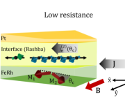 \sidesubfloat[c]
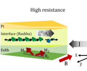 \sidesubfloat[c]
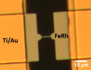 \sidesubfloat[c]
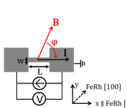
In recent years, a new member of the family of magnetoresistancesnow known as unidirectional magnetoresistance (UMR)has been identified in various ferromagnetic heterostructures having structural inversion asymmetry [26, 27, 28, 29, 30, 31, 32, 33, 34, 35]. As opposed to the aforementioned linear-response magnetoresistances, which are current-independent, the UMR is linearly proportional to the applied current, and changes sign when either the direction of the current or the in-plane magnetization (which needs to be aligned perpendicularly to the current) is reversed. The analogous effect in antiferromagnetic layered structures, however, has not been explored. It is of particular interest to discover a mechanism that generates this effect in antiferromagnetic metals, given the absence of intrinsic spin-dependent scattering [36]a key ingredient in creating the UMR effect in conducting ferromagnets [27, 37].
In this work, we examine the nonlinear magnetotransport in a FeRhPt bilayer system. It is known that FeRh is a magnetic metal, which undergoes a meta-magnetic transition near room temperature from a ferromagnetic to an antiferromagnetic phase [kouvel1962anomalous, thiele2003ferh, cherifi2014electric, 17, lee2015large, chirkova2016giant, 38, chen2017tunneling, 39]. When an in-plane magnetic field is applied perpendicularly to the current direction, a UMR is observed in the antiferromagnetic phase, which changes sign when one switches either the current or the magnetic field orientation. Furthermore, the UMR evolves non-linearly with the external magnetic field and undergoes a sign change as the magnetic field is increased, in stark contrast to the behaviour typically observed in nonmagnetic [40, 41, 42, 43, 44] and ferromagnetic [26, 29, 34, 30, 31, 32, 33, 35] materials. We attribute the UMR effect to the combined actions of the Rashba SOC at the FeRhPt interface and the antiferromagnetic spin canting, as illustrated in Figs. 1 and 1. In what follows, we first present our main experimental results and then compare them to theoretical calculations of the UMR effect based on a tight-binding model Hamiltonian that encapsulates both interfacial Rashba SOC and the spin canting effect, demonstrating excellent agreement between theory and experiment.
II Sample layout and transport measurement
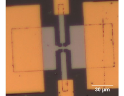
We perform magnetotransport measurements on a FeRh (15 nm)Pt (5 nm) bilayer, where the FeRh current path is oriented along the [110] direction, using lithographically defined microwires (length µm, width µm), as shown in Figs. 1 and 1.
We apply a DC charge current and measure the longitudinal resistances with an additional small AC charge current of 10 µA from a lock-in amplifier, under the application of an external magnetic field . The direction of the field is determined by its azimuthal angle as shown in Fig. 1. We can assume that the Néel order in the FeRh is aligned perpendicular to the in-plane magnetic field and smoothly rotates with it, as a result of having antiferromagnetic domains large enough to be able to define a single antiferromagnetic spin axis on average [17] and a small in-plane anisotropy which corresponds to an effective field of less than 1 T [45, 39]. We note that this method allows for the UMR to be extracted with the first harmonic output of the lock-in amplifier, and that without a DC current bias, the UMR must be measured using the second harmonic output of the lock-in [41]. As shown in Fig. 2, a resistance which is odd under the current polarity, defined as , manifests in the first harmonic measurement on top of the linear-response magnetoresistance background (see Supplementary Section S2). This odd resistance only appears for A/.
[] \sidesubfloat[]
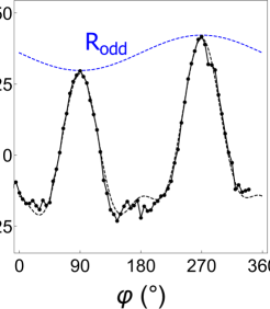 \sidesubfloat[]
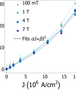 \sidesubfloat[]
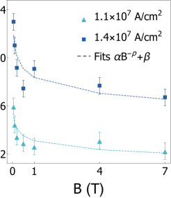
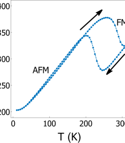
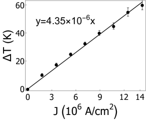
All the measurements are carried out at the base temperature of either 10 K (antiferromagnetic phase) or 310 K (ferromagnetic phase) (Fig. 2). Base temperature refers to the ambient temperature in the sample space. The increase in the device temperature due to Joule heating from the applied current is estimated to be about 4.35 K for A/, by comparing the longitudinal resistance value under finite current density with the corresponding temperature value in Fig. 2. Even with the Joule heating present at a base temperature of 10 K, our device remains strictly within the antiferromagnetic phase (see Supplementary Section S1).
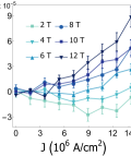
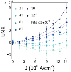
In Figs. 2 and 2, we show the dependence of in the ferromagnetic phase on the applied current and magnetic field, and observe a monotonic increase with respect to the applied current. in the ferromagnetic phase can be fitted with the curve (Fig. 2), which includes the contributions from spin-dependent and magnon scattering mechanisms, in agreement with previous reports on UMR generated in ferromagnetic-metalnormal-metal bilayers [34]. Furthermore, we observe a suppression in for fields above 1 T, scaling with the power law (Fig. 2). This amplitude suppression is also consistent with previous studies of UMR in ferromagnetic-metalnormal-metal bilayers [34], where the UMR originates from the field-induced gap in the magnon excitation spectrum, which reduces the electron-magnon scattering at high fields.
III Observation of UMR in an antiferromagnet
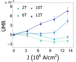
The behavior of the UMR in the antiferromagnetic phase is shown in Figs. 3 and 3. In order to extract the UMR from in the antiferromagnetic phase, we analyzed the contribution from the thermal gradient and related thermoelectric effects. The anomalous Nernst effect and spin Seebeck effect, both producing a longitudinal voltage proportional to (where is the net magnetization and ), can give rise to the same angular dependence as observed for the UMR when [46, 47, 26]. Here, by measuring the transverse (Hall) counterpart scaled by the geometric factor in a similar FeRhPt microwire device, we find that even the maximum thermoelectric voltage contribution in the antiferromagnetic phase is less than 30% (see Supplementary Section S3). We also find that , the amplitude of , has no dependence on current or external field strength in a control sample of FeRh (20 nm) without Pt (see Supplementary Section S3), which indicates a negligible anomalous Nernst effect contribution, in agreement with the literature. We conclude that there is an additional magnetoresistance effect in the FeRhPt bilayers other than thermoelectric voltages. For the antiferromagnetic phase of the FeRhPt bilayer, we extract the UMR from the amplitude of the measured sinusoidal signal (shown in Fig. 2) using UMR, following the convention for ferromagnetic-metalnormal-metal bilayers, in which the UMR of the bilayer increases when the direction of the majority spins in the ferromagnet and the spin accumulation vector are parallel to each other, and decreases when they are antiparallel [26].
[] \sidesubfloat[]
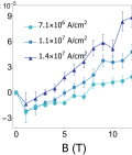 \sidesubfloat[]
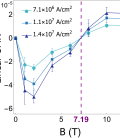 \sidesubfloat[]
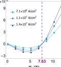
In the antiferromagnetic phase of the FeRhPt bilayer (Figs. 3, 3), we observe a different trend from what was observed in the ferromagnetic phase. In the antiferromagnetic phase, the UMR is not strongly suppressed for fields higher than 1 T. This can be attributed to the lack of magnon-dependent scattering in antiferromagnets [36]. Thus, the antiferromagnetic UMR increases approximately linearly with field and current, for large field and current values. The most striking feature of the UMR in the antiferromagnetic phase is the sign change from negative to positive UMR as the magnetic field is increased, which, to our knowledge, has not been observed in either ferromagnetic or nonmagnetic systems.
The UMR observed in the antiferromagnetic phase cannot be due to the spin Hall effect, since the scattering in a metallic antiferromagnet is independent of the spin polarization [36] and even the canted spin configuration under the external field is not large enough to induce the necessary spin-dependent scattering for a significant spin-Hall UMR (see Supplementary Section S7). Moreover, the observed UMR is isotropic with respect to the direction of the current flow in the crystalline plane (see Supplementary Section S4). Thus, it is unlikely that the UMR in the antiferromagnetic phase originates from strong crystal field effects. A lack of field and current dependence of in the control sample of FeRh (20 nm) without a Pt layer (see Supplementary Section S3) also implies that the observed UMR cannot be attributed to the intrinsic properties of FeRh.
As shall be discussed in the next section, we attribute the UMR in FeRhPt to the combined effects of the Rashba SOC at the interface of FeRh and Pt, and the spin canting in the antiferromagnetic spin sublattices. A calculated UMR based on this theory, which is linear in the applied current, is shown in Fig. 3; this can be compared to the linear component of the experimental UMR (i.e., to first order in the applied current) shown in Fig. 3. As can be seen, in the intermediate magnetic field rangewhere the UMR sign reversal occursthere is excellent qualitative and quantitative agreement between theory and experiment. In the low field limit, however, there is some quantitative disagreement. This is most likely attributable to the effect of thermal magnons, which was not considered in the theoretical model. As an additional scattering source of conduction electrons, the thermal magnons may modify the magnetoresistance at low magnetic fields, but their contribution is expected to diminish as the external field is increaseda trend which is nicely captured by comparing Figs. 3 and 3.
IV Physical origin of UMR
To obtain physical insight into the observed UMR effect arising from the FeRhPt interface, we theoretically investigate the nonlinear magnetotransport by restricting ourselves to the interfacial layer of the FeRh adjacent to the Pt layer, which may be described by the following two-dimensional tight-binding Hamiltonian with broken inversion symmetry of a collinear antiferromagnetic metal with Rashba SOC [48, 2]
| (1) |
where is the on-site energy, is the s-d exchange constant between the local moments and the electron, is the Rashba SOC constant, and and are Pauli matrices which signify the sublattice and spin degrees of freedom, respectively. The nearest-neighbor hopping is represented by , where is the hopping term and the lattice constant.
[] \sidesubfloat[]
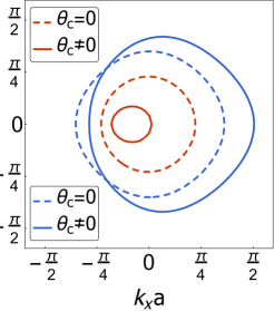 \sidesubfloat[]
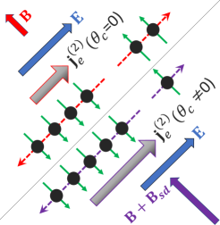 \sidesubfloat[]
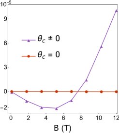
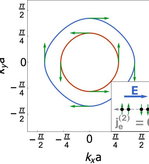
In the absence of an external magnetic field, the Rashba splitting leads to two Fermi contours with opposite spin chirality in equilibrium, as shown in Fig. 4. By applying an in-plane electric field , a pure nonlinear spin current (with no corresponding charge current) can be induced in the system due to spin-momentum locking as well as the symmetric electron distribution in momentum space in the second order of the field [51, 44, 52]. The nonlinear spin current is converted to a nonlinear charge current in the presence of an in-plane magnetic field perpendicular to the current direction (which establishes an imbalance between the two electron fluxes with opposite spin orientations, see dashed bands in Fig. 4), leading to the UMR effect [44, 52].
The Hamiltonian, Eq. (1), is modified by spin canting when an external magnetic field is applied perpendicular to the Néel vector. More specifically, the sublattice magnetizations tilt toward the applied field by an angle relative to the Néel vector, resulting in a net magnetization along the field direction. The canting angle can be determined by minimizing the magnetic energy density of a collinear antiferromagnet as given below
| (2) |
Here, and are the magnetizations of sublattices A and B, is the effective exchange field measuring the interaction between the two sublattices and is the saturation magnetization, where we take . For an external magnetic field applied along the -direction, we find (see Supplementary Section S5). To capture the spin canting effect, we make the substitution for the s-d exchange term in the Hamiltonian. Note that the net magnetization that is parallel to now couples with the same sign to the electronic spin, giving rise to an effective magnetic field .
This strong effective magnetic field due to spin canting greatly enhances the amount of distortion of the Fermi contours when an external magnetic field is applied, as shown by the solid bands in Fig. 4, which leads to a more profound UMR, as shown schematically in Fig. 4. To confirm this, we calculate the nonlinear longitudinal charge current density using the Boltzmann transport formalism (see Supplementary Section S5), where is the band-index, is the momentum relaxation time, and is the group velocity of the -th band. From the total longitudinal resistivity , we calculate the UMR as , with and the Drude conductivity. The calculated UMR, both with and without canting, as a function of the applied magnetic field is plotted in Fig. 4, from which it is evident that spin canting indeed plays an important role in the enhancement of the UMR effect.
V Mechanism of UMR sign change
In order to understand the origin of the sign change in the UMR as the magnetic field intensity is tuned, we first note that this is made possible by spin canting. More precisely, in the presence of canting, the Hamiltonian acquires a significant nonlinear dependence on the magnetic field through the effective field , which, in turn, allows for the UMR to evolve nonlinearly with respect to . Another element that plays an important role is the asymmetry of the band structure as the magnetic field and, by extension, , are switched on.
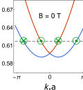
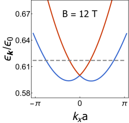
Initially, at zero magnetic field, as depicted in Fig. 5, the conduction bands are symmetric about the point and the UMR is absent. When the magnetic field is turned on, a small spin-dependent asymmetry develops in the band structure, which results in a positive UMR contribution from the outer band (blue in Fig. 5) and a negative contribution from the inner band (red). As shown in Figs. 5 and 5, at low fields such as 3 T, the asymmetry in the outer band is not enough to counter the dominant presence of the inner band near the Fermi level and the overall UMR is negative.
As the magnetic field strength is increased, the inner band continues its ascent from the Fermi sea, while the asymmetry of the outer band near the Fermi level continues to grow. At around 7-8 T, the contribution of the two bands becomes equal, at which point the overall UMR undergoes a sign change. As depicted in Fig. 5, at large fields, the contribution from the outer band is dominant near the Fermi level and the UMR is positive. The dependence of the UMR for each conduction band on the magnetic field for a given current value is displayed in Fig. 5, along with the theoretically predicted field value of 7.63 T at which the sign change occurs. This value may be compared with the sign-change field of the linear components of the observed UMR (Fig. 3). The observed magnetic field value of T is in very good agreement with the theoretically predicted field value.
[] \sidesubfloat[]
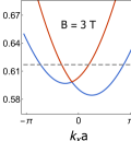 \sidesubfloat[]
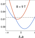 \sidesubfloat[]
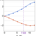
Based on this picture, it is also possible to understand why such a magnetic-field-dependent sign change in the UMR is unique to antiferromagnetic systems and is not expected to occur in ferromagnetic and nonmagnetic systems. In the latter, one could still have a positive or negative UMR depending on the relative position of the Fermi level with respect to the conduction bands; However, the UMR would not change sign in these systems due to the lack of sublattice degree of freedom and the resulting antiferromagnetic spin canting (see Supplementary Section S6).
VI Conclusion
In summary, we observe a UMR in the antiferromagnetic phase of a FeRhPt bilayer, which undergoes a sign change and then increases strongly with an increasing external magnetic field, largely different from UMRs in ferromagnetic and nonmagnetic systems. We show that the Rashba SOC alone, a mechanism known for UMRs in ferromagnetic and nonmagnetic systems, cannot explain the sizable UMR in the antiferromagnetic bilayer. Antiferromagnetic spin canting also plays a crucial role in enhancing the UMR by inducing a strong effective magnetic field that significantly distorts the band structure.
The UMR effect we have observed is not exclusive to FeRhPt bilayers and is expected to exist in antiferromagnetic heterostructures satisfying two conditions: an easy-plane antiferromagnet which displays magnetic domains large enough to define a single antiferromagnetic spin axis on average, and small in-plane anisotropy to ensure coherent rotation of the spin axis with an applied in-plane field. Thus, in the context of antiferromagnetism, this effect has both fundamental and practical implications. First, the new mechanism for UMR in the antiferromagnetic bilayer can advance fundamental understanding of non-collinear antiferromagnetic systems. Antiferromagnets have recently attracted great interest as systems that host emergent phenomena, competing orders, and symmetry-tunable band-structures. Therefore, our findings can motivate future studies to further explore the interplay between spin texture, electronic band structure, and the associated emergent phenomena in antiferromagnets.
Moreover, key parameters of antiferromagnets (difficult to measure in thin films) can be back-engineered from the UMR effect. For example, susceptibility and magnetocrystalline anisotropy parameters have not been directily measured in FeRh thin films [39]. Based on the field-dependence of the UMR that we report, we can estimate the magnetic susceptibility of the 15 nm thick FeRh thin films to be five times greater than what has been reported for bulk samples (see Supplementary Section S5). In addition, our analysis reveals that while the value of the UMR sign reversal field is, in general, a complicated function of the materials parameters of the bilayer system, we expect that it will scale linearly with the magnetic susceptibility (see Supplementary Section S9)a prediction which may prove useful in future studies of UMR in other antiferromagnetic systems. From the perspective of applications, our findings may also lead toward the development of antiferromagnet-based spintronics, such as two-terminal devices [53, 54], where the spin information can be controlled by both electric voltage and magnetic field.
Acknowledgements
We thank David G. Cahill and Matthew J. Gilbert for valuable discussions. This research was primarily supported by the NSF through the University of Illinois at Urbana-Champaign Materials Research Science and Engineering Center DMR-1720633 and was carried out in part in the Materials Research Laboratory Central Research Facilities, University of Illinois. Thin-film growth at Argonne National Laboratory was supported by the U.S. Department of Energy, Office of Science, Materials Science and Engineering Division. J. O. acknowledges support from the Army under W911NF-20-1-0024. Work by M. M. and S. S.-L. Z. was supported by the College of Arts and Sciences, Case Western Reserve University.
Author Contributions
S. S., J. S. and N. M. designed the magnetotransport experiments. J. G., H. S. and A. H. were responsible for synthesizing FeRh films. S. S. and J. S. performed magnetic characterization of FeRh. S. S., J. S., J. O., J. G. and H. S. fabricated devices. S. S., J. S. and J. O. performed magnetotransport experiments. A. H. and N. M. supervised the experimental work. M. M. and S. S.-L. Z. devised the theory. S. S. and M. M. analyzed the results with J. S., S. S.-L. Z., and N. M. providing input. S. S., M. M., J. S., S. S.-L. Z., and N. M. wrote the manuscript with input from all other authors.
Materials and Methods
The FeRh films used in this work were deposited onto (100) MgO substrates using DC magnetron sputtering. Before sputtering, the substrates were annealed within the sputter deposition system at 850∘ C for one hour in order to desorb the potential contaminants on the surface. After the substrates were cleaned, the temperature was lowered to 450∘ C for deposition. The sputter target used for deposition was an equiatomic FeRh source. During growth, 6.5 sccm of Ar gas was introduced into the chamber, and the pressure was set to 6 mTorr. The DC sputtering power used was 50 W, and the growth rate was 0.7 /s. After one hour post-annealing of FeRh films at 650∘ C, the heater was turned off and the films were cooled down to room temperature before depositing the Pt layer, which was deposited at room temperature, with the pressure of 5 mTorr, power of 7 W, and the growth rate of 0.6 /s [55]. The films were subsequently patterned into microwires by direct writing laser lithography and Ar milling. The microwires were patterned so that the current flowed along the [110] crystalline orientations of FeRh.
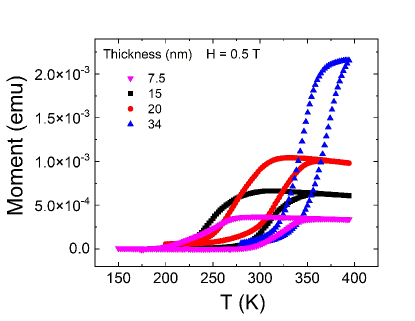
For thin FeRh films deposited onto MgO substrates, it has been reported that there exist residual ferromagnetic moments, confined to within 6-8 nm of the interface of FeRh and MgO [56]. To determine the magnitude of the residual ferromagnetic moment, magnetic characterization on FeRh (15 nm) with an in-plane field was carried out in a vibrating sample magnetometer by Quantum Design. With an in-plane field of 0.5 T, the residual ferromagnetic moment at K was estimated to be 4 % of the saturated magnetization in the ferromagnetic phase (1260 emu/) (see Supplementary Section S10). The residual ferromagnetic moment, however, does not affect the UMR because no UMR is observed for the single layer FeRh thin film on MgO (see Supplementary Section S3) and the field scale for the observed antiferromagnetic UMR is very large compared to the ferromagnetic case (see Figures 2 and 3). Transport experiments were four-probe resistance measurements carried out using the Physical Property Measurement System by Quantum Design equipped with a horizontal rotator module. A DC current of the order of mA, generated by a Keithley sourcemeter 2400, was applied to achieve the desired current density and a 13 Hz AC current of 10 µA, generated by a Stanford Research Systems SR830 lock-in amplifier, was applied to probe the magnetoresistance. To accommodate different device sizes, the current was adapted to have the same current density. The rotation of the sample was provided by a motorized stage with a precision of 0.0133°.
References
- Jungwirth et al. [2016] T. Jungwirth, X. Marti, P. Wadley, and J. Wunderlich, Antiferromagnetic Spintronics, Nat. Nanotechnol. 11, 231 (2016).
- Baltz et al. [2018] V. Baltz, A. Manchon, M. Tsoi, T. Moriyama, T. Ono, and Y. Tserkovnyak, Antiferromagnetic Spintronics, Rev. Mod. Phys. 90, 015005 (2018).
- Siddiqui et al. [2020] S. A. Siddiqui, J. Sklenar, K. Kang, M. J. Gilbert, A. Schleife, N. Mason, and A. Hoffmann, Metallic Antiferromagnets, J. Appl. Phys. 128, 040904 (2020).
- Wadley et al. [2016] P. Wadley, B. Howells, J. Železný, C. Andrews, V. Hills, R. P. Campion, V. Novák, K. Olejník, F. Maccherozzi, S. S. Dhesi, et al., Electrical Switching of an Antiferromagnet, Science 351, 587 (2016).
- Bodnar et al. [2018] S. Y. Bodnar, L. Šmejkal, I. Turek, T. Jungwirth, O. Gomonay, J. Sinova, A. Sapozhnik, H.-J. Elmers, M. Kläui, and M. Jourdan, Writing and Reading Antiferromagnetic by Néel Spin-Orbit Torques and Large Anisotropic Magnetoresistance, Nat. Commun. 9, 1 (2018).
- Wadley et al. [2018] P. Wadley, S. Reimers, M. J. Grzybowski, C. Andrews, M. Wang, J. S. Chauhan, B. L. Gallagher, R. P. Campion, K. W. Edmonds, S. S. Dhesi, et al., Current Polarity-Dependent Manipulation of Antiferromagnetic Domains, Nat. Nanotechnol. 13, 362 (2018).
- Meinert et al. [2018] M. Meinert, D. Graulich, and T. Matalla-Wagner, Electrical Switching of Antiferromagnetic and the Role of Thermal Activation, Phys. Rev. Applied 9, 064040 (2018).
- Zhou et al. [2018] X. F. Zhou, J. Zhang, F. Li, X. Z. Chen, G. Y. Shi, Y. Z. Tan, Y. D. Gu, M. S. Saleem, H. Q. Wu, F. Pan, and C. Song, Strong Orientation-Dependent Spin-Orbit Torque in Thin Films of the Antiferromagnet , Phys. Rev. Applied 9, 054028 (2018).
- DuttaGupta et al. [2020] S. DuttaGupta, A. Kurenkov, O. A. Tretiakov, G. Krishnaswamy, G. Sala, V. Krizakova, F. Maccherozzi, S. Dhesi, P. Gambardella, S. Fukami, et al., Spin-Orbit Torque Switching of an Antiferromagnetic Metallic Heterostructure, Nat. Commun. 11, 1 (2020).
- Suzuki et al. [2016] T. Suzuki, R. Chisnell, A. Devarakonda, Y. T. Liu, W. Feng, D. Xiao, J. W. Lynn, and J. G. Checkelsky, Large Anomalous Hall Effect in a Half-Heusler Antiferromagnet, Nat. Phys. 12, 1119 (2016).
- Takahashi et al. [2018] K. S. Takahashi, H. Ishizuka, T. Murata, Q. Y. Wang, Y. Tokura, N. Nagaosa, and M. Kawasaki, Anomalous Hall Effect Derived from Multiple Weyl Nodes in High-Mobility Films, Sci. Adv. 4 (2018).
- [12] X. Li, A. H. MacDonald, and H. Chen, Quantum Anomalous Hall Effect through Canted Antiferromagnetism, arXiv:1902.10650 [cond-mat.mes-hall] .
- Yang et al. [2020] R. Yang, M. Corasaniti, C. C. Le, Z. Y. Liao, A. F. Wang, Q. Du, C. Petrovic, X. G. Qiu, J. P. Hu, and L. Degiorgi, Spin-Canting-Induced Band Reconstruction in the Dirac Material , Phys. Rev. Lett. 124, 137201 (2020).
- Kipp et al. [2021] J. Kipp, K. Samanta, F. R. Lux, M. Merte, D. Go, J.-P. Hanke, M. Redies, F. Freimuth, S. Blügel, M. Ležaić, and Y. Mokrousov, The Chiral Hall Effect in Canted Ferromagnets and Antiferromagnets, Commun. Phys. 4, 99 (2021).
- Kimel et al. [2004] A. V. Kimel, A. Kirilyuk, A. Tsvetkov, R. V. Pisarev, and T. Rasing, Laser-Induced Ultrafast Spin Reorientation in the Antiferromagnet TmFeO3, Nature 429, 850 (2004).
- Saidl et al. [2017] V. Saidl, P. Němec, P. Wadley, V. Hills, R. P. Campion, V. Novák, K. W. Edmonds, F. Maccherozzi, S. S. Dhesi, B. L. Gallagher, et al., Optical Determination of the Néel Vector in a CuMnAs Thin-Film Antiferromagnet, Nat. Photon. 11, 91 (2017).
- Marti et al. [2014] X. Marti, I. Fina, C. Frontera, J. Liu, P. Wadley, Q. He, R. Paull, J. Clarkson, J. Kudrnovskỳ, I. Turek, et al., Room-Temperature Antiferromagnetic Memory Resistor, Nat. Mater. 13, 367 (2014).
- Moriyama et al. [2018] T. Moriyama, K. Oda, T. Ohkochi, M. Kimata, and T. Ono, Spin Torque Control of Antiferromagnetic Moments in NiO, Sci. Rep. 8, 14167 (2018).
- Baldrati et al. [2018] L. Baldrati, A. Ross, T. Niizeki, C. Schneider, R. Ramos, J. Cramer, O. Gomonay, M. Filianina, T. Savchenko, D. Heinze, et al., Full Angular Dependence of the Spin Hall and Ordinary Magnetoresistance in Epitaxial Antiferromagnetic NiO(001)/Pt Thin Films, Phys. Rev. B 98, 024422 (2018).
- Moriyama et al. [2015] T. Moriyama, N. Matsuzaki, K.-J. Kim, I. Suzuki, T. Taniyama, and T. Ono, Sequential Write-Read Operations in FeRh Antiferromagnetic Memory, Appl. Phys. Lett. 107, 122403 (2015).
- Hoogeboom et al. [2017] G. R. Hoogeboom, A. Aqeel, T. Kuschel, T. T. M. Palstra, and B. J. van Wees, Negative Spin Hall Magnetoresistance of Pt on the Bulk Easy-Plane Antiferromagnet NiO, Appl. Phys. Lett. 111, 052409 (2017).
- Fischer et al. [2018] J. Fischer, O. Gomonay, R. Schlitz, K. Ganzhorn, N. Vlietstra, M. Althammer, H. Huebl, M. Opel, R. Gross, S. T. B. Goennenwein, and S. Geprägs, Spin Hall Magnetoresistance in Antiferromagnet/Heavy-Metal Heterostructures, Phys. Rev. B 97, 014417 (2018).
- Manchon [2017] A. Manchon, Spin Hall Magnetoresistance in Antiferromagnet/Normal Metal Bilayers, Phys. Status Solidi (RRL)–Rapid Research Letters 11, 1600409 (2017).
- McGuire and Potter [1975] T. McGuire and R. Potter, Anisotropic Magnetoresistance in Ferromagnetic 3d Alloys, IEEE Trans. Magn. 11, 1018 (1975).
- Nakayama et al. [2013] H. Nakayama, M. Althammer, Y.-T. Chen, K. Uchida, Y. Kajiwara, D. Kikuchi, T. Ohtani, S. Geprägs, M. Opel, S. Takahashi, et al., Spin Hall Magnetoresistance Induced by a Nonequilibrium Proximity Effect, Phys. Rev. Lett. 110, 206601 (2013).
- Avci et al. [2015] C. O. Avci, K. Garello, A. Ghosh, M. Gabureac, S. F. Alvarado, and P. Gambardella, Unidirectional Spin Hall Magnetoresistance in Ferromagnet/Normal Metal Bilayers, Nat. Phys. 11, 570 (2015).
- Zhang and Vignale [2016] S. S.-L. Zhang and G. Vignale, Theory of Unidirectional Spin Hall Magnetoresistance in Heavy-Metal/Ferromagnetic-Metal Bilayers, Phys. Rev. B 94, 140411 (2016).
- Yasuda et al. [2016] K. Yasuda, A. Tsukazaki, R. Yoshimi, K. S. Takahashi, M. Kawasaki, and Y. Tokura, Large Unidirectional Magnetoresistance in a Magnetic Topological Insulator, Phys. Rev. Lett. 117, 127202 (2016).
- Langenfeld et al. [2016] S. Langenfeld, V. Tshitoyan, Z. Fang, A. Wells, T. Moore, and A. Ferguson, Exchange Magnon Induced Resistance Asymmetry in Permalloy Spin-Hall Oscillators, Appl. Phys. Lett. 108, 192402 (2016).
- Li et al. [2017] T. Li, S. Kim, S.-J. Lee, S.-W. Lee, T. Koyama, D. Chiba, T. Moriyama, K.-J. Lee, K.-J. Kim, and T. Ono, Origin of Threshold Current Density for Asymmetric Magnetoresistance in Pt/Py Bilayers, Appl. Phys. Express 10, 073001 (2017).
- Yin et al. [2017] Y. Yin, D.-S. Han, M. C. de Jong, R. Lavrijsen, R. A. Duine, H. J. Swagten, and B. Koopmans, Thickness Dependence of Unidirectional Spin-Hall Magnetoresistance in Metallic Bilayers, Appl. Phys. Lett. 111, 232405 (2017).
- Olejník et al. [2015] K. Olejník, V. Novák, J. Wunderlich, and T. Jungwirth, Electrical Detection of Magnetization Reversal without Auxiliary Magnets, Phys. Rev. B 91, 180402 (2015).
- Lv et al. [2018] Y. Lv, J. Kally, D. Zhang, J. S. Lee, M. Jamali, N. Samarth, and J.-P. Wang, Unidirectional Spin-Hall and Rashba-Edelstein Magnetoresistance in Topological Insulator-Ferromagnet Layer Heterostructures, Nat. Commun. 9, 111 (2018).
- Avci et al. [2018] C. O. Avci, J. Mendil, G. S. D. Beach, and P. Gambardella, Origins of the Unidirectional Spin Hall Magnetoresistance in Metallic Bilayers, Phys. Rev. Lett. 121, 087207 (2018).
- Guillet et al. [2021] T. Guillet, A. Marty, C. Vergnaud, M. Jamet, C. Zucchetti, G. Isella, Q. Barbedienne, H. Jaffrès, N. Reyren, J. M. George, and A. Fert, Large Rashba Unidirectional Magnetoresistance in the Fe/Ge(111) Interface States, Phys. Rev. B 103, 064411 (2021).
- Núñez et al. [2006] A. S. Núñez, R. A. Duine, P. Haney, and A. H. MacDonald, Theory of Spin Torques and Giant Magnetoresistance in Antiferromagnetic Metals, Phys. Rev. B 73, 214426 (2006).
- Zhang and Vignale [2017] S. S.-L. Zhang and G. Vignale, Theory of Unidirectional Magnetoresistance in Magnetic Heterostructures, Proc. SPIE 10357, 1035707 (2017).
- Barker and Chantrell [2015] J. Barker and R. W. Chantrell, Higher-Order Exchange Interactions Leading to Metamagnetism in FeRh, Phys. Rev. B 92, 094402 (2015).
- McGrath et al. [2020] B. R. McGrath, R. E. Camley, and K. L. Livesey, Self-Consistent Local Mean-Field theory for Phase Transitions and Magnetic Properties of FeRh, Phys. Rev. B 101, 014444 (2020).
- Ideue et al. [2017] T. Ideue, K. Hamamoto, S. Koshikawa, M. Ezawa, S. Shimizu, Y. Kaneko, Y. Tokura, N. Nagaosa, and Y. Iwasa, Bulk Rectification Effect in a Polar Semiconductor, Nat. Phys. 13, 578 (2017).
- Guillet et al. [2020] T. Guillet, C. Zucchetti, Q. Barbedienne, A. Marty, G. Isella, L. Cagnon, C. Vergnaud, H. Jaffrès, N. Reyren, J.-M. George, et al., Observation of Large Unidirectional Rashba Magnetoresistance in Ge(111), Phys. Rev. Lett. 124, 027201 (2020).
- Fan et al. [2019] Y. Fan, Q. Shao, L. Pan, X. Che, Q. He, G. Yin, C. Zheng, G. Yu, T. Nie, M. R. Masir, et al., Unidirectional Magneto-Resistance in Modulation-Doped Magnetic Topological Insulators, Nano Lett. 19, 692 (2019).
- He et al. [2018a] P. He, S. M. Walker, S. S.-L. Zhang, F. Y. Bruno, M. S. Bahramy, J. M. Lee, R. Ramaswamy, K. Cai, O. Heinonen, G. Vignale, et al., Observation of Out-of-Plane Spin Texture in a Two-Dimensional Electron Gas, Phys. Rev. Lett. 120, 266802 (2018a).
- He et al. [2018b] P. He, S. S.-L. Zhang, D. Zhu, Y. Liu, Y. Wang, J. Yu, G. Vignale, and H. Yang, Bilinear Magnetoelectric Resistance as a Probe of Three-Dimensional Spin Texture in Topological Surface States, Nat. Phys. 14, 495 (2018b).
- Mancini et al. [2013] E. Mancini, F. Pressacco, M. Haertinger, E. Fullerton, T. Suzuki, G. Woltersdorf, and C. Back, Magnetic Phase Transition in Iron–Rhodium Thin Films Probed by Ferromagnetic Resonance, J. Phys. D: Appl. Phys. 46, 245302 (2013).
- Weiler et al. [2012] M. Weiler, M. Althammer, F. D. Czeschka, H. Huebl, M. S. Wagner, M. Opel, I.-M. Imort, G. Reiss, A. Thomas, R. Gross, and S. T. B. Goennenwein, Local Charge and Spin Currents in Magnetothermal Landscapes, Phys. Rev. Lett. 108, 106602 (2012).
- Kikkawa et al. [2013] T. Kikkawa, K. Uchida, Y. Shiomi, Z. Qiu, D. Hou, D. Tian, H. Nakayama, X.-F. Jin, and E. Saitoh, Longitudinal Spin Seebeck Effect Free from the Proximity Nernst Effect, Phys. Rev. Lett. 110, 067207 (2013).
- Železný et al. [2014] J. Železný, H. Gao, K. Výborný, J. Zemen, J. Mašek, A. Manchon, J. Wunderlich, J. Sinova, and T. Jungwirth, Relativistic Néel-Order Fields Induced by Electrical Current in Antiferromagnets, Phys. Rev. Lett. 113, 157201 (2014).
- Saidaoui et al. [2017] H. B. M. Saidaoui, X. Waintal, and A. Manchon, Robust Spin Transfer Torque in Antiferromagnetic Tunnel Junctions, Phys. Rev. B 95, 134424 (2017).
- Haney et al. [2013] P. M. Haney, H.-W. Lee, K.-J. Lee, A. Manchon, and M. D. Stiles, Current Induced Torques and Interfacial Spin-Orbit Coupling: Semiclassical Modeling, Phys. Rev. B 87, 174411 (2013).
- Hamamoto et al. [2017] K. Hamamoto, M. Ezawa, K. W. Kim, T. Morimoto, and N. Nagaosa, Nonlinear Spin Current Generation in Noncentrosymmetric Spin-Orbit Coupled Systems, Phys. Rev. B 95, 224430 (2017).
- He et al. [2019] P. He, S. S.-L. Zhang, D. Zhu, S. Shi, O. G. Heinonen, G. Vignale, and H. Yang, Nonlinear Planar Hall Effect, Phys. Rev. Lett. 123, 016801 (2019).
- Miron et al. [2011] I. M. Miron, K. Garello, G. Gaudin, P.-J. Zermatten, M. V. Costache, S. Auffret, S. Bandiera, B. Rodmacq, A. Schuhl, and P. Gambardella, Perpendicular Switching of a Single Ferromagnetic Layer Induced by In-Plane Current Injection, Nature 476, 189 (2011).
- Liu et al. [2012] L. Liu, C.-F. Pai, Y. Li, H. Tseng, D. Ralph, and R. Buhrman, Spin-Torque Switching with the Giant Spin Hall Effect of Tantalum, Science 336, 555 (2012).
- Saglam [2019] H. Saglam, Spin Transport and Spin-Orbit Torques in Antiferromagnets, Ph.D. thesis, Illinois Institute of Technology (2019).
- Fan et al. [2010] R. Fan, C. J. Kinane, T. R. Charlton, R. Dorner, M. Ali, M. A. de Vries, R. M. D. Brydson, C. H. Marrows, B. J. Hickey, D. A. Arena, et al., Ferromagnetism at the Interfaces of Antiferromagnetic FeRh Epilayers, Phys. Rev. B 82, 184418 (2010).
- Moriyama et al. [2018] T. Moriyama, W. Zhou, T. Seki, K. Takanashi, and T. Ono, Spin-Orbit-Torque Memory Operation of Synthetic Antiferromagnets, Phys. Rev. Lett. 121, 167202 (2018).
- Saglam et al. [2020] H. Saglam, C. Liu, Y. Li, J. Sklenar, J. Gibbons, D. Hong, V. Karakas, J. E. Pearson, O. Ozatay, W. Zhang, et al., Anomalous Hall and Nernst Effects in FeRh (2020), arXiv:2012.14383 [cond-mat.mtrl-sci] .
- Wu et al. [2016] S. M. Wu, W. Zhang, A. KC, P. Borisov, J. E. Pearson, J. S. Jiang, D. Lederman, A. Hoffmann, and A. Bhattacharya, Antiferromagnetic Spin Seebeck Effect, Phys. Rev. Lett. 116, 097204 (2016).
- Shiomi et al. [2017] Y. Shiomi, R. Takashima, D. Okuyama, G. Gitgeatpong, P. Piyawongwatthana, K. Matan, T. J. Sato, and E. Saitoh, Spin Seebeck Effect in the Polar Antiferromagnet , Phys. Rev. B 96, 180414 (2017).
- Li et al. [2019] J. Li, Z. Shi, V. H. Ortiz, M. Aldosary, C. Chen, V. Aji, P. Wei, and J. Shi, Spin Seebeck Effect from Antiferromagnetic Magnons and Critical Spin Fluctuations in Epitaxial Films, Phys. Rev. Lett. 122, 217204 (2019).
- Touloukian et al. [1971] Y. S. Touloukian, R. W. Powell, C. Y. Ho, and P. G. Klemens, Thermophysical Properties of Matter, New York 2, 158 (1971).
- Swartz and Pohl [1987] E. Swartz and R. Pohl, Thermal Resistance at Interfaces, Appl. Phys. Lett. 51, 2200 (1987).
- Duy Khang and Hai [2019] N. H. Duy Khang and P. N. Hai, Giant Unidirectional Spin Hall Magnetoresistance in Topological Insulator–Ferromagnetic Semiconductor Heterostructures, J. Appl. Phys. 126, 233903 (2019).
- Navarro et al. [1999] E. Navarro, A. Hernando, A. Yavari, D. Fiorani, and M. Rosenberg, Grain-Boundary Magnetic Properties of Ball-Milled Nanocrystalline FexRh100-x Alloys, J. Appl. Phys. 86, 2166 (1999).
- Barton et al. [2017] C. Barton, T. Ostler, D. Huskisson, C. Kinane, S. Haigh, G. Hrkac, and T. Thomson, Substrate Induced Strain Field in FeRh Epilayers Grown on Single Crystal MgO (001) Substrates, Sci. Rep. 7, 1 (2017).
- Li et al. [2021] Z. Li, J. Zhao, Q. Zhu, X. Lv, C. Cao, X. Zhu, L. Sun, Y. Peng, W. Cheng, D. Jiang, et al., Electric Control of Magnetic Properties in Epitaxially Grown FeRh/MgO/PMN-PT Heterostructures, J. Alloys Compd. 868, 159220 (2021).
- Arregi et al. [2020] J. A. Arregi, O. Caha, and V. Uhlíř, Evolution of Strain Across the Magnetostructural Phase Transition in Epitaxial FeRh Films on Different Substrates, Phys. Rev. B 101, 174413 (2020).
- Qiao et al. [2022] K. Qiao, Y. Liang, H. Zhang, F. Hu, Z. Yu, Y. Long, J. Wang, J. Sun, T. Zhao, and B. Shen, Manipulation of Magnetocaloric Effect in FeRh Films by Epitaxial Growth, J. Alloys Compd. 907, 164574 (2022).
Supplemental Material for “Unidirectional magnetoresistance in antiferromagnetheavy-metal bilayers”
S1 Joule heating in the microwire device
While the ambient temperature in the sample space is kept at 10 K for all measurements in the antiferromagnetic phase, the true device temperature can increase due to Joule heating from the applied current. The temperature increase from Joule heating is estimated by comparing the longitudinal resistance for finite current density at T with the corresponding longitudinal resistance measured without the applied DC current (e.g., as shown in Fig. 2a). As shown in Fig. S.1, the temperature increase per A/ is estimated to be about 4.35 K, corresponding to K for the maximum applied current density of A/. While the temperature sweep of the resistance shows that the device is strictly antiferromagnetic until K (Fig. 2a), we further confirm this by measuring anisotropic magnetoresistance (AMR) at T, with no applied DC current, for temperatures ranging from K to K (Fig. S.2). Given that there is a 90° phase difference in the AMR signal between ferromagnets and antiferromagnets [57], no phase shift in the AMR up to K confirms that the device is indeed antiferromagnetic even with the maximum current density applied.
S2 Linear-response magnetoresistance in FeRhPt bilayer
When we measure how the longitudinal resistance changes with respect to the orientation of the current from the external magnetic field, the raw data can be decomposed into two components: linear-response magnetoresistance (MR) which is current-independent and even under the current reversal, and resistance which is odd under the current polarity, (Fig. S.2). In the FeRhPt bilayer, we observe how the linear-response MR depends on the temperature (Fig. S.2), the applied magnetic field (Fig. S.2), and the FeRh crystal orientation (Fig. S.2). is negligible for current densities lower than A/ so we assume that AMR with no applied DC current can represent the linear-response MR.
[] \sidesubfloat[]
 \sidesubfloat[]
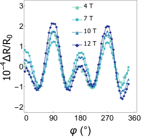 \sidesubfloat[]
Throughout the whole temperature and field range for both FeRh crystal orientations, the linear-response MR is much larger in magnitude compared to the UMR and has a non-trivial angular dependence consisting of two-fold and four-fold contributions, where the relative magnitudes of the two contributions vary with the temperature and external field strength. For instance, for the temperature dependence of AMR in the FeRh[110]Pt device at T, the two-fold MR contribution is dominant at K compared to the four-fold contribution, whereas the two-fold and four-fold contributions are comparable at K (Fig. S.2). Similarly, for the field dependence of the AMR in the FeRh[110]Pt device at K, the two-fold MR contribution is dominant at T compared to the four-fold contribution, whereas the two-fold and four-fold contributions are comparable at T (Fig. S.2).
We also note that the linear-response MR is dramatically different when the current is along the [100] direction of FeRh compared to the [110] direction (Figs. S.2, S.2). This is greatly in contrast to the UMR in FeRhPt, which is independent of whether the current is aligned along the [100]or [110]direction of FeRh (see Supplementary Section S4).
The potential origins of this complex linear-response MR include AMR from the FeRh layer and spin Hall magnetoresistance (SMR) due to the Pt layer. And given the strong interfacial effect, other linear-response MRs associated with the interface could also be present. To separate out AMR, SMR, and other linear-response MRs from the interface, more measurements and samples would be necessary. An example of a control study would be inserting a spacer layer such as Cu between the FeRh and the Pt to help determine if the linear-response MR in FeRhPt arises from the SMR.
We also note that separating out linear-response MR effects (between AMR and SMR for instance) is non-trivial. Ideally, one would need to vary the thickness of the FeRh layer in such a study. This presents problems because antiferromagnetic properties are sensitive to the thickness in thin films. In particular, the antiferromagnetic ordering rapidly weakens as the thickness decreases. This may be in part due to the presence of residual ferromagnetic moments near the MgOFeRh interface [56]. It is expected then that other quantities, such as the magnetic susceptibility, will change. This makes a comparative study involving field-dependent data in different samples challenging.
Importantly, the linear-response MR effect strongly depends on the orientation of the current with respect to crystalline direction of the FeRh film, which greatly contrasts with the UMR in FeRhPt. Thus, while the origin of the linear-response MR in FeRhPt requires much more detailed analysis, we believe that it is beyond the scope of this study, and does not impact our main conclusions.
S3 Separating the thermal contribution in
Thermoelectric effects must be carefully considered in the measurement of electrical signals due to inevitable Joule heating and consequent temperature gradients in the sample. Only signals originating from the anomalous Nernst effect and the longitudinal spin Seebeck effect under the vertical thermal gradient possess the same symmetry as that of the UMR [26].
In order to determine the resistance contribution from the anomalous Nernst effect in the FeRhPt bilayer, we conduct a control measurement with an uncapped FeRh (20 nm) microwire device. Given similar resistivities between FeRh and Pt (µ at K, µ), we expect a similar thermal profile between 20 nm of uncapped FeRh and a FeRh (15 nm)Pt (5 nm) bilayer under the same current density. Thus, the behavior of in the uncapped FeRh device, which only includes the resistance contribution from the anomalous Nernst effect, should reflect the significance of the resistance contribution from the anomalous Nernst effect in the FeRhPt bilayer device.
Figs. S.3 and S.3 show the negligible evolution in with respect to the applied current and applied field in an uncapped FeRh sample, implying that the anomalous Nernst effect contribution in the uncapped FeRh sample is negligible. Although an anomalous Nernst effect has been previously observed in the antiferromagnetic phase of FeRh [58], we find the contribution in our experiments to be negligible, particularly compared to the Rashba-induced UMR signal.
[] \sidesubfloat[]
In the following, we discuss how the spin Seebeck effect can be separated from the Rashba-induced UMR in the bilayer FeRhPt sample.
Since the magnetoresistance and the thermal signal have the same microscopic origin, their amplitude is proportional to the physical distance over which they are measured. Thus, by measuring the thermal signal in the transverse geometry, one can accurately determine its sign and magnitude in the longitudinal measurements. Similar to ferromagnetnormal-metal bilayers [26], we must consider the fact that the transverse thermoelectric signal is mixed with the transverse spin-orbit torque signal. These two effects, however, can be separated quantitatively using different angular symmetry and field dependence. In the in-plane angular sweep of the applied field, the field-like spin-orbit torque (FL-SOT) gives a contribution to the Hall signal proportional to , whereas the anti-damping-like spin-orbit torque (AD-SOT) and the thermal effect both give a contribution proportional to [26]. The AD-SOT and thermal contributions can be further separated by considering that the AD-SOT induces dynamical oscillations of the magnetization, the amplitude of which is proportional to the magnetic susceptibility of the antiferromagnetic layer. The resulting Hall spin-orbit torque signal therefore depends on the susceptibility of the antiferromagnetic layer, which is expected to be independent of the external field strength, whereas the thermal contribution, for instance, that of the spin Seebeck effect, increases linearly with the applied field [59, 60, 61], as expected for the smoothly canting sublattice magnetizations in the antiferromagnetic layer.
In order to estimate the thermal contribution in , we fabricated a FeRh (15 nm)Pt (5 nm) control device along the [110] direction of FeRh, with a geometry of a microwire combined with a transverse channel (Fig. S.4).
While the width of the control device is 3 µm, twice as that of the main device, the same current density was applied to achieve a similar thermal profile across the device. There can be two contributions to the temperature gradient: bulk thermal conductance where and interfacial thermal conductance G where ( is the sheet resistance, is the power, and are the length and width of the microwire). Since for MgO [62] and for the interface Rh:Fe [63] (similar to the interface of FeRhMgO), for µm and thus we can conclude that the heating due to the interfacial thermal conductance effect at the low temperature of K is orders of magnitude more dominant than the heating due to the bulk thermal conductance effect for microwires. We note that is independent of the width of the microwire.
Using the Hall signal in the control FeRhPt microwire device at current density A/, the resistance contribution having dependence which represents the combined AD-SOT contribution and thermal effectwas separated from the signal having dependence. Then, a linear fitting on the was done to extract the thermal contribution, represented as the slope in Fig. S.4. This extracted thermal contribution was then multiplied by the aspect ratio of the device to estimate the thermal contribution along the longitudinal direction, . Lastly, given that [64], the longitudinal thermal contribution per unit field and unit current density was calculated.
[] \sidesubfloat[]
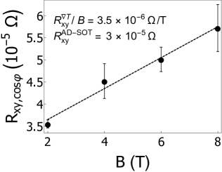
The estimated longitudinal thermal contribution per unit field and unit current density is /(T), which corresponds to only 27% of at maximum. The longitudinal spin Seebeck effect in antiferromagnets has been previously reported to be lowering resistance for and increasing resistance for [59, 60, 61]. Thus, we propose that for the antiferromagnetic FeRhPt bilayer also follows the same trend and we calculate a true UMR contribution using UMR, which shows a similar qualitative behavior as . In addition, we note that the thermal contribution does not change its sign over field or current density, suggesting that thermal contributions cannot explain the UMR sign change observed in the antiferromagnetic phase (Fig. 3).
S4 Dependence of UMR on the current orientation with respect to crystalline axes
We investigated the crystal orientation dependence of the UMR. A microwire identical to the one discussed in the main text was defined along the [100] direction of FeRh using the same fabrication process. In Figs. S.5 and S.5, we show the current and field dependence of the UMR at temperature K. Our data clearly show that there is not much quantitative difference in the evolution of the UMR for microwires aligned along [100] or [110] of FeRh. Thus we can rule out the possible contribution from the crystal field effect.
[] \sidesubfloat[]
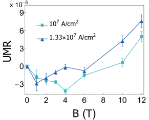
S5 Model Hamiltonian and spin canting
We consider the interfacial layer of the FeRh with broken inversion-symmetry as a two-dimensional antiferromagnetic square lattice with Rashba spin-orbit interaction, which can be described by the following tight-binding Hamiltonian [48, 2]
| (S.1) |
where is the on-site energy, is the s-d exchange constant between the local moments and the electron, is the Rashba spin-orbit coupling constant, and and are Pauli matrices which signify the sublattice and spin degrees of freedom, respectively. The nearest-neighbor hopping is represented by , where is the hopping term and the lattice constant.
In the semiclassical Boltzmann transport formalism, the nonlinear charge current density of the -th band is , where is the component of the electric field, and is the group velocity of the -th band. Note that the electric field is related to the applied current as , where is the applied current, is the longitudinal resistivity of the bilayer and and are the width and thickness of the bilayer, respectively. To find the nonlinear conductivity associated with the UMR, , we integrate by parts and sum over the conduction bands to find
| (S.2) |
where is a Lorentzian distribution centered at the Fermi energy . Without loss of generality, we assume and .
The Hamiltonian, Eq. (S.1), is modified by spin canting when an external magnetic field is applied perpendicular to the Néel vector. More specifically, the sublattice magnetizations tilt towards the applied field by an angle relative to the Néel vector, resulting in a net magnetization along the field direction. To calculate the canting angle , we consider the magnetic energy density of FeRh in the antiferromagnetic phase
| (S.3) |
Here, and are the magnetizations of sublattices A and B, is the effective exchange field measuring the interaction between the two sublattices and is the saturation magnetization, where we take . Initially, let and . After canting, and . Thus, . Minimizing the magnetic energy with respect to , we obtain the canting angle as .
To incorporate the spin canting into Eq. (S.1), we note that components of the two sublattice magnetizations that are parallel to now couple with the same sign to the electronic spin. Therefore, to go from the initial configuration to the new equilibrium, we must make the substitution in the Hamiltonian, which enables us to calculate the UMR with canting. To do so, we use the following parameters: Å, s, , eV, , [48], [48, 49], [48, 50], T (corresponding to at T) and width of spectral function .
[] \sidesubfloat[]
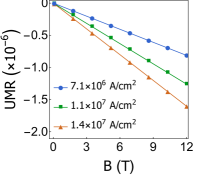
\sidesubfloat[]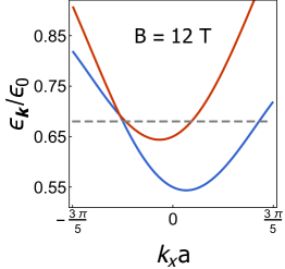 \sidesubfloat[]
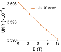
We note that the choice of T, used to match theory with the experimental results, corresponds to a magnetic susceptibility that is approximately five times larger than what has been measured for bulk, powder FeRh, in the antiferromagnetic phase [65]. We are unable to measure the magnetic susceptibility of our samples directly due to a strong diamagnetic background signal from the MgO substrate, which overwhelms any signal that would arise from the antiferromagnetic thin film. We attribute the increased susceptibility that our analysis suggests (compared with bulk samples) to the residual ferromagnetism in the FeRh thin-film, near the MgO interface. This residual ferromagntism provides an additional exchange field that aligns with the external field, effectively increasing the canting angle.
S6 Absence of UMR sign change in nonmagnetic and ferromagnetic systems
To calculate the UMR in the ferromagnetic and nonmagnetic phases, we must first modify the Hamiltonian accordingly by noting that it no longer has a sublattice degree of freedom. The nonmagnetic phase is obtained in the limit . In this limit, the canting term vanishes. Thus, in the absence of a strong effective Zeeman term, as displayed in Fig. S.6, there is little deformation in the band structure even up to fields as strong as 12 T, which implies a weaker UMR in the nonmagnetic phase. Furthermore, since the Hamiltonian is linear in the magnetic field, the UMR predicted by the model will also be linear. This behavior is shown in Fig. S.6.
In ferromagnetic systems, it is known that the magnitude of the UMR is maximized when the magnetization is aligned perpendicularly to the applied current. In this geometry, the effective exchange field, , always has dominant contribution to the band distortion (as plotted in Fig. S.6) as well as the resulting Rashba UMR so that increasing the external magnetic field (say, up to 12 T) can only change the magnitude of the UMR by a negligibly small amount (as displayed in Fig. S.6), let along cause a sign change.
S7 Comparison with USMR
In order to estimate the contribution of the unidirectional spin Hall magnetoresistance (USMR) to the nonlinear response, we use the relation [27]
| (S.4) |
where and are the spin asymmetries in the density of states at the Fermi level and in the conductivity, is the Drude conductivity, the spin diffusion length and the layer thickness. Here, the indices and refer to antiferromagnet (FeRh) and heavy metal (Pt), respectively. The spin asymmetry in the system may be approximated by the ratio of the magnetic energy associated with (which dominates the Zeeman coupling) and the Fermi energy, as . After substitution, using the material parameters for the FeRhPt sample, we find that USMR/UMR , which implies that the USMR may be safely neglected in the present study.
[] \sidesubfloat[]
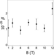
S8 Extraction of linear UMR contribution in the data
In order to better compare the experiment with the theory, which assumes a UMR linear in the applied current, the linear UMR contribution in the experiment was extracted by fitting to each applied magnetic field in Fig. 3a (Fig. S.7).
No sign change or consistent field dependence is observed for the cubic UMR contribution and the cubic coefficient is mostly centered around the fixed value (Fig. S.7). Unlike the higher order UMR, the linear UMR contribution demonstrates a clear field dependence and the sign change for all current densities occurs at T, close to what is predicted in the theory (Fig. 3c).
S9 Analytical approximation of sign-reversal field
In order to gain a better understanding of the sign reversal field value and its dependence on the system parameters, it is convenient to express it in an approximate analytical form. To this end, consider the following field expansion of the UMR
| (S.5) |
where
| (S.6a) | |||
| (S.6b) | |||
Here, we have introduced the dimensionless Rashba SOC constant , s-d exchange constant , Fermi energy , spectral width and hopping parameter . While the functions and scale linearly with the electric field, they turn out to have rather complicated dependences on the materials parameters.
Solving for the crossing point magnetic field, , we find that
| (S.7) |
This expression allows us to make a rough estimation of the sign reversal field value once the parameters of the system are known. Using typical values of the materials parameters from the literature, which were also used in the numerical calculation in the main text, namely [48, 50], [48, 49], [48], and T, we find that T, which agrees well with both the observed value ( T) and the numerical calculation of the UMR ( T).
As a final note, it is worth mentioning that, despite its complicated form, Eq. (S.7) predicts that the sign reversal field will scale linearly with the antiferromagnetic exchange field , which may be useful in future studies of UMR in antiferromagnetic systems.
S10 Epitaxial growth of FeRh on MgO
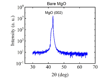
Because our study is based on the thin film of FeRh, it is crucial to characterize the structural property of thin FeRh film on the MgO substrate. In Figs. S.8 and S.8, X-ray diffraction (XRD) measurements are shown for both a [001]-oriented MgO substrate and the MgO substrate with a FeRh films deposited upon the surface. A Bragg peak corresponding to the (002) family of lattice planes in MgO is present for both measurements. In Fig. S.8, there are two additional peaks corresponding to the (001) and (002) family of planes due to the FeRh film. The peak positions correspond to lattice constants along the c-axis of 0.421 nm and 0.300 nm for MgO and FeRh respectively. These correspond to a lattice mismatch of approximately 0.3%, which is relatively small considering that the [100] orientation of FeRh tends to grow along the [110] direction of the MgO substrate [66]. These parameters are consistent with other reports in the literature [67, 68, 69], and are consistent with the epitaxial growth of FeRh on the MgO.
[] \sidesubfloat[]
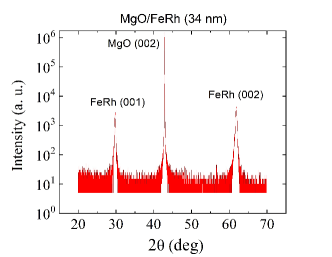
Due to the epitaxial strain from the MgO substrate, we observe in Fig. S.9 that the temperature window of hysteresis widens and transition temperature lowers when we have a thinner FeRh film. Because the phase transition in FeRh highly depends on the lattice structure, the strain from the MgO leads to the competition between the ferromagnetic and antiferromagnetic domains, and thus widening the temperature window of hysteresis and also pushing the transition temperature to a lower value.